Week 1 Challenge
Answer of the question 1.1
1) Answer
Aim: Aim to this question is we have to familiar with the software. and important to know the basics of Staad.pro.
Introduction: Staad pro stand for Structural Analysis and design Program. it include the GUI Graphic interface for Visualization And Contains Various Design codes.
Procedure:
Steps:
- First We need to open the Staad Pro Software.
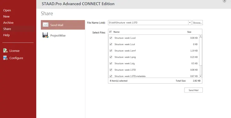
- Now Click to the Share Icon
- Click to the Send Mail
- Browse the file we want to Share
- Click on send mail.
- Now We ensure We are singing
2)Answer:
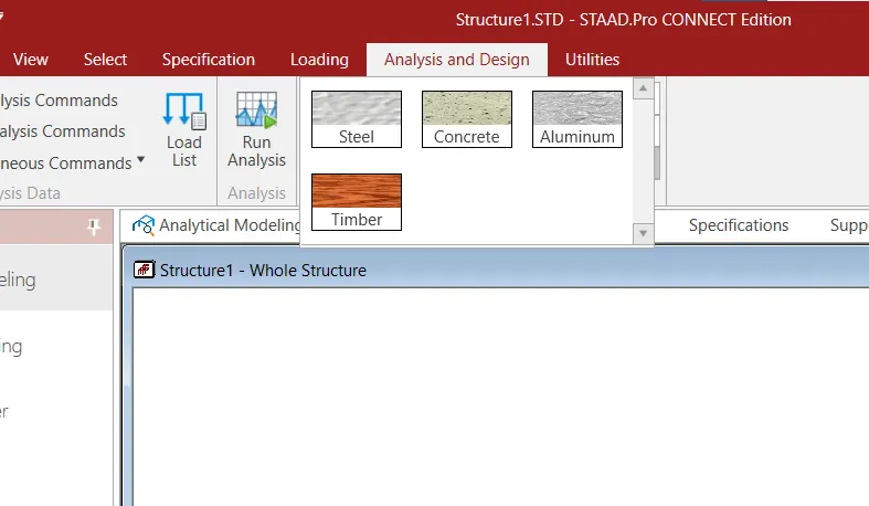
the Type Of material use in used in staad pro is Following
- Steel
- Concrete
- Aluminum
- Timber
3) Answer:
- If we want to capture picture in external file. go to the menu option
- Go to edit
- Copy picture
- Open the application
- Now paste it i
- it is directly saved
4) Answer:
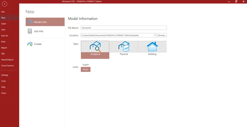
in the staad pro we can create modal through the following three ways
- Analytical modal
- physical Modal
- Building modal.
5)
- In STAAD.ProgramProrgram Physical Modeler, the general order of operations is that we first select physical objects and then assign properties or perform some operation on the selection.
- This differs from STAAD.Program, where there are many tasks in which you select the operation, property, or specification first and then assign that to some list of model objects.
Result: i completely write all the answers of the given qiestions.
Answer of the question 2.1
Aim: we have to discussed about design paramerts in this question.
Introduction: Staad pro stand for Structural Analysis and design Program. it include the GUI Graphic interface for Visualization And Contains Various Design codes.
Procedure:
1) Answer: Six Design paramer:
EUDL : EUDL stand for equivalent u.d.l on span of the beam . tis load value must be the unfactor load on span, During design the load value is multiplied by factor 1.2.
ELY : Ratio of effective length to actual length of column about minor axis.
ELZ: Ratio of effective length to actual length of column about major axis.
EUDL None : Equivalent u.d.l on span of the beam. This load value must be the unfactored load on span. During design the load value is multiplied by a factor 1.2. If no u.d.l is defined factored shear force due to gravity load on span will be taken as zero.
FYMAIN: Yield Stress 415N/mm^2 for main reinforcing steel.
FYSEC: Yield Stress 415 N/mm^2 for secondary reinforcing steel.
2)Answer: Different types of Cursor available in STAAD PRO.
- Nodes Cursor : Used to graphically select nodes.
- Beam Cursor: Used to graphically select nodes.
- Plate Cursor: Used to graphically select nodes.
- Solid Cursor: Used to graphically select nodes, members and elements of the structure simultaneously.
- Geometry Cursor: To select nodes, members, or elements using the Geometry Cursor, simply click on the desired structural components.
- Memebrs Cursors:Members may be user defined or may be generated automatically using the Auto Form Member tool.
- Plates & Solids Cursor: Used to add comments and titles to pictures and result diagrams. The added text can be plotted, too.
- Select test: Selects the last objects selected if they have been deselected or if the selection set has changed
- Previous: Selects the last objects selected if they have been deselected or if the selection set has changed.
- Load:Used to modify any load already applied on the model by double-clicking it.
3)Answer:
We used this for navigate the modal.
- Click the Rotation Gizmo to display preset views. Click the invert icon to display the reverse of these views.
- Click and drag on the Rotation Gizmo axes to rotate the view about that global axis.
- Click on the zoom controls to zoom in or out of parts of the model.
- Click on the Perspective control to display the perspective switch and slider.
4)Answer: Go to the support command in the tool command
- Click to the create support command
- There we can get options like fixed support, pin support, Fixed but
- Enforced but support
- Cable support
- Inclined support
5) Answer:
- DBR stand for Design basis report
- To take up a project from the scratch to the end this is need.
- To specify and compile the data required for analysis and design of structural element of the project.
- I clearly depict the assumptions and specifications that are being used to develop the construction document for a project.
- it will help to avoid the scope and the creep that can derail the project schedule and lead to budget overtness'
- it contains the general Column drawing
Result: i completely write all the answers of the given qiestions.
Answer of the question 3.1
Aim: We have to write name of the structure system in staad Pro.
Introduction: Staad pro stand for Structural Analysis and design Program. it include the GUI Graphic interface for Visualization And Contains Various Design codes.
Procedure:
1)Answer: They are four structural system in staad pro.
| Structure System | Geometry | Loading | Deform | Joint |
| Space | 3D | 3D | 3D | ANY |
| Plane | 2D | 2D | 2D | ANY |
| Frame | 2D | PARPEN TO XZ | PERPEN TO XZ | ANY |
| Truss | 3D | 3D | 3D | Pinned |
2)Answer: They are two coordinate system in Staad pro.
- Global Axis: Global Axis is Fixed in the coordinate system.
- Local axis: local axis is variable
- This is used for the orientation of the beam with the load variable.
3)Answer:
- DBR stand for Design basis report
- To take up a project from the scrach to the end this is need..
- To specify and compile the data required for analysis and design of structural element of the project.
- I clearly depicts the assumptions and specifications that are being used to develop the construction document for a project.
- it will help to avoid the scope and the creep that can derail the project schedule and lead to budget overtness'
- it contains the general Column drawing
4)Answer:
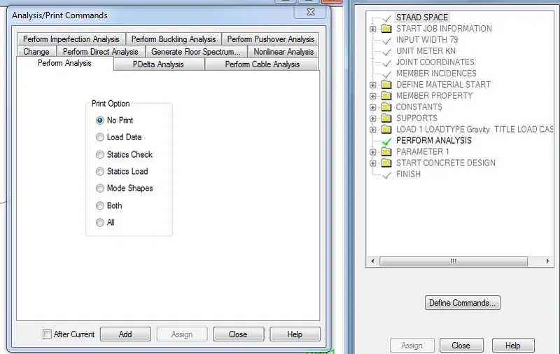
We have difference types of analysis
5)Answer:
Fixed Condition: in this condition, the node or the end condition are fixed are restrained with the 'FX' , 'FY' 'FZ' and the moment are also restrained
Fixed But: in this condition the node are 'Fx' and 'MZ' are released as it is horizontal rolled support
Result: i completely write all the answers of the given questions.
Answer of the question
-:PRACTICAL:-
Aim: in this question wee have to practical some commands and create project with following lines
Create a STAAD Model with the following Specification
a. A beam of span 16m
b. Support : Fixed on one end and Roller support(Horizontal) on the other end
c. A point load of 50 kN at the mid-point
d. Draw SFD and BMD using software
Procedure:
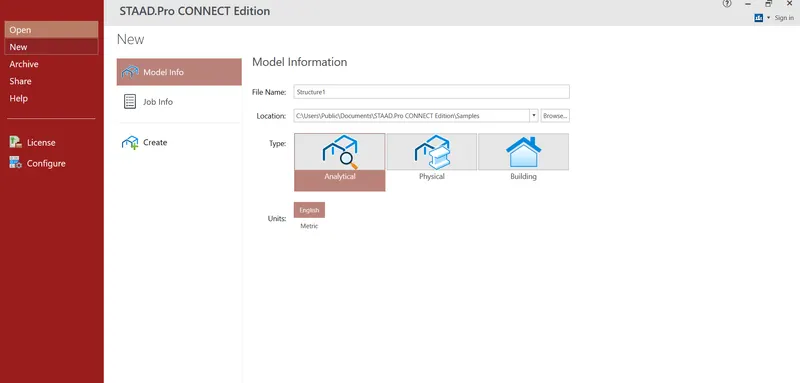
Step-1
- Open the Staad Pro Software and Create an Analytical modal with metric unit.
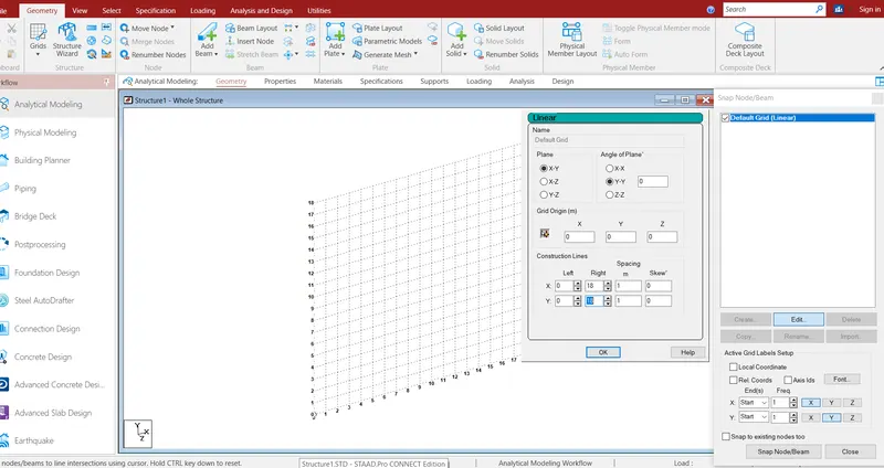
Step-2
- Grid Dimension spacing -1m
- Go to grid to beam
- put span more than 16
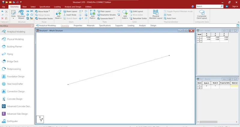
Step-3
- Click on the Grid menu and Draw a beam of span 16 m
- For the node View click on CTRL +N or Right click and labels and view nodes
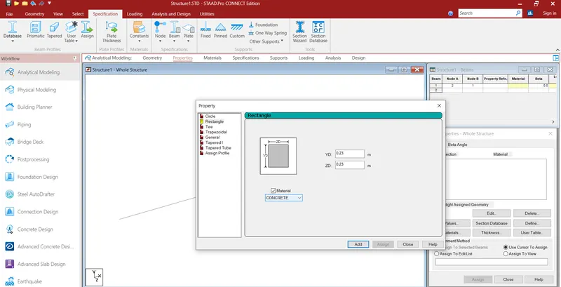
Step-4
- Go to property
- Click to the define and go to reactangle
- define the size 230mm by 230mm
Step-5
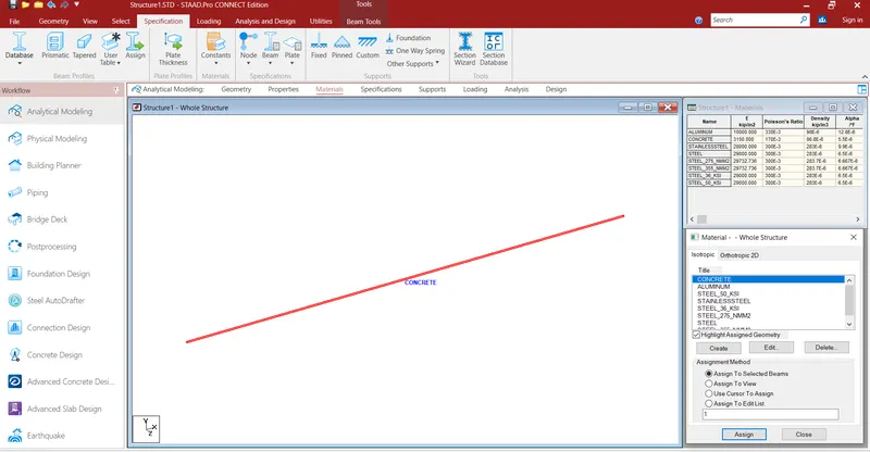
- Assign the concrete material to the beam
Step-6
b)
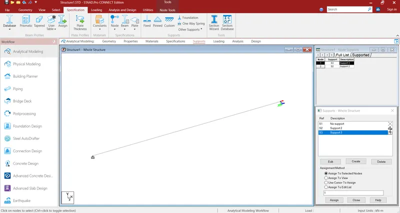
- Now go to Support
- Click to create support
- Choose support
- Adding Fixed support and Roller support Horizontal on other end
Fixed on one end and Roller support(Horizontal) on the other end
Step-7
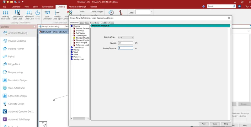
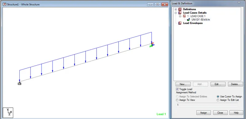
C. A point load of 50 kN at the mid-point
- Click to the loading
- Create the load
- click to the member weight
- weight 50 kN
- Distaance 8 m
Step-8
- Now run the analysis
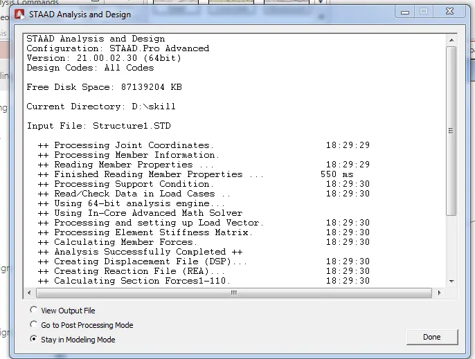
Step-9
- SFD and BMD using software
- Now we can see the bending moment
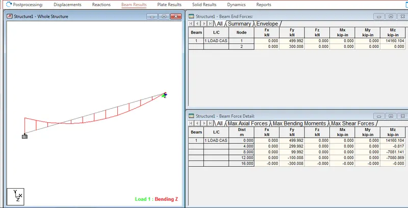
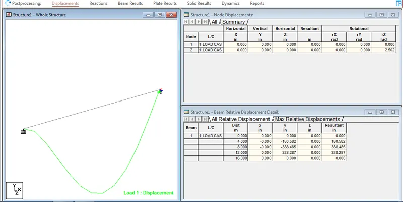
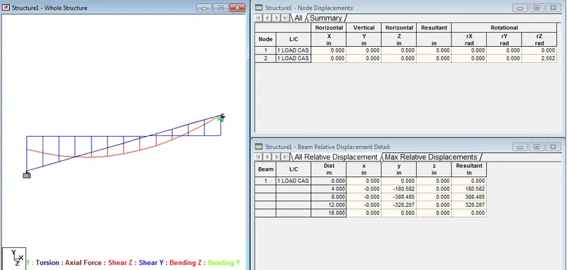
Result : i completely practice all the questions and give the result by the screenshot.