Week 1 Challenge
1. 1. Write the steps involved to upload a .std file through web mail?
2. Name the different materials that can be designed using STAAD Pro.
3. Is it possible to capture images in STAAD Pro? If yes how?
4. Name the three ways by which you can create a model.
5. Write the steps followed to assign properties in a model.
ANS:
1.1. Write the steps involved to upload a .std file through web mail?
Procedure:
- Open the software Staad pro in the landing page
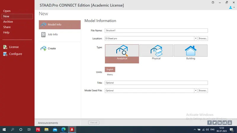
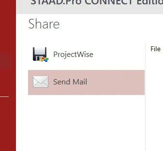
- Click on share icon in

- Click on send mail
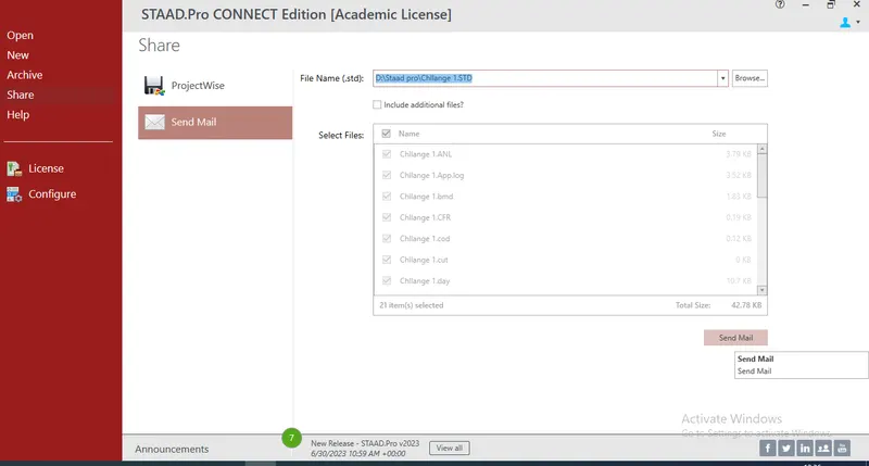
- Browse the file u want to share
- click on send mail
- Ensure that you are sign in
RESULT: Send a .s td file through mail
1.2. Name the different materials that can be designed using STAAD Pro.
Procedure:
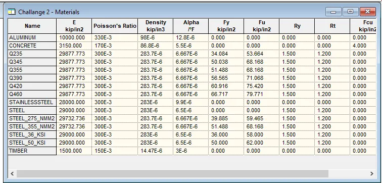
- There are four main types of material which can be designed using staad.pro
- These are Steel, concrete, aluminium and timber.
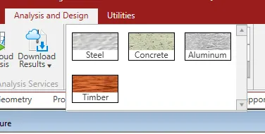
- There are also differnet materials are available and you can crea by using create option in material stage
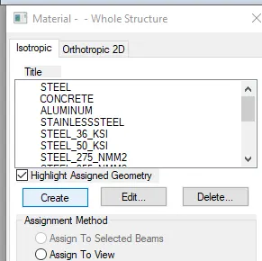
RESULT: Listing the material in saad pro
1.3. Is it possible to capture images in STAAD Pro? If yes how?
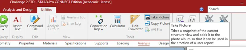
- Yes it is possible to capture images in Staad pro
Procedure:
- Go to Utilities
- Select take picture
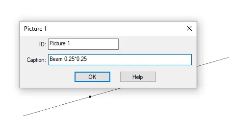
- Provide Caption and ID - click on ok
- If you want to get the pictures in an external file ( like a word file, excel file, MsPaint etc.) go to the menu option Edit > Copy Picture, open the application you want and do a paste in there. Files saved through Take Picture option are not directly saved in common picture formats like bmp, jpg, png.

RESULT: Describe the procedure of take a picture
1.4. Name the three ways by which you can create a model.
Procedure:
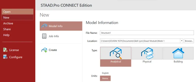
- Click on staad pro then the display the
- Basically we can create a model by Analytical, Physical and Building.
RESULT:
1.5. Write the steps followed to assign properties in a model.
Procedure:
- Open staad pro. then provide regarding information
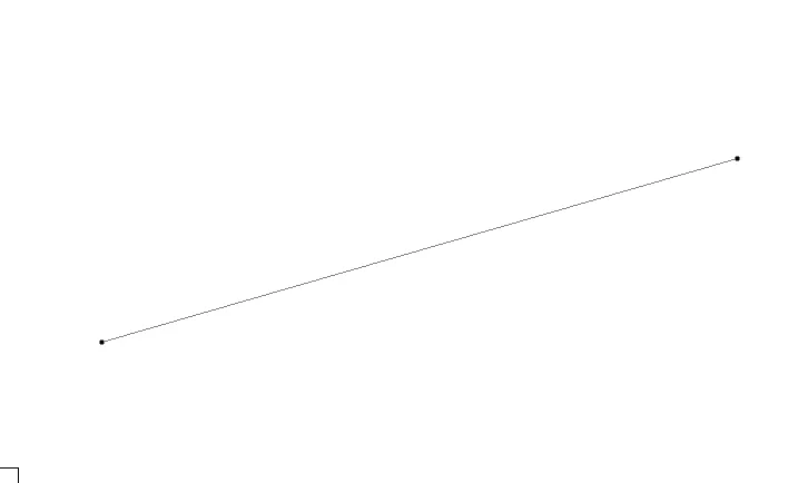
- Draw the beam in Geometry stage
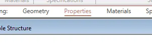
- Then go to property stage
- Click on define
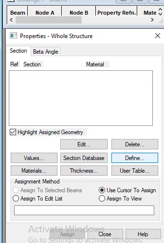
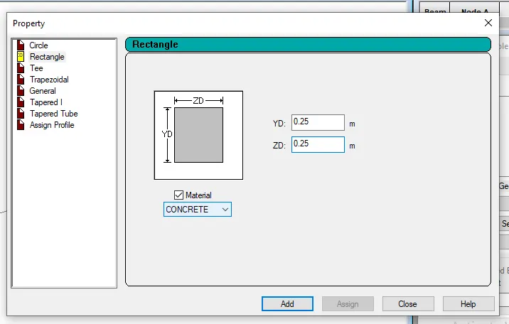
- Select Rectangle porvide its depth and breadth And material - Add it and then closed tab
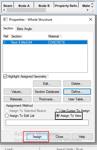
- Select section - choose asign to view - assign - yes
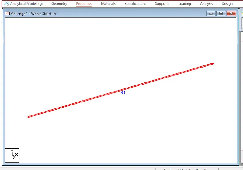
RESULT: Assign the property to model
2. 1. Name any six design parameter involved in RCC design.
2. What are the different cursor types available in STAAD Pro?.
3. How will you generate different views for a model? State the steps involved.
4. Explain the procedure to define a “Simply Supported” condition in STAAD Pro
5. Name any five topics that you will include while creating DBR.
6. Describe the term “Multi material design” of STAAD Pro.
ANS:
2.1. Name any six design parameter involved in RCC design.
ANS:
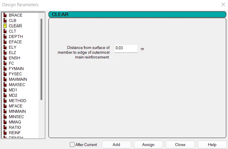
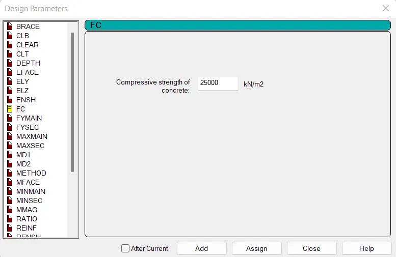
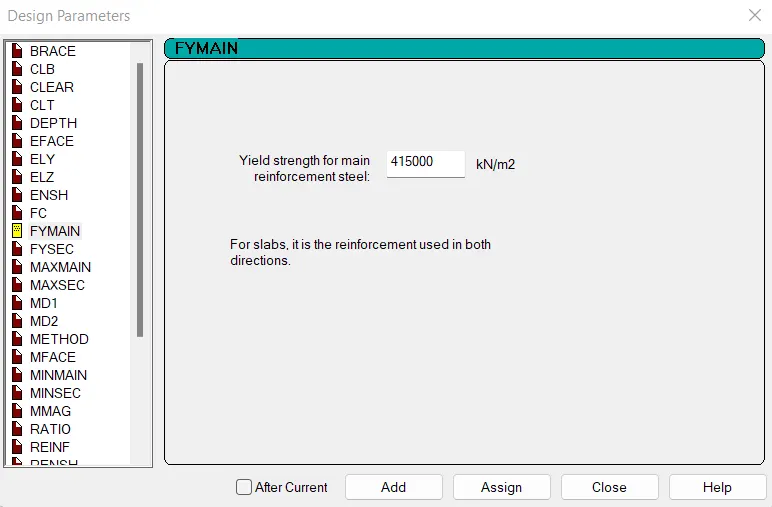
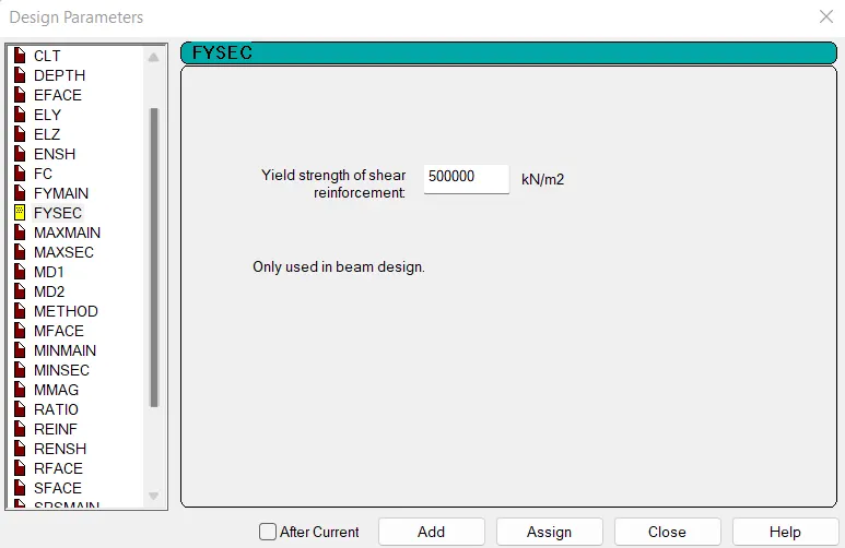
For that Go to the design stage and click on define parameter we get parameter list for steel memebers and rcc members i am explaining below six parameters out of them
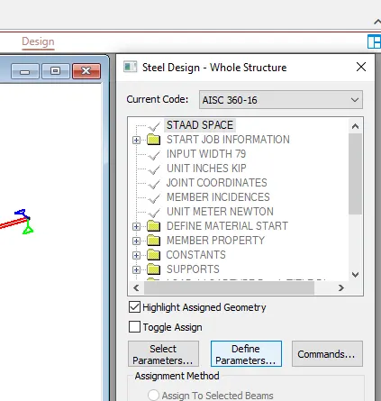
Name of six design parameter included in reinforced cement concrete design are-
1. Clear cover:
2. Characteristic compressive strength of concrete
3. Yield Strength of main rebar.
4. Yield strength of secondary rebar
5. Maximum main rebar dia
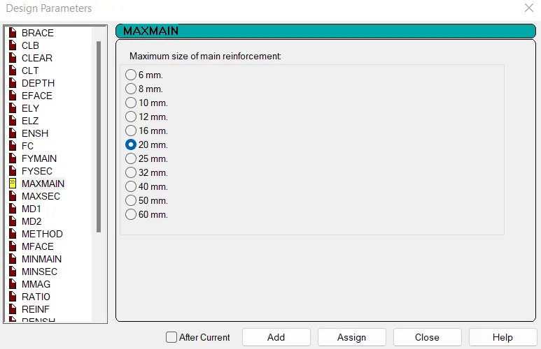
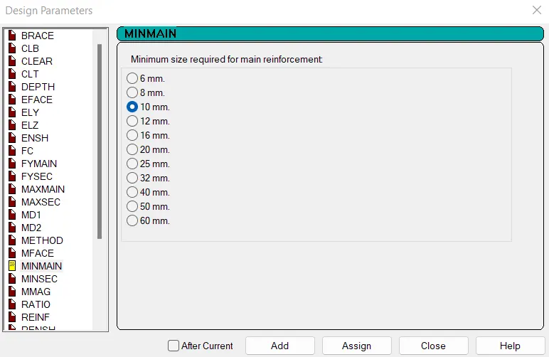
6. Minimum main rebar dia.
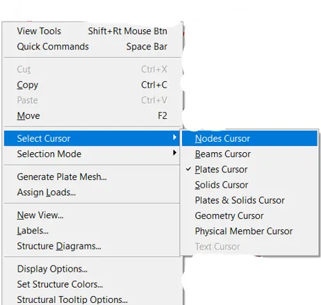
2.2. What are the different cursor types available in STAAD Pro?
ANS:
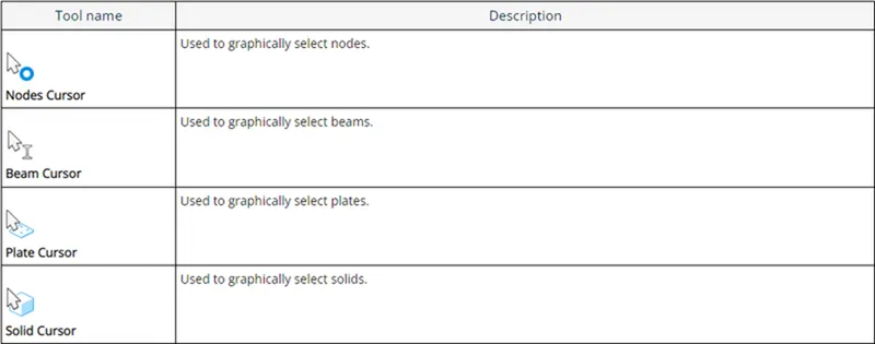
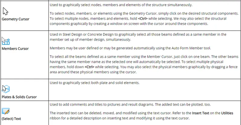
- There are basically seven types of cursor available in Staad Pro
1) Nodes Cursor.
2)Beams Cursor.
3)Plate Cursor.
4)Solids Cursor.
5)Geometry Cursor.
6)Physical member Cursor.
7)Text Cursor.
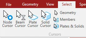
- In Staad pro to select these cursor there are two ways
A) Right click - select cursor - and choose cursor type
B) Go to select tab - select cursor which you required from cursor section
2.3. How will you generate different views for a model? State the steps involved.
ANS:
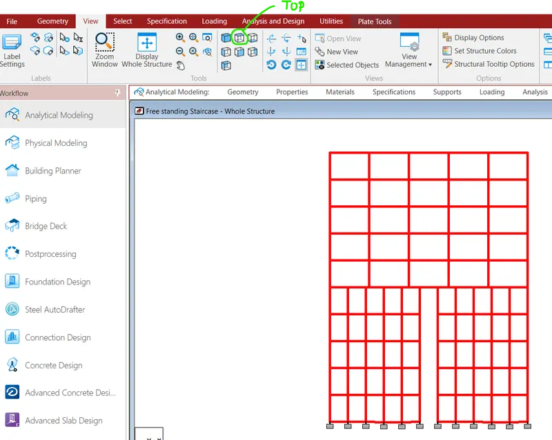
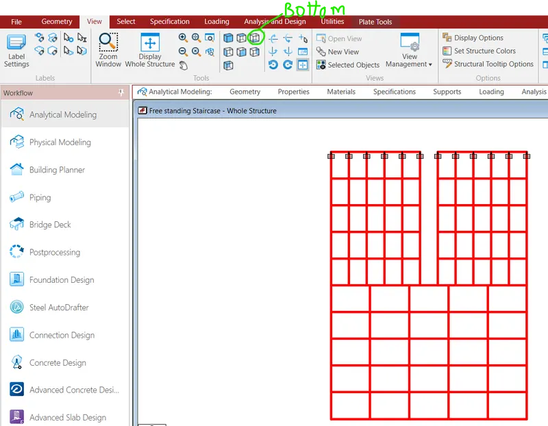
- There are 7 views i.e. 3D, Top, Bottom, Left, Right, Front, and Back
- Go to view tab and then click to different views from that tab -
* Click on 3d view

* Click on Top view
* Click on Bottom view
2.4. Explain the procedure to define a “Simply Supported” condition in STAAD Pro
ANS:
- Open staad pro. then provide regarding information
- Draw the beam in Geometry stage
- Go to support tab in staad.pro file
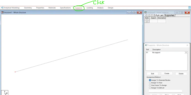
- Then click to crete icon and go to pinned support condition and click add.
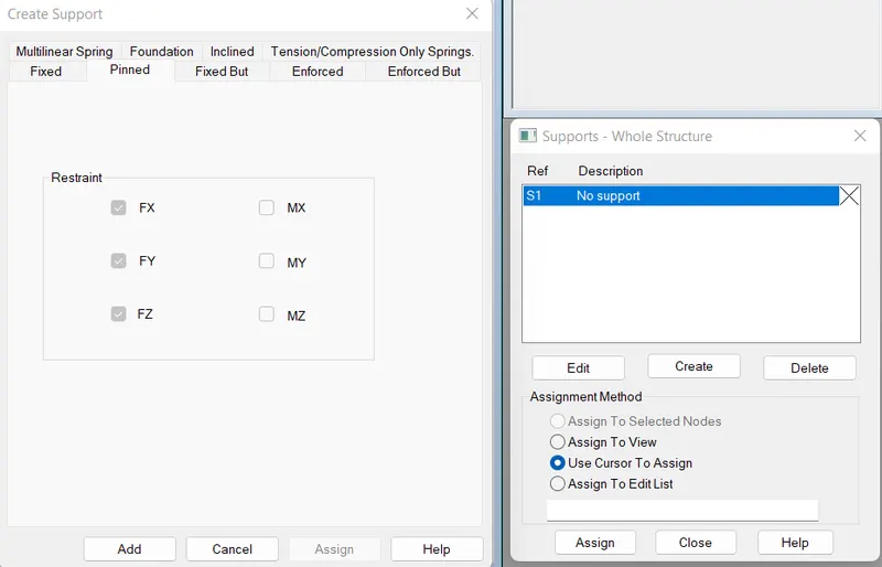
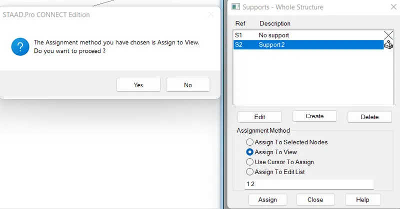
- Then click assign to view and click to yes
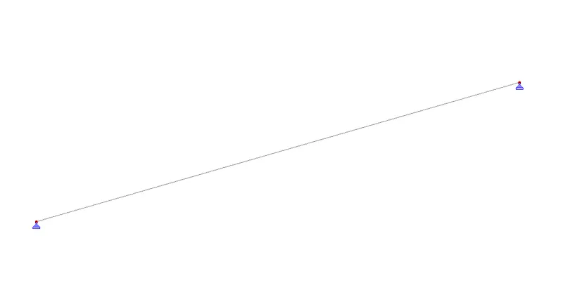
- Final result of simply supported beam
2.5. Name any five topics that you will include while creating DBR.
ANS:
Here are the five topics which should be include in the Design basis report-
1) Introduction - Which covers scope and structure of this note
2) Structural Layout- It covers brief description about structural framing system adopted for project showing plan and section of building
3) Loads and Loads Combination- It covers brief description about loads and loads combination considered in design
4) Analysis and Design methodology- It describes the approach for structural analysis and design
5) Quality Annexure plan- It covers the quality control aspects followed in design and preparation of drawings.
2.6. Describe the term “Multi material design” of STAAD Pro.
ANS:
i) After Analysis structure has to be designed to carry loads acting on it considering a certain Factor of safety
ii) In India structures are designed by using various Indian codes for both concrete and steel structure.
iii) The design in staad pro supports over 70 international codes and over 20U.S codes in 7 languages
iv) After designing the structure it is again analyzed and results of analysis for each beam and column is shown in output file.
3. 1. Name the structure systems in STAAD Pro? Explain each system?
2. Explain the coordinate system adopted in STAAD Pro software.
3. Elaborate DBR and its uses.
4. Explain the different types of analysis options in STAAD pro.
5. Explain the difference between Fixed and Fixed But condition.
3.1. Name the structure systems in STAAD Pro? Explain each system?
ANS:
A STRUCTURE can be defined as an assemblage of elements. STAAD.Pro is capable of analyzing and designing structures consisting of frame, plate/shell, and solid elements. Almost any type of structure can be analyzed by STAAD.Pro.
- a) SPACE
- A3D framed structure with loads applied in any plane. This structure type is the most general.
- b) PLANE
- This structure type is bound by a global X-Y coordinate system with loads in the same plane.
- c) TRUSS
- This structure type consists of truss members which can have only axial member forces and no bending in the members.
- d) FLOOR
- A 2D or 3D structure having no horizontal (global X or Z) movement of the structure [FX, FZ, and MY are restrained at every joint]. The floor framing (in global X-Z plane) of a building is an ideal example of a this type of structure. Columns can also be modeled with the floor in a FLOOR structure as long as the structure has no horizontal loading. If there is any horizontal load, it must be analyzed as a SPACE structure.
Specification of the correct structure type reduces the number of equations to be solved during the analysis. This results in a faster and more economic solution for the user. The degrees of freedom associated with frame elements of different types of structures is illustrated in the following figure.

3.2. Explain the coordinate system adopted in STAAD Pro software.
ANS:
STAAD.Pro uses two types of coordinate systems to define the structure geometry and loading patterns.
A) globle coordinate system
B) Local coordinate system.
A) globle coordinate system:
- The globle coordinate system is an arbitrary coordinate system in space which is utilized to specify the overall geometry & loading pattern of the structure.
- If you changing "Beta angle" in material section but use global axis loading is not chnaging i.e. Orientation is not changing.
i) Conventional Cartesian (Rectangular) Coordinate System:
- This coordinate system is a rectangular coordinate system (X, Y, Z) which follows the orthogonal right hand rule. This coordinate system may be used to define the joint locations and loading directions.
ii) Cylindrical Coordinate System:
In this coordinate system, the X and Y coordinates of the conventional Cartesian system are replaced by R (radius) and Ø (angle in degrees). The Z coordinate is identical to the Z coordinate of the Cartesian system and its positive direction is determined by the right hand rule.
iii) Reverse Cylindrical Coordinate System:
This is a cylindrical type coordinate system where the R- Ø plane corresponds to the X-Z plane of the Cartesian system. The right hand rule is followed to determine the positive direction of the Y axis.
* They are four structural system in staad pro
| Structure System | Geometry | Loading | Deform | Joint |
| Space | 3D | 3D | 3D | ANY |
| Plane | 2D | 2D | 2D | ANY |
| Frame | 2D | PARPEN TO XZ | PERPEN TO XZ | ANY |
| Truss | 3D | 3D | 3D | Pinned |
3.3. Elaborate DBR and its uses.
Ans
There are following points to be consider And its uses:
i) DBR is nothing but Design Basis Report.
ii) To specify and compile data required for analysis and design of structural elements regarding the project.
iii) It clearly depicts the assumptions and specification that are being used to develop the construction documents for a project.
iv) It will also avoid the scop creep that can derail the project schedule and lead to budget overruns.
v) It basically transform the WHAT into HOW.
vi) When a particular employee joins the new company in midway of project this DBR will help him in understanding the project current situation.
vii) All the specification and poperties, material etc all the information is akready mentioned in DBR.
viii) So he need not to go to highr authority everytime.
ix) DBR will help him in that situation.
3.4. Explain the different types of analysis options in STAAD pro.
ANS:
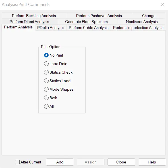
1) Perform Analysis -
i) This is a Linear static 1st Order differential analysis
ii) This type of analysis is used for Building of primary loads cases
iii) Perform analysis is used to design every single elements .
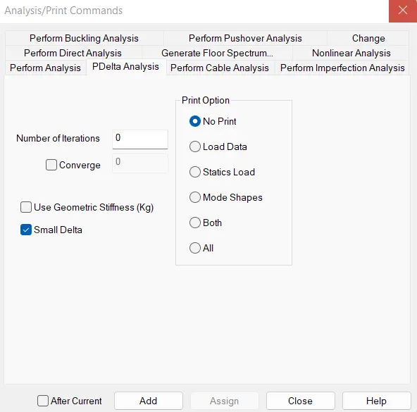
2) P - Delta Analysis -
i) This is 2nd Order analysis
ii) In which it governs secondary load cases such as Seismic Analysis
iii) As name suggests it calculate the moment with respect to apply load and calculate deformation under apply loads
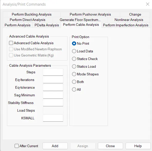
3) Perform Cable Analysis -
i) This analysis is used whenever we have cable element in our model
ii) Cable analysis is generally used for Crane loading or incase of Lifting Analysis
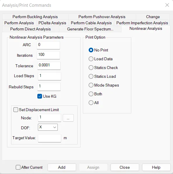
4) Non Liner Analysis -
i) This is an type of Static Non linera analysis
ii) This type of ananlysis is not applicable for Solid structures
iii) Non Linera Ananlysis does not considered plastic hing moment developed in structure .
5) Perform Pushover Analysis -
i) This type of analysis is used to study the seismic analysis
ii) Under this Analysis Deformation of structure is also studied .
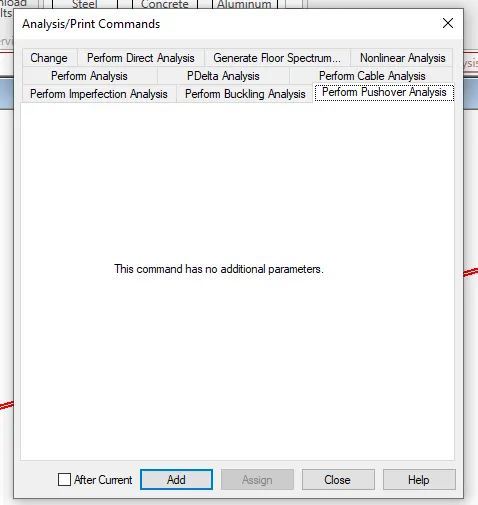
6) Perform Buckling Analysis -
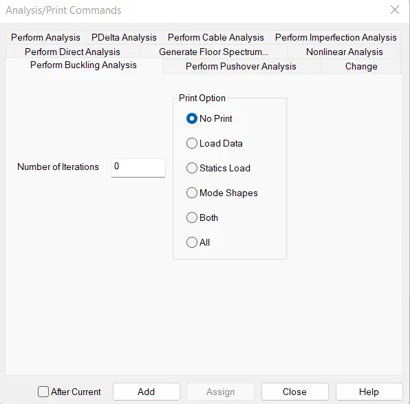
7) General floor spectrum Analysis -
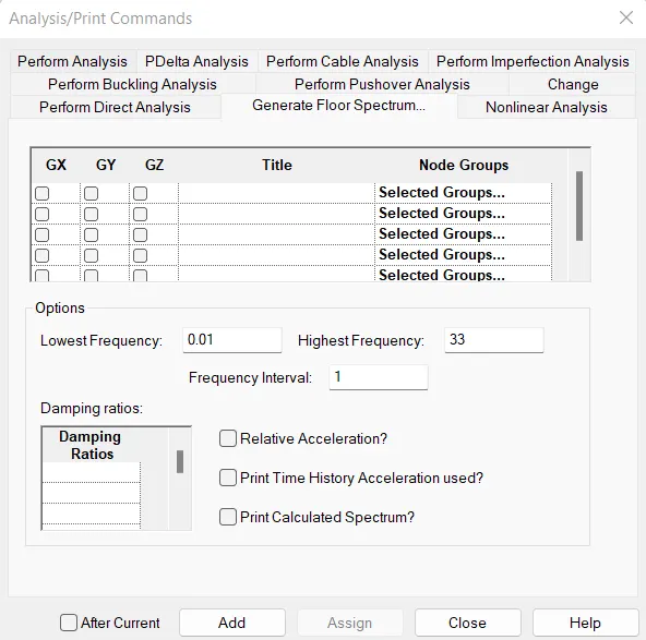
8) Perform direct Analysis -
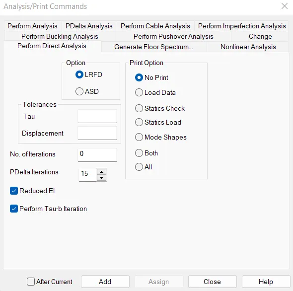
3.5. Explain the difference between Fixed and Fixed But condition.
ANS:
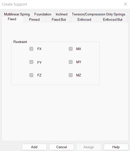
IN fixed condition the node or the end condition are fixed are restrained with the FX , FY, FZ and the moment are also restrained
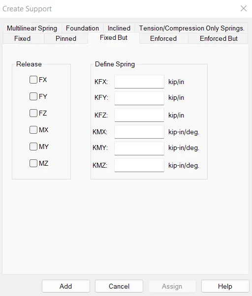
In Fixed But condition the node are Fx and MZ are released as it is horizontal rolled support
Practical
1. Create a STAAD Model with the following Specification
a. A beam of span 16m
b. Support : Fixed on one end and Roller support(Horizontal) on the other end
c. A point load of 50 kN at the mid-point
d. Draw SFD and BMD using software
AIM:
To Draw SFD and BMD for beam span 16m with point load 50kN at the mid point
TOOL AND COMMAND:
- Geometry
- Property
- Loading
- Supprots
- Analysis
- Design
- Run analysis
- Analysis command
- Command file
PROCEDURE:
Step 1: Open Staad pro:
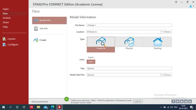
- First open the staad.pro software and fill all the project details and select unit system as Metric.
- Then select the model as analytical.
Step 2: To Draw Geometry:
- There are two methods to draw the geometry
1) By using nodes
2) By using grid
Here i am using node method
By using nodes
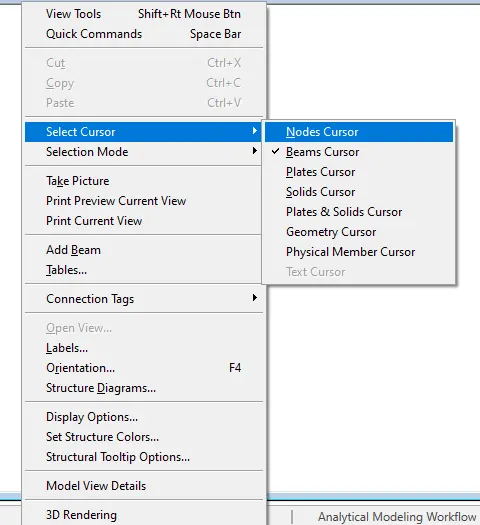
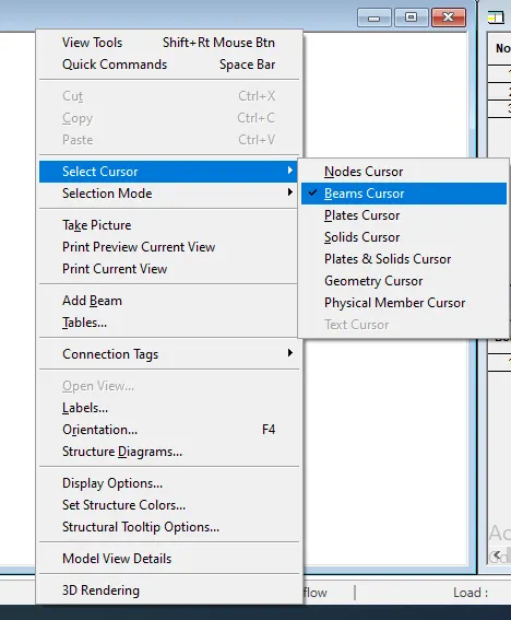
- Right click - select cursor - and choose nodes cursor
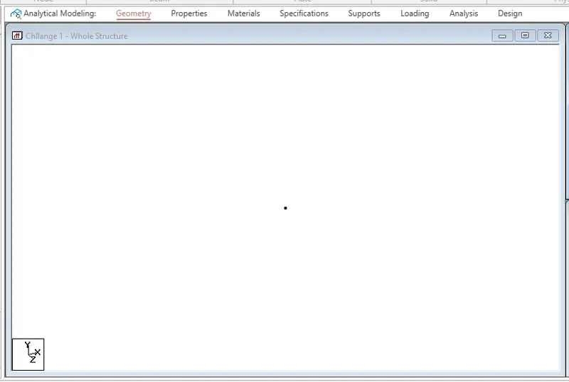
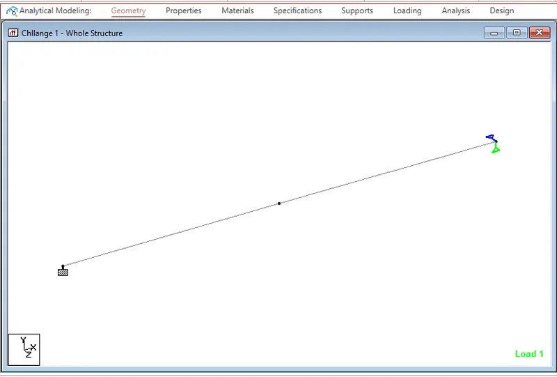
- Click on nodes tab in 1,X and put value (0,0,0)
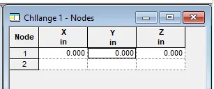
- We get origin node
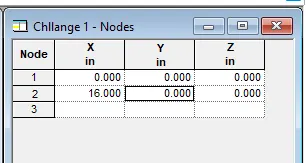
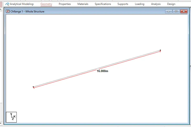
- Repeat this procedure for node 2 put value (16,0,0). We get 2nd node
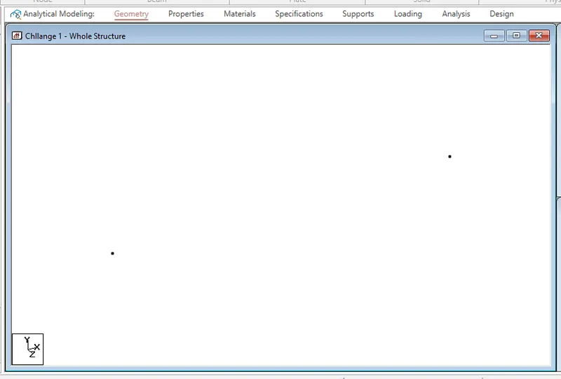
- For Draw beam- Right click - select cursor - and choose beam cursor
- Select add beam from geomerty tab
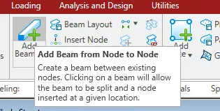
- Join these two nodes
- Then Change cursor type i.e. Node cursor - click on insert node
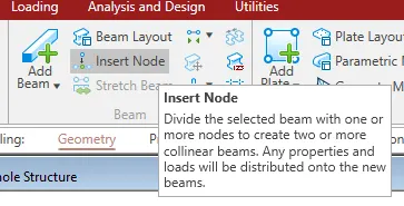
- Select "add mid point"
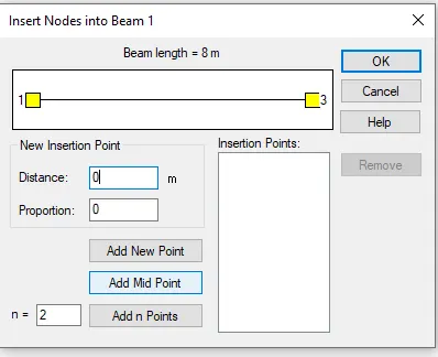
- The node is add at centre
Step 3: To Apply Properties:
- Click on properties tab which is 2nd stage
- Click on define
- Select rectangle and provide its depth and breadth my beam size is 250 x250
- Choose material as concrete b/c it is rcc beam - Add it by clicking on add - close tab
- Select section provide assignment method as "assign to view" - assign - yes
- Properties are assign to beam
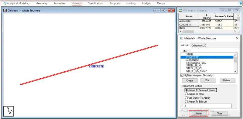
Step 4: To Apply material:
- Go to material tab - select concrete - Assign to view - assign - yes
- Material is assign to beam
Step 5: To provide Supprots:
- Go to next tab as a Supports Click on create
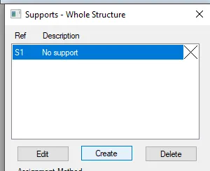
- create fixed support and roller support(It is Enforced but support where fx and all the moments are released) - Add - Close
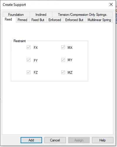
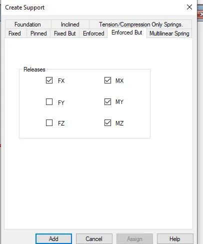
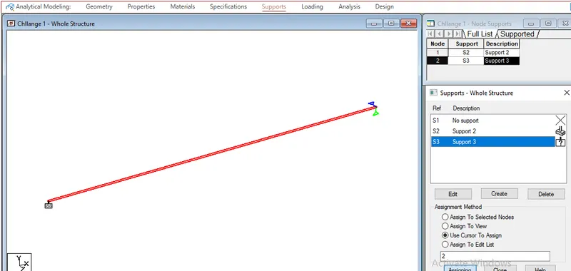
- Then assign them to the drawing by using "use cursor to assign" .
Step 6: To Apply Loading:
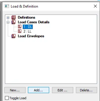
- Go to loading tab select "load cases deatils" - add
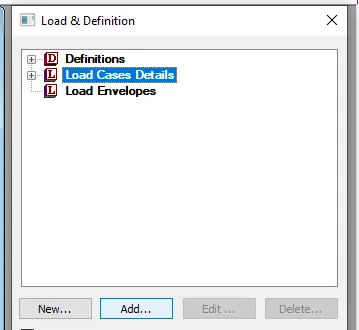
- Provide priamry load cases as DL And LL
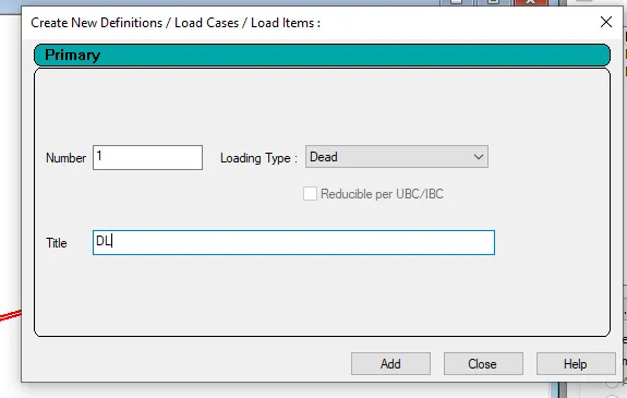
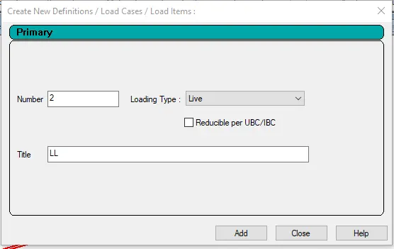
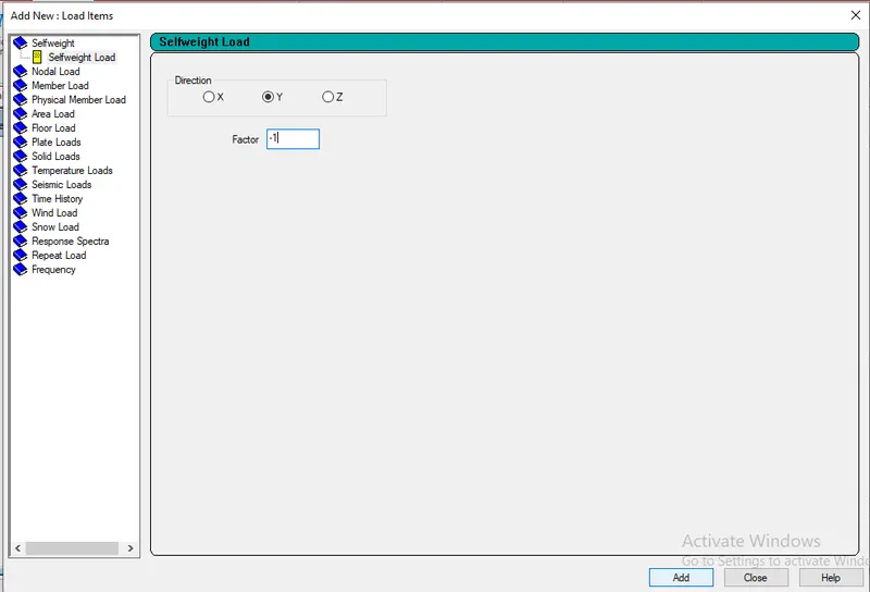
- Select DL And Click on add - provide self weight as -1KN - add
- Repeate this procedure for LL And put point load at mid node as -50kN
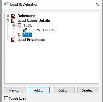
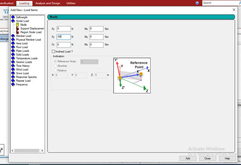
- Self weight is aasign to view and LL is use cursor to assign And both loads
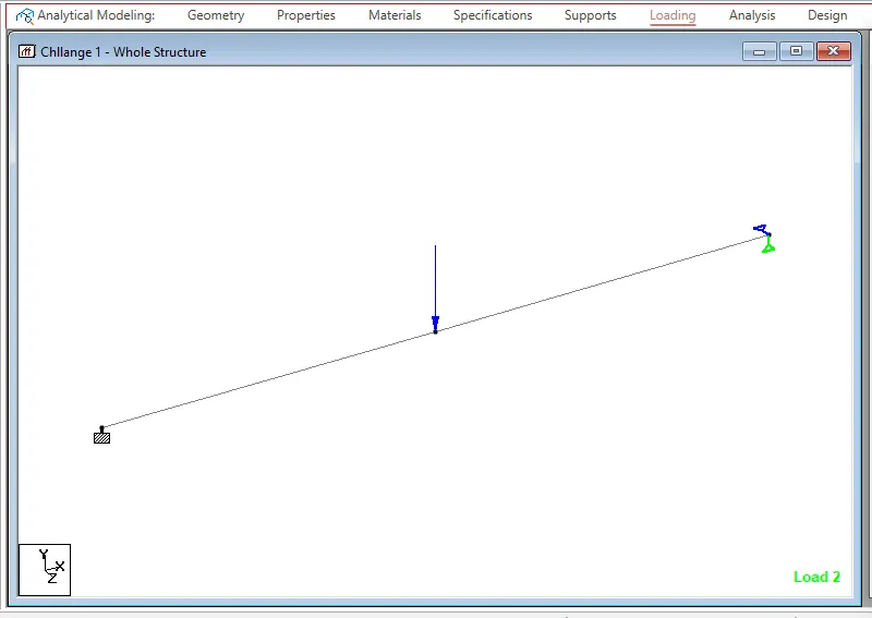
Step 7: Do Analysis:
- After going to analysis tab "Define command" - select perform analysis - add - close
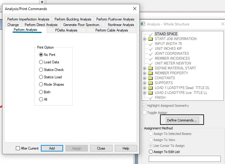
- From utilities tab click on Command file
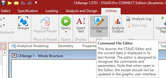
- Click on staad plane and change staad space name to staad plane close it and Save it
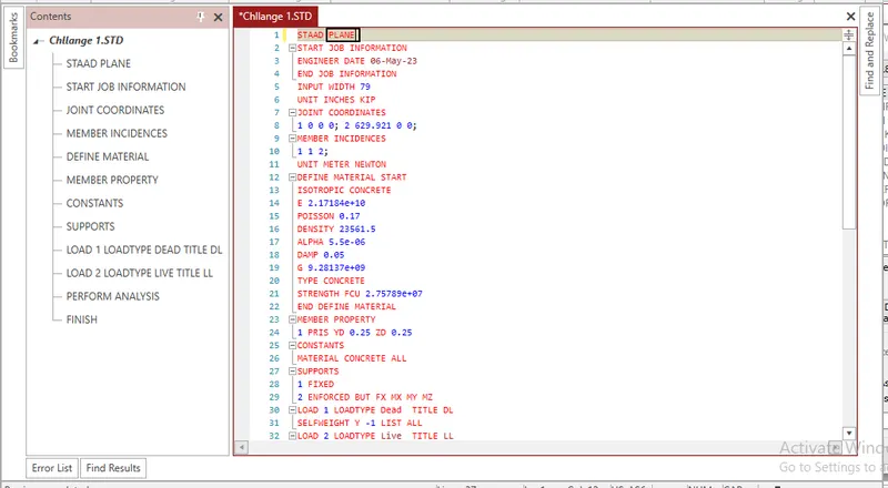
Step 8: Design by run analysis :
- Go to design Define parameters as Compressive strength of concrete and yeild strength of steel
- Select material type
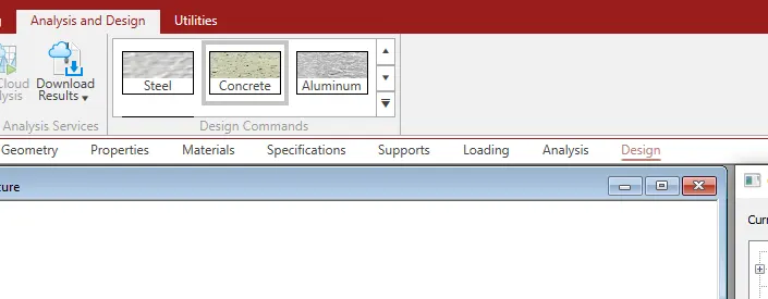
- Run analysis from analysis and design tab
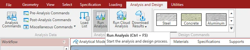
- Click on Go to post processing mode - Done
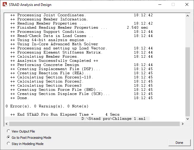
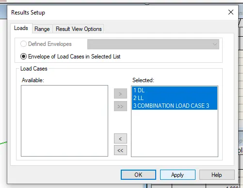
- Select loads - > - Apply - Ok
- We get a result
Step 9: SFD And BMD:
- Click on MZ we get BMD and click on FY we get sfd
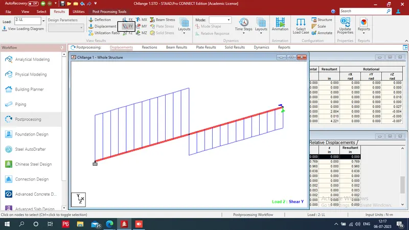
SFD
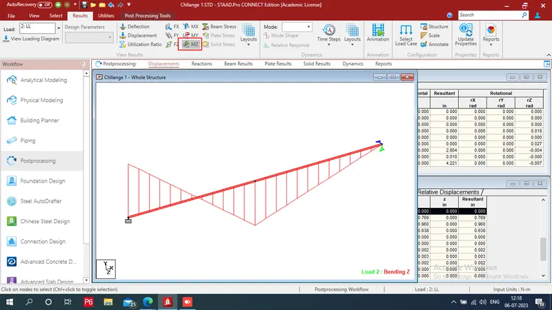
BMD
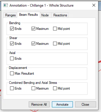
- From result tab choose annotate

- Check box as per requirement here i am choosing end and max for Bending and shear - Annotate - close
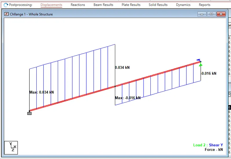
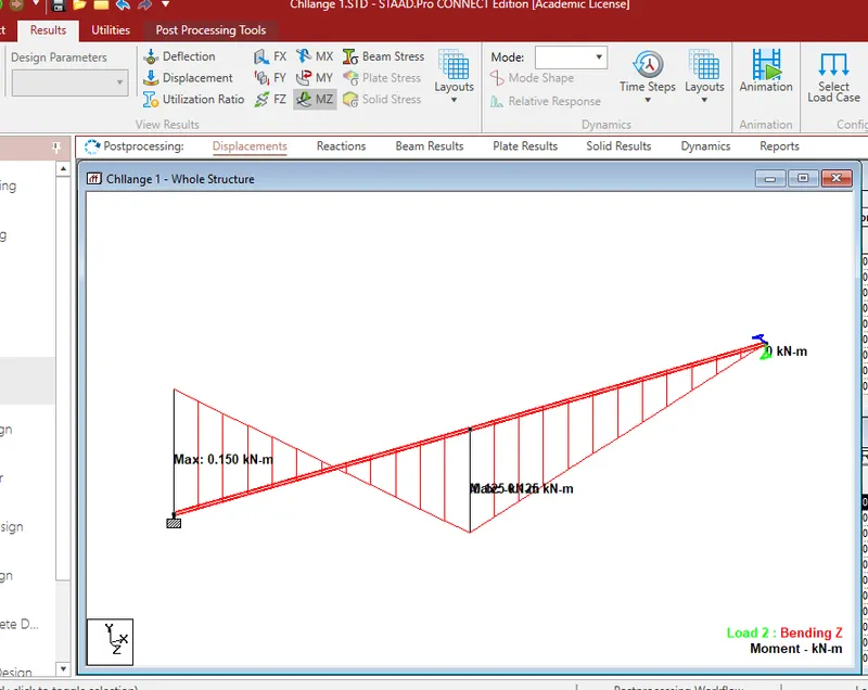
RESULTS: Draw Sfd and Bmd for beam with applying point load 50kN at centre with fixed and roller support
Beam
SFD
BMD