Week 1 Challenge
- 1. Write the steps involved to upload a .std file through web mail?
Answers :
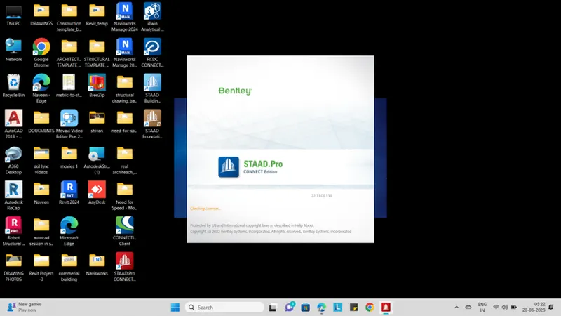
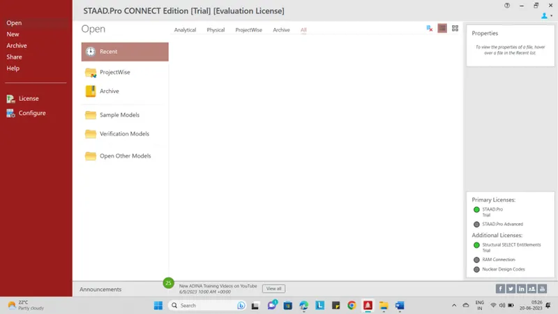
- Open PRO software in your system
- Go to “HOME” page
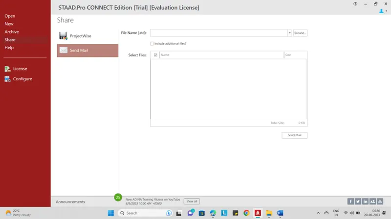
- Click “SHARE” button
- Go to “SEND MAIL “ option
- Click “BROWSE “ option
- Select “STAAD.PRO” file
- Finally click “SEND MAIL” option
2. Name the different materials that can be designed using STAAD Pro.
Answers :
Different Materials that can be designed Using STAAD.PRO are as below .
- Concrete
- Aluminium
- Steel
- Timber
- Composite section
3.Is it possible to capture images in STAAD Pro? If yes how?
Answers :
- Yes , it’s Possible to capture in Stad.pro
- Open PRO software in your system
- Go to “HOME” page
- Click “NEW” and “CREATE”
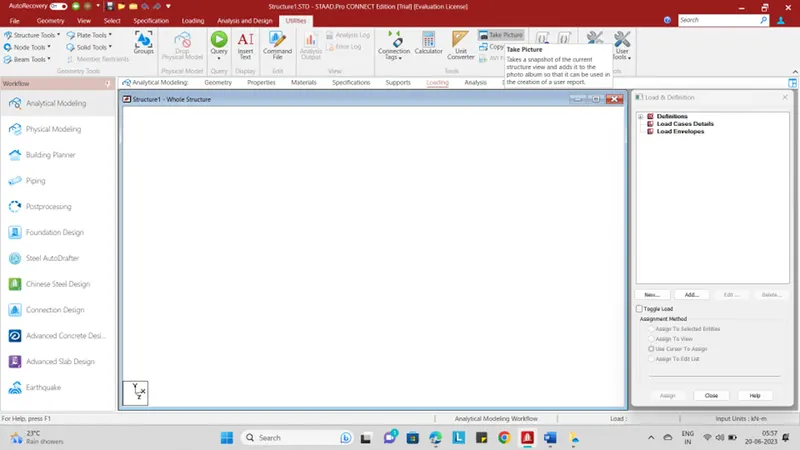
- Go to “UTILITIES” option
- There u have option called “TAKE PICTURE” option
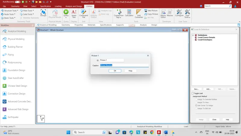
- Once you clicked “TAKE PICTURE” option u will get another Dialog box called “PICTURE -1”
- It will show “CAPTION “ also
- Name the three ways by which you can create a model.
ANSWERS:
- Analytical Model
- Physical Model
- Building planner Model
- Write the steps followed to assign properties in a model.
ANSWERS :
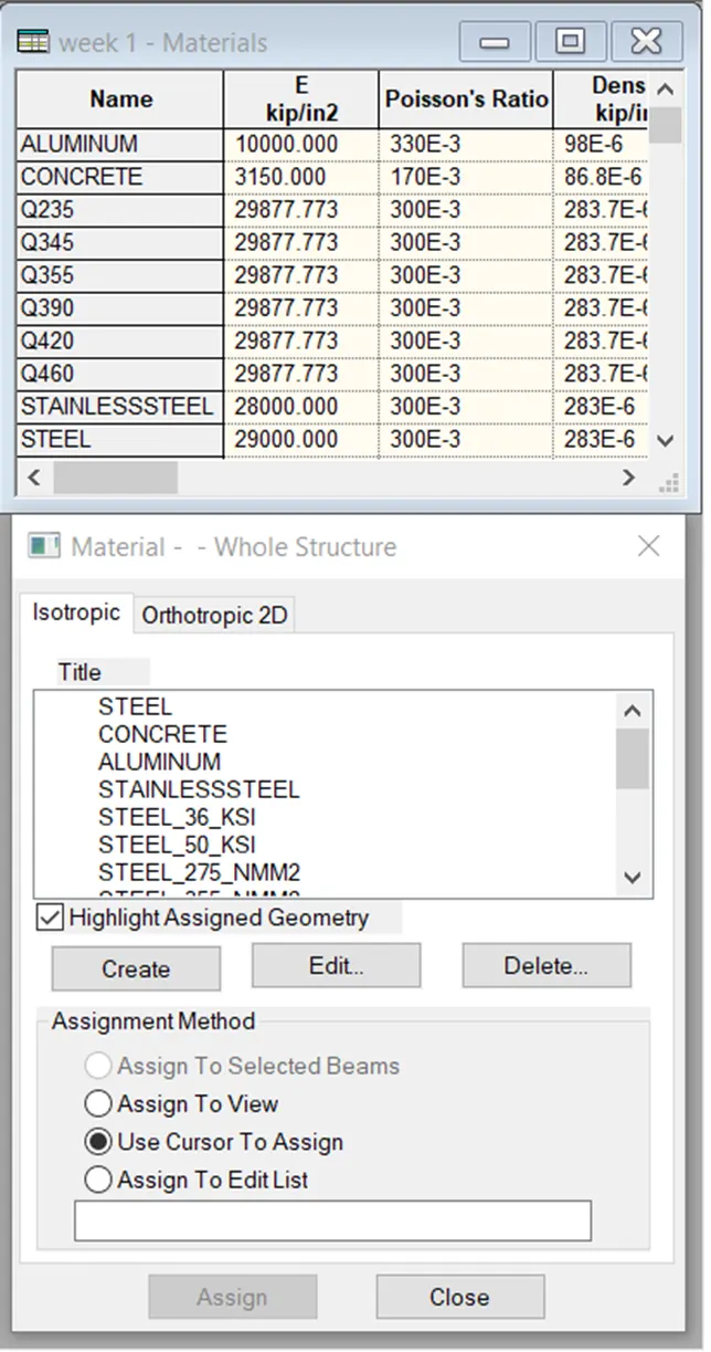
- Go to the “PROPERTIES MODEL”
- Click “MATERIAL “
- Select a desired material from the list
- Concrete , steel , aluminium ,stainless steel,
- Than check the assignment method based on your preference like use cursor / assign to etc.,
- After checking the radio button , go head and assign the material property to your model
- 1. Name any six design parameter involved in RCC design.
ANSWERS :
The six design parameter involved in RCC design are as below.
- Clear cover
- FC compressive strength of concrete
- FY tensile strength of steel
- Max main dia of bar
- Code of practice
- End concrete Design
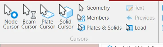
- What are the different cursor types available in STAAD Pro?
ANSWERS:
- Nodes Cursor
- Plates Cursor
- Beams Cursor
- Plates and solid Cursor
- Loads Cursor
- Solids Cursor
- Physical Member cursor
- Geometry Cursor
3. How will you generate different views for a model? State the steps involved.
ANSWERS :
- Open PRO software in your system
- Go to “HOME” page
- Click “NEW” and “CREATE”
- Go to “VIEW” tap
- The views are mentioned below :
- Top view
- Isometric View
- Front View
- Left View
- Right View
- Back View
- Bottom View
- Explain the procedure to define a “Simply Supported” condition in STAAD Pro
ANSWERS :
- Go to “Support” Command in the “TOOL PALET” command
- Click on “CREATE SUPPORT” command
- There we can get option like fixed support , PIN support
- Fixed but
- Enforced but support
- Cable support
- Inclined support
- Name any five topics that you will include while creating DBR.
DBR- DESIGN BASIS REPORT
DBR basically is a document that as stern data regarding the project .
It helps you where the project is located ,who the client is and what is the general specification of the project .it also give you the data that as consider while designing the building .
This data comprises speciation of the building ,
- Name of the project and location of the project
- Structural layout
- Introduction to the construction methodology
- Quality assurance and Quantity control
- Budget of the project
- Describe the term “Multi material design” of STAAD Pro.
ANSWERS:
- It is used for 3d model generation ,analysis and multi – martial design
- The STAAD.PRO supports several steel ,concrete , timber material in sperate member
- The sperate member will coordinate and formed into structure .
- 1. Name the structure systems in STAAD Pro? Explain each system?
ANSWERS :
The structure systems in STADD.PRO are :
- Space frames
- Plane Frames
- Trusses
EXPLAINATION :
- Space frames :
The spaces frames are the three -dimensional truss like structures that is designed to carry loads for longer spans without any intermediate support.
The space frame structures are light -weight in nature and it is structurally effective . it has low transportation cost.
- PLANE FRAMES :
Plane frames are RCC or steel frame structures . it is a two dimensional structure which is construed with straight elements which are connected by the rigid or the hinged connections.
3.TRUSSES :
Trusses are created by arranging the structural elements in the triangle forms which can take loads both compression and tension
- Explain the coordinate system adopted in STAAD Pro software.
ANSWERS :
The co-ordinate system that are adopted in STAAD.PRO software are X,Y and Z co-ordinates
So basically the co-ordinate system adopted in STAAD PRO are :
GLOBAL AXIS : Mainly global axis are fixed in the co-ordinate system .
LOCAL AXIS : Local axis is variable in nature . we can change local axis but not global axis
As STAAD.PRO software . basically it uses a conventional cartesian co-ordinate system , and in this system Y is a global axis which is upward direction . we can say that the height of the building is always parallel to the global Y-axis .
- Elaborate DBR and its uses.
ANSWERS :
The DBR (DESIGN BASIS REPORT) is a project management document which is consist of various information regarding the construction of structure . the DBR is detailed report which tells the minute details of the ongoing construction work .
It defines the final stage in the process of defining the client requirement for the construction work . this report basically consist of all the major and important structural details that is relevant or we can say that related to the project like description of the client , site information , special requirements if any the technical requirements ,components required the project , requirements and other issue related to the construction
- Explain the different types of analysis options in STAAD pro.
ANSWERS :
- Linear Elastic Analysis
- P- Delta Analysis
- Buckling Analysis
- Pushover Analysis
- Explain the difference between Fixed and Fixed But condition.
ANSWERS:
Fixed condition :-
Fixed condition in the STAAD .PRO software is condition where all the degrees of freedom that is horizontal or vertical or moment are fixed or we can say these condition are restrained we cannot change accordingly . those condition we can say that fixed condition
Fixed but -Condition :-
The fixed -end condition we can say that this condition can be customized its end condition accordingly . in this condition we can change the end condition , it is not restrained . we can release some of the required degree of freedom .
Practical
1. Create a STAAD Model with the following Specification
a. A beam of span 16m
b. Support : Fixed on one end and Roller support(Horizontal) on the other end
c. A point load of 50 kN at the mid-point
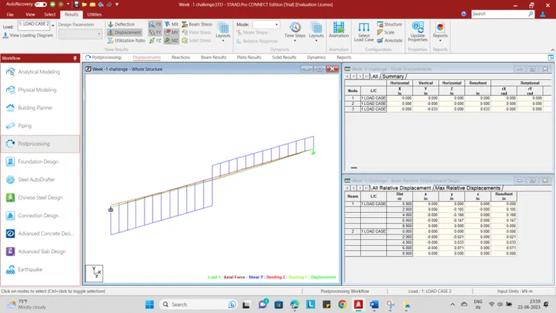
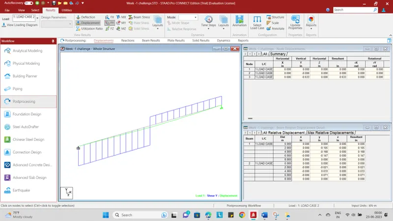
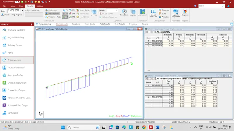
d. Draw SFD and BMD using software
AIM :
To Create a STAAD Model with the following Specification
PROCEDURE:
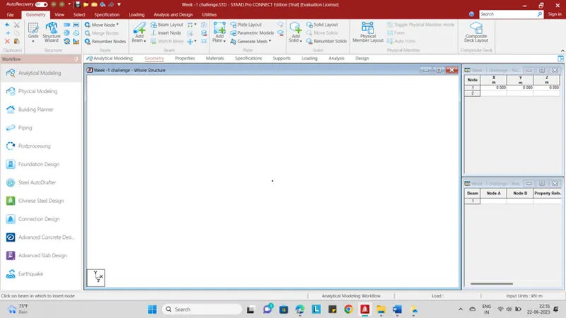
STEP -1 :
- Open PRO software
- Click “NEW” option
- Enter File Name as “Challenge -1”
- Select the type as “ANALYTICAL”
- Select the unit as “METRIC”
- Enter Title as “ A beam of span 16m”
- Click “CREATE” option
STEP -2 :
- Go to “NODES” option
- Enter First “X-0,Y-0,Z-0”
- Right click your mouse
- Go to “select Cursor”
- Select “NODE CURSOR” option
- Ctrl +C and Ctrl+V
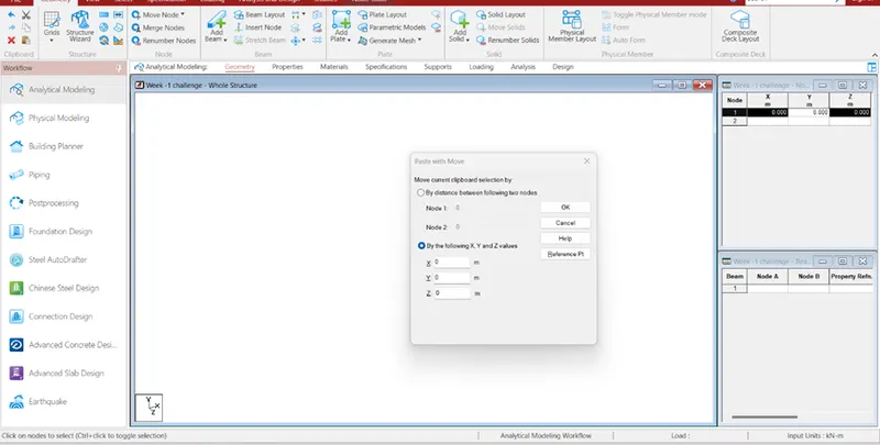
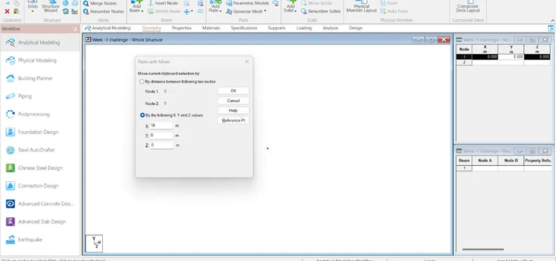
- U Will get dialog box called “PAST WITH MOVE”
- Give value in “X-16m”
- Click “OK”
- U will get another point distance of 16m
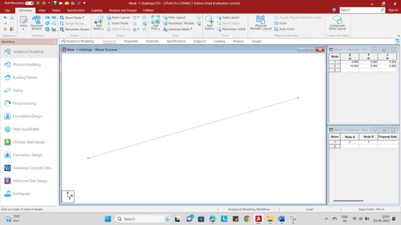
- Go to “GEOMETRY” tap
- Click “ADD BEAM” option
- Click One point to Another point
- Click “ESC”
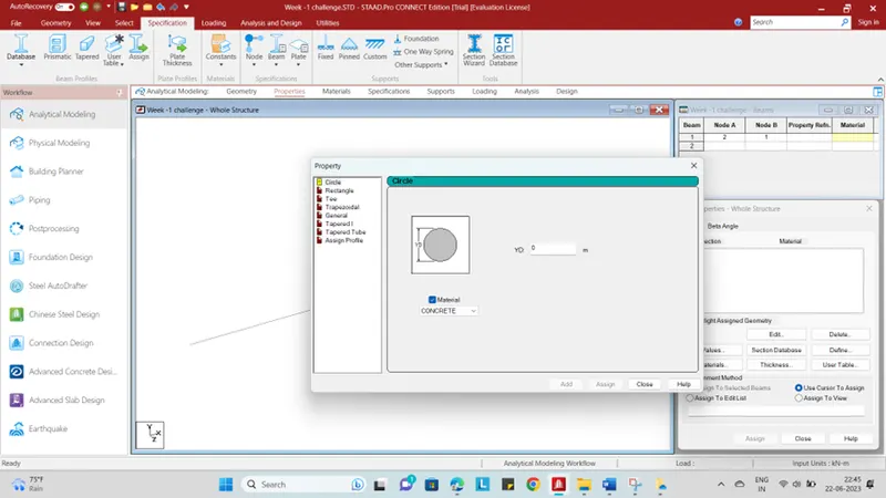
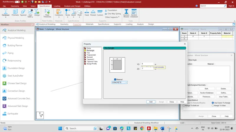
- Go to “PROPERTIES”
- Than u will get dialog box in your right side
- Click “DEFINE” option
- Then u will get dialog box called “PROPRTIES”
- Than give a value as “YD-.6” and “ZD-.3”
- Click “ADD” and “CLOSE” option
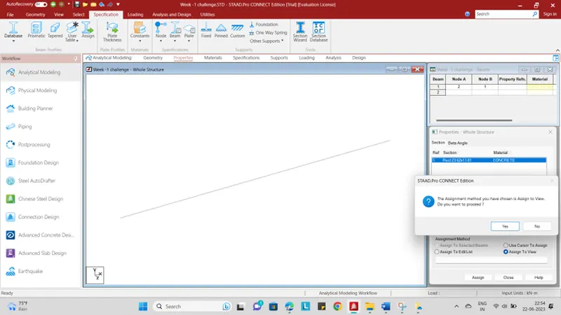
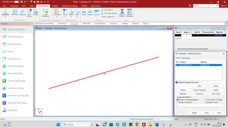
- Than select “ASSIGN TO VIEW”
- Than “ASSIGN”
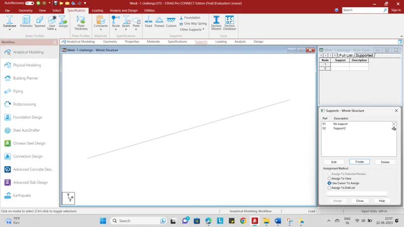
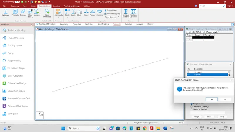
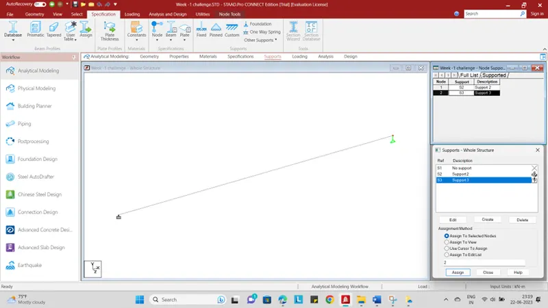
- Go to “SUPPORTS” option
- Click “CREATE” option
- And click “OK”
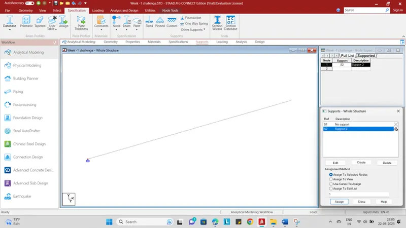
- Select “SUPPORT 2” and Select the “POINT”
- Select assign method as “ASSIGN TO SELECTED NODES”
- Click “ASSIGN” and
- Click “OK”
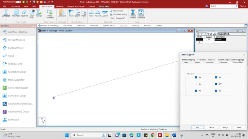
- Again click “CREATE” option
- U will get dialog box called “CREATE SUPPORT” option
- Go to the “ENFORCED BUT “
- Select “FX” and “FZ”
- Same like “MX,MY,MZ”
- Click “ADD” option
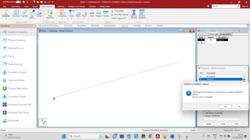
- Than select 2nd support
- Than click “ASSIGN”
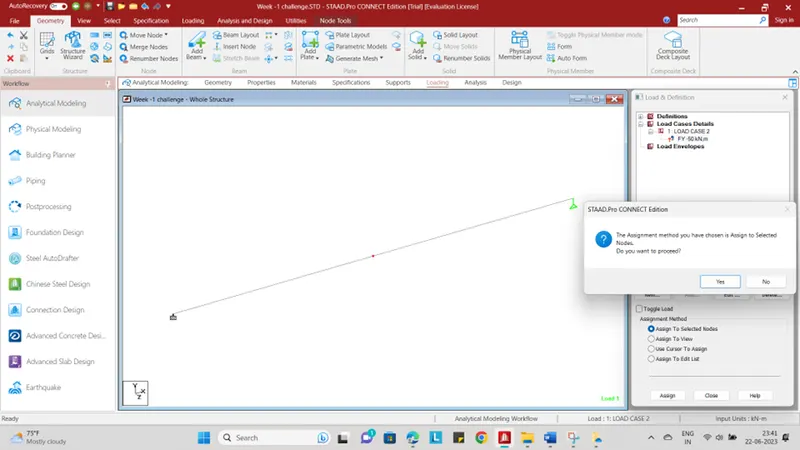
- Click “YES”
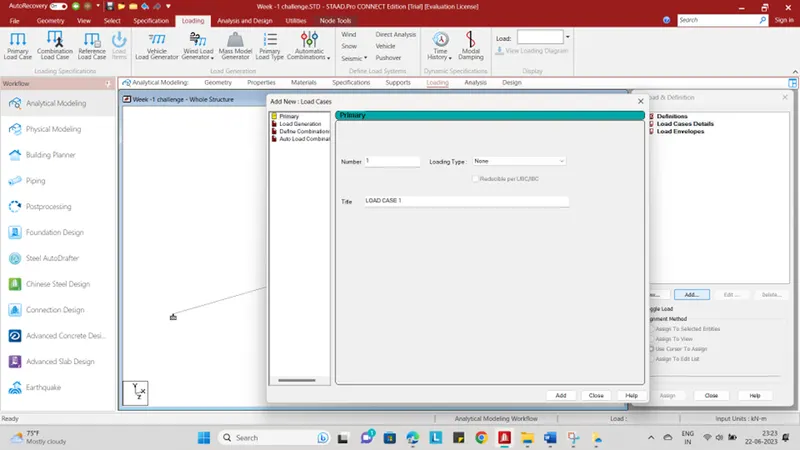
- Go to “LOADING “ option
- Than click “LOAD CASES DETAILS “
- Click “ADD” option
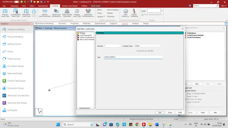
- Select “DEAD LOAD “
- Type “LOAD CASES 2”
- Click “ADD” option and “CLOSE”
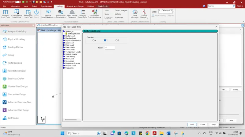
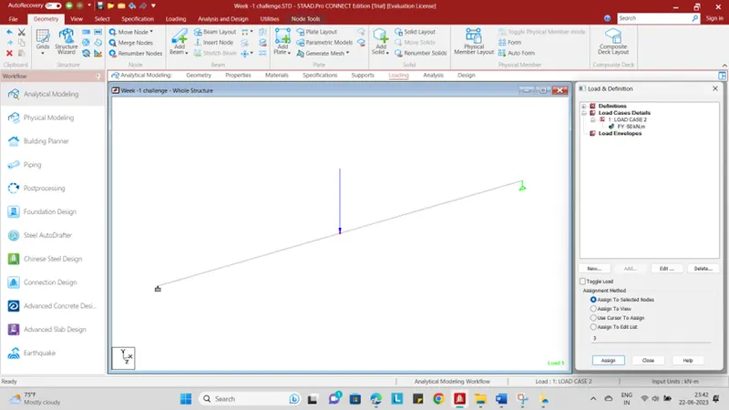
- Click “DEAD” and “ADD” option
- Than click “NODE” option
- Give value as “FY-50”
- Click “ADD” option and “CLOSE”
- Select the “NODE” option
STEP :3
- Go to “GEOMETRY”
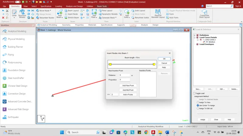
- Click “INSERT NODE” option
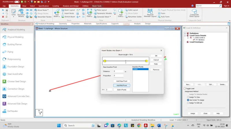
- U will get dialog box called “INSERT NODES INTO BEAM -1”
- Than click “ADD MID POINT “ option
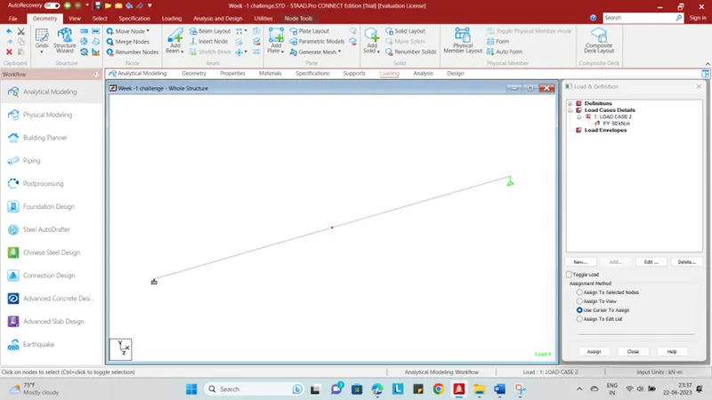
- Click “OK”
- Right click your mouse
- Go to “select Cursor”
- Select “NODE CURSOR” option
- The mid point will be reflect your system
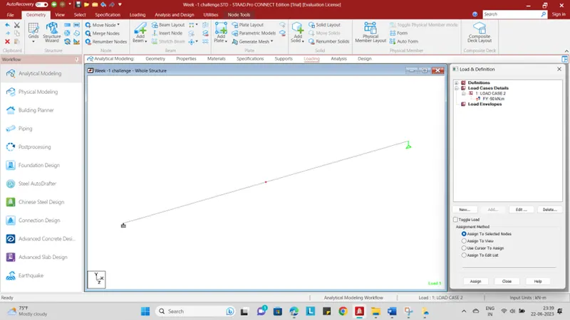
- Select the “MID POINT “
- Click “ASSIGN TO SELECTED NODES”
- Click “YES”
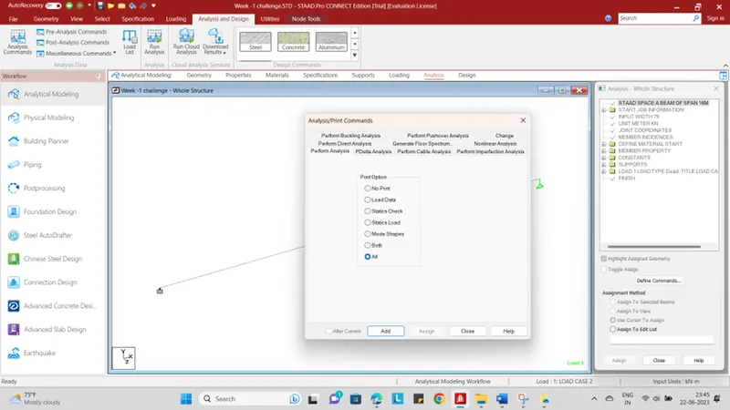
- Go to “ANALYSIS AND DESIGN” tap
- Click “ANALYSIS COMMANDS” option
- U will get dialog box called “ANALYSIS/ PRINT COMMANDS”
- Click “ALL” option and “CLOSE”
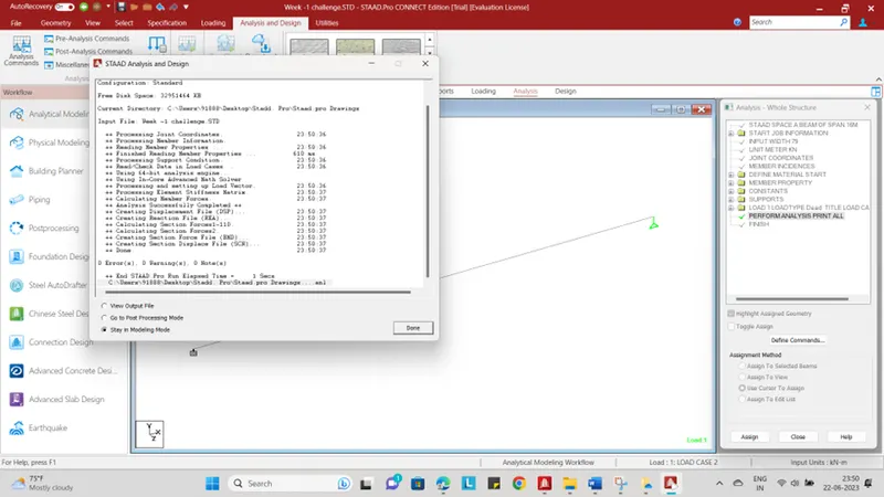
- Go to “RUN ANALYSIS” tap
- After that u will get dialog box called “STAAD Analysis and Design”
- There is no “ERROR, WARNING, NOTES”
- Click “DONE” option
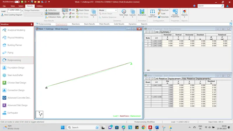
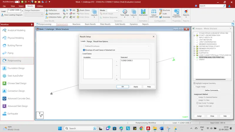
- Go to the “POSTPROCESSING” option
- U will get dialog box called “RESULT SETUP”
- once you click
- your FINAL RESULT WILL BE READY…!
RESULT :