Week 1 Challenge
1. AIM :
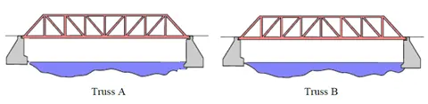
Out of the two through type truss systems shown below, which is the most efficient in carrying gravity load.
INTRODUCTION :
We can clearly see that the Truss A is "Pratt truss" & Truss B is "Howe truss".
PROCEDURE :
Pratt Truss
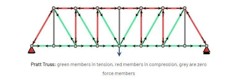
Pratt has diagonals in tension, verticals in compression, except for the hip verticals immediately adjacent to the inclined end posts of the bridge. Pratt truss is one of the most common forms of truss and is made up of vertical and diagonal members that form an ’N’ shape or pattern. The diagonal members are arranged so that they only develop tensile forces. As such, they can be designed to resist axial tension only, avoiding the need for a compression buckling analysis. The vertical members in a Pratt truss develop compression forces.
Howe Truss
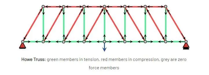
A Howe truss is a truss bridge consisting of chords, verticals, and diagonals whose vertical members are in tension and whose diagonal members are in compression. Howe trusses are essentially the opposite of Pratt trusses in terms of geometry. In fact, looking at a Pratt truss upside-down will visualize a Howe truss of sorts. The entire structure is still relatively the same, but the diagonal braces are now occupying the opposite or the unoccupied joints. This switch in position of the diagonal members has a very important effect structurally.
- The main differences are that the Pratt truss has no force on the ends and the compression members are vertical.
- The Howe truss has no force on the center and the tension members are vertical instead.
- Pratt trusses have their vertical members in compression and diagonal members in tension upon the application of gravity loads at the joints of the top chord. For Howe trusses, the reverse becomes true as diagonal members are now in compression, while the vertical loads are in tension.
- Pratt trusses can have more unloaded members than Howe trusses.
Result :
HENCE "Pratt trusses(Truss A)" is most efficient in carrying gravity loads.
2. AIM :
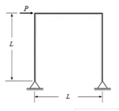
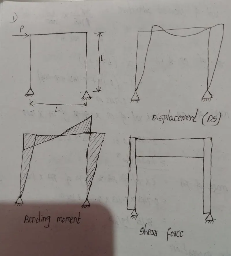
For the beam & Frame below draw deflected shape and bending moment drawing. E & I are constants.
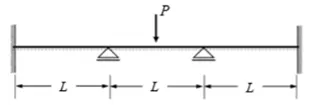
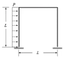
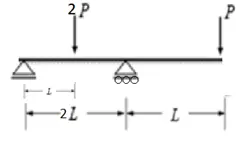
INTRODUCTION :
- When a structural element is subjected to bending, it curves causing one side to stretch and the other to contract.
PROCEDURE :
- Shear force and bending moment diagrams are analytical tools used in conjunction with structural analysis to help perform structural design by determining the value of shear forces and bending moments at a given point of a structural element such as a beam.
- A bending moment or a shear force diagram is a graph typically drawn over a beam with abscissa representing the beam cross section.
Result :
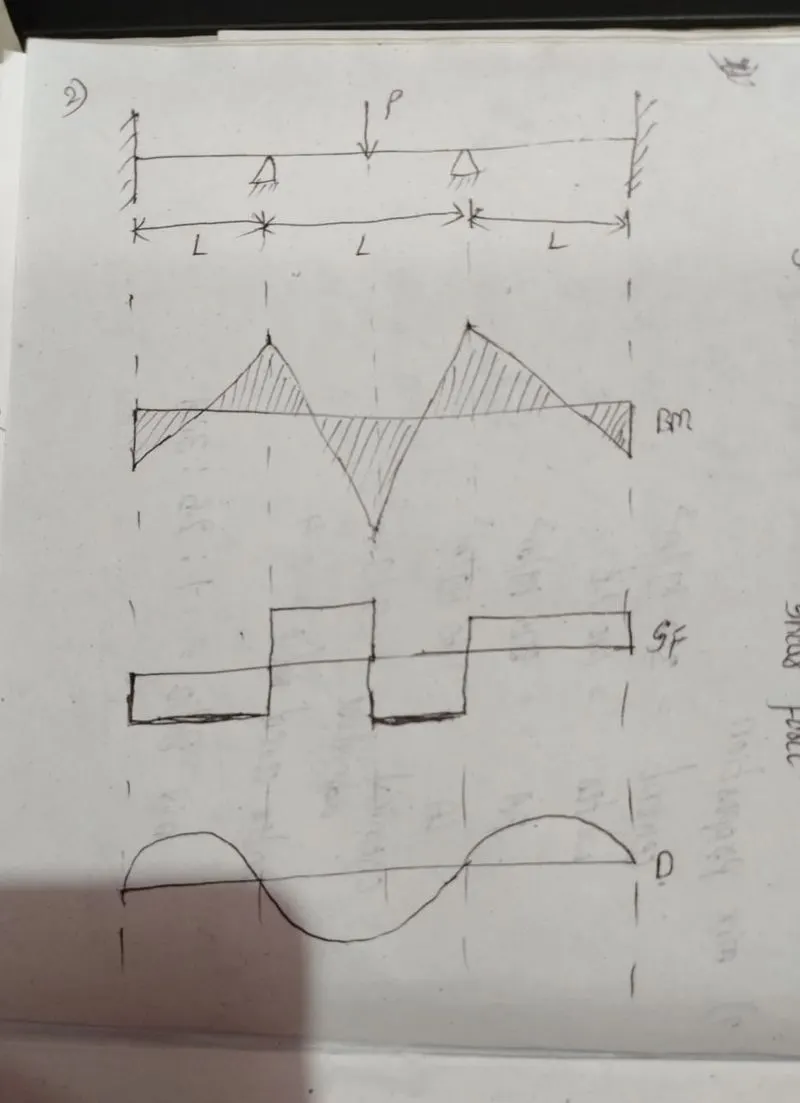
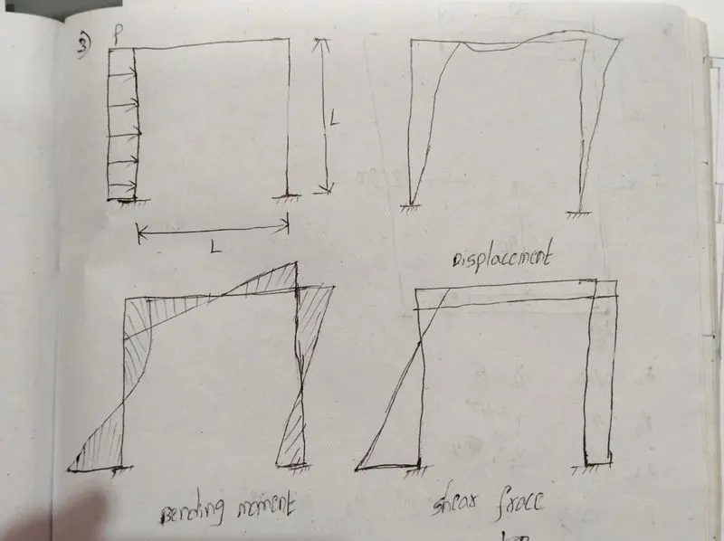
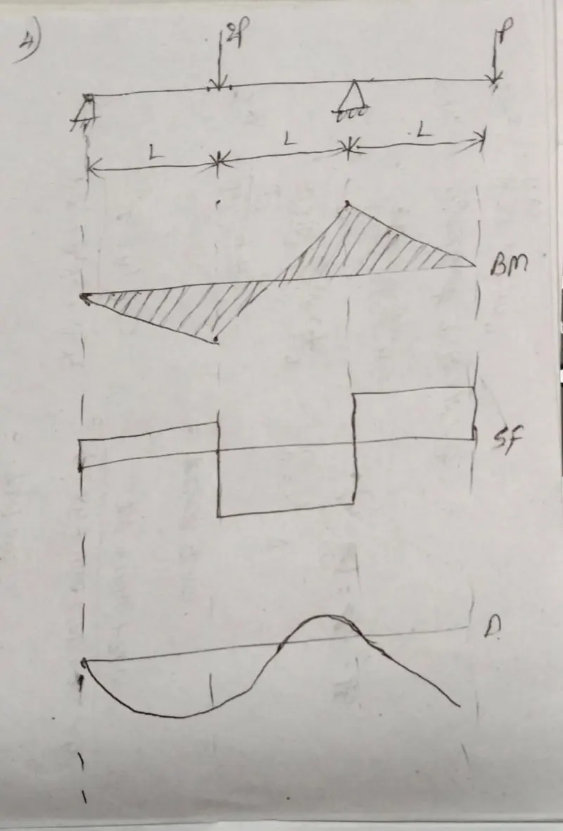
3. AIM :
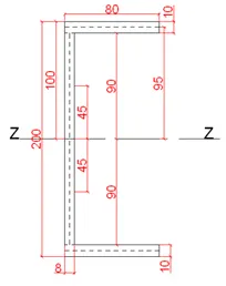
To Determine MOI, Weight, C/S area of sections below
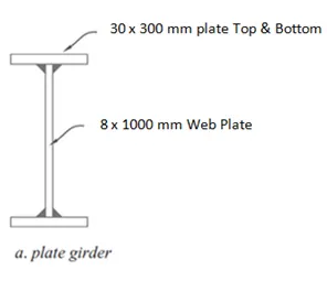
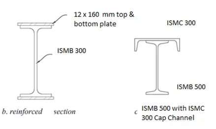
INTRODUCTION :
Quantitative measure of the rotational inertia of a body i.e., the opposition that the body exhibits to having its speed of rotation about an axis altered by the application of a torque (turning force). The axis may be internal or external and may or may not be fixed.
PROCEDURE :
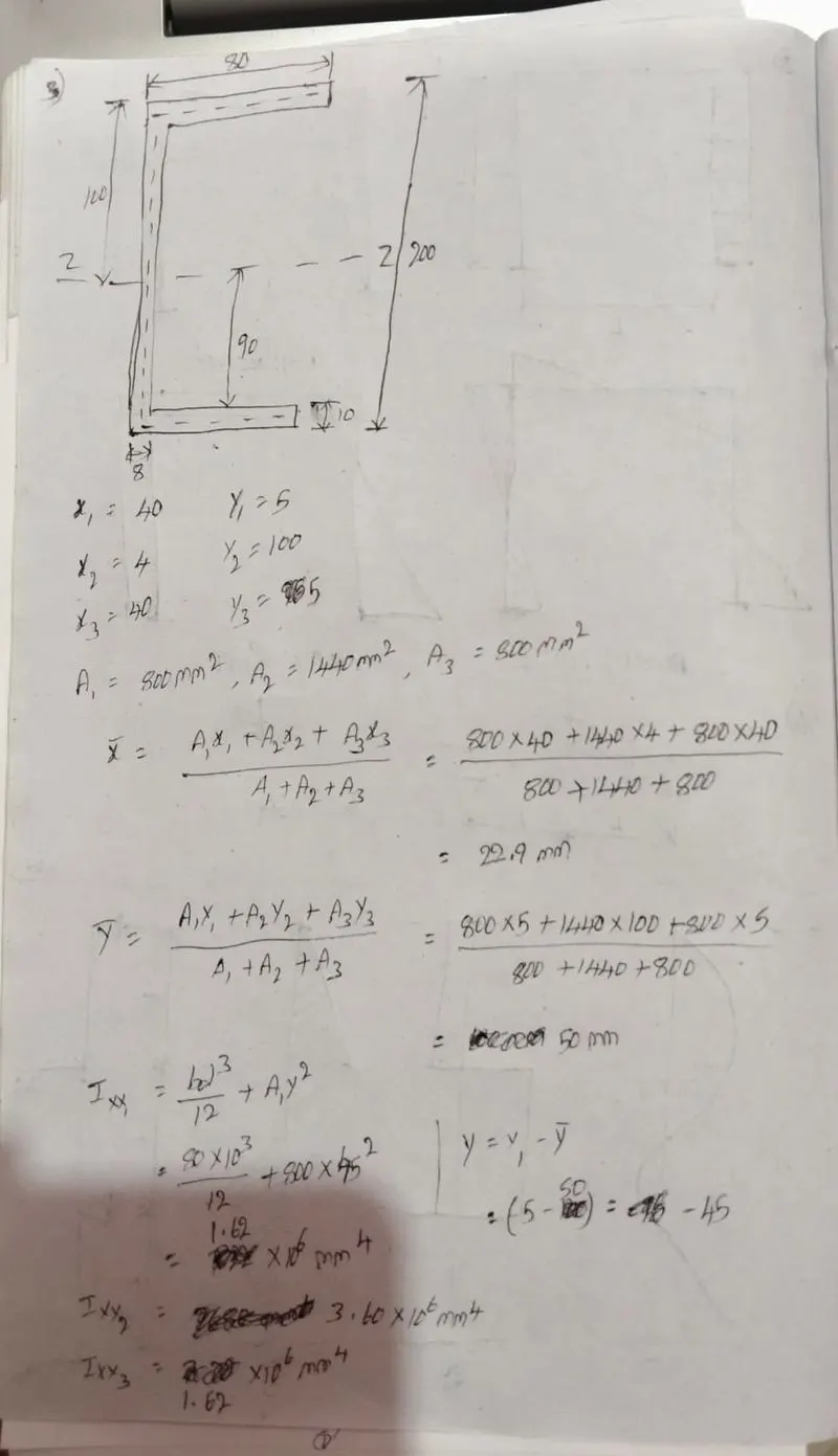
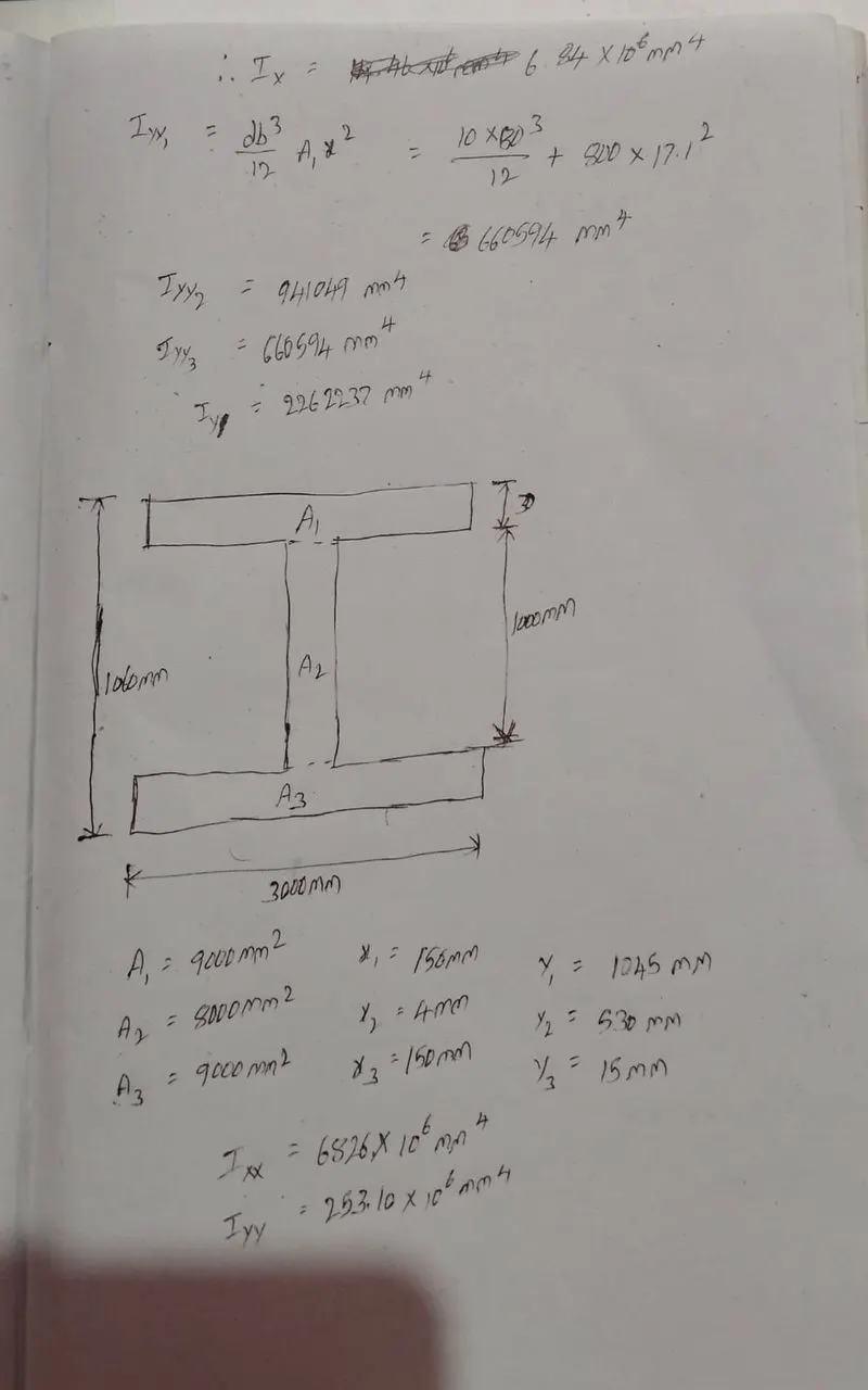
Result :
1. Ix = 6.84 x 10 6 mm4
Iy = 2262237 mm4
2. Ix = 6826 x 10 6 mm4
Iy = 253.10 x 10 6 mm4
4. AIM :
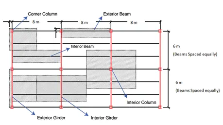
For the floor framing below, Calculate the load on interior beam, Exterior beam, Interior Girder and exterior girder having Floor Load of 10kN/m2
INTRODUCTION :
- The beam's distributed load is computed by multiplying the segment area by the slab's unit load divided by the beam length. For an interior beam, the portion of the other side's slab weight is estimated in a similar way and added to the previous one, i.e., the slab's load from the other side of the beam.
- The loads applied to the beam produce reactive forces at the support points of the beam. The structural element which resists the forces transversely or laterally applied to the axis is called a beam. In it, the loads act opposite to the longitudinal axis, which creates shear forces and bending moment.
PROCEDURE :
Floor Load - 10kN/m2
Tributary width of exterior grider - 0.5(0+8) = 4m
Tributary width of interior grider - 0.5(8+8) = 8m
Tributary width of exterior Beam - 0.5(0+2) = 1m
Tributary width of interior Beam - 0.5(2+2) = 2m
Load on beam = Tributary width x Floor Load
Load on exterior grider = 4 x 10 = 40 KN/m
Load on interior grider = 8 x 10 = 80 KN/m
Load on exterior beam = 1 x 10 = 10 KN/m
Load on interior beam = 2 x 10 = 20 KN/m
Result :
Load on exterior grider = 4 x 10 = 40 KN/m
Load on interior grider = 8 x 10 = 80 KN/m
Load on exterior beam = 1 x 10 = 10 KN/m
Load on interior beam = 2 x 10 = 20 KN/m
5. AIM :
Assuming a bridge, made of steel, with an initial total length of 2000 m at -20 ºC, calculate the length difference at 40 ºC and its total length.
INTRODUCTION :
Steel is an alloy made up of iron with added carbon to improve its strength and fracture resistance compared to other forms of iron.
PROCEDURE :
initial total length of 2000 m
temparature = -20 ºC
calculate the length difference at 40 ºC and its total length.
Coefficient of Thermal expansion of steel = 12x10-6/°C
Change in length = coifficient of thermal expansion x original length x change in temparature
= 12x10-6/°C x 2000 x 20
= 0.48 m
length difference at 40 ºC = 0.48 m
Total length = 2000.48 m
Result :
length difference at 40 ºC = 0.48 m
Total length = 2000.48 m