Creation of geometries by Coordinate system methods using AutoCad
AIM :
a. Create the geometries from P1 to P2 using all the coordinates system methods. You need to use the Line tool to create the geometries. Where required you need to use the circle tool.
b. Draw the profile and the trusses using any coordinate system methods. The dimensions are there for references.
INTRODUCTION :
In AutoCad there are two co-ordinate systems i.e cartesian and polar.
Co-ordinate system : A coordinate system is a system that uses one or more numbers or co-ordinate, to uniquely determine the position of the points are other geometric elements. The values of coordinates in the command line and entry coordinates using Dynamic input.
There are three types of co-ordinate systems they are
1. Absolute coordinate system
2. Relative co-ordinate system
a. Relative rectangular coordinates
b. Relative polar coordinates
3. Direct distance entry
PROCEDURE :
- Go to menu, select AutoCAD 2023.
- Click on start drawing
- In the command line type STARTUP
- Enter new value of startup 1
- Go to new application Menu and select NEW
- Next select the Decimal unit system for the Advanced setup option.
- Set the limits by entering LIMITS in the command tab the lower left corner is specified as 0,0 and the upper right corner is specified as 100, 100.
a. To create the geometries from P1 to P2 using all the coordinates system methods.
1. Drafting the geometry for P1 drawing by using All coordinates system methods :
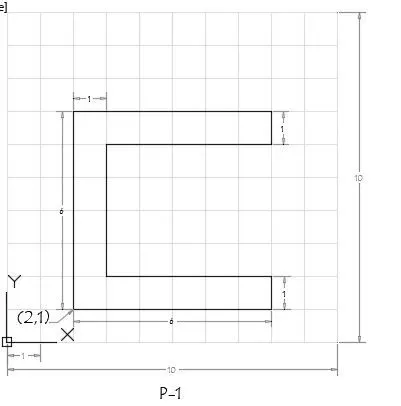
a. Absolute coordinate system
- Select the line tool from the ribon tab.
- Specify the starting co-ordinate of point 1 as 2,1
- Specify the next co-ordinate of point 2 as 8,1.
- Specify the next co-ordinate of point 3 as 8,2
- Specify the next co-ordinate of point 4 as 3,2
- Specify the next co-ordinate of point 5 as 3,6
- Specify the next co-ordinate of point 6 as 8,6
- Specify the next co-ordinate of point 7 as 8,7
- Specify the next co-ordinate of point 8 as 2,7
- Then for the last point click close on the command line.
b. Relative rectangular coordinate system
- Select the line tool from the ribon tab.
- Specify the starting co-ordinate of point 1 as 2,1
- Specify the next co-ordinate of point 2 as @6,0.
- Specify the next co-ordinate of point 3 as @0,1
- Specify the next co-ordinate of point 4 as @-5,0
- Specify the next co-ordinate of point 5 as @0,4
- Specify the next co-ordinate of point 6 as @5,0
- Specify the next co-ordinate of point 7 as @0,1
- Specify the next co-ordinate of point 8 as @-6,0
- Then for the last point click close on the command line.
c. Relative polar coordinate system
- Select the line tool from the ribon tab.
- Specify the starting co-ordinate of point 1 as 2,1
- Specify the next co-ordinate of point 2 as @6<0.
- Specify the next co-ordinate of point 3 as @1<90
- Specify the next co-ordinate of point 4 as @5<180
- Specify the next co-ordinate of point 5 as @4<90
- Specify the next co-ordinate of point 6 as @5<0
- Specify the next co-ordinate of point 7 as @1<90
- Specify the next co-ordinate of point 8 as @6<180
- Then for the last point click close on the command line.
d. Direct distance entry method
- Select the line tool from the ribon tab.
- Specify the starting co-ordinate of point 1 as 2,1
- Enter the length of point 2 as 6 in the command line towards the +ve x-axis
- Enter the length of point 3 as 1 in the command line towards the +ve y-axis
- Enter the length of point 4 as 5 in the command line towards the -ve x-axis
- Enter the length of point 5 as 4 in the command line towards the +ve y-axis
- Enter the length of point 6 as 5 in the command line towards the +ve x-axis
- Enter the length of point 7 as 1 in the command line towards the +ve y-axis
- Enter the length of point 8 as 6 in the command line towards the -ve x-axis
- Then for the last point click close on the command line.
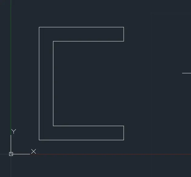
Result :
2. Drafting the geometry for P2 drawing by using All coordinates system methods :
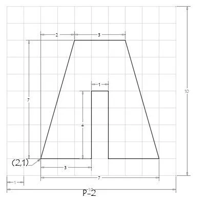
a. Absolute coordinate system
- Select the line tool from the ribon tab.
- Specify the starting co-ordinate of point 1 as 2,1
- Specify the next co-ordinate of point 2 as 5,1.
- Specify the next co-ordinate of point 3 as 5,5
- Specify the next co-ordinate of point 4 as 6,5
- Specify the next co-ordinate of point 5 as 6,1
- Specify the next co-ordinate of point 6 as 9,1
- Specify the next co-ordinate of point 7 as 7,8
- Specify the next co-ordinate of point 8 as 4,8
- Then for the last point click close on the command line.
b. Relative rectangular coordinate system
- Select the line tool from the ribon tab.
- Specify the starting co-ordinate of point 1 as 2,1
- Specify the next co-ordinate of point 2 as @3,0.
- Specify the next co-ordinate of point 3 as @0,4
- Specify the next co-ordinate of point 4 as @1,0
- Specify the next co-ordinate of point 5 as @0,-4
- Specify the next co-ordinate of point 6 as @3,0
- Specify the next co-ordinate of point 7 as @-2,7
- Specify the next co-ordinate of point 8 as @-3,0
- Then for the last point click close on the command line.
c. Relative polar coordinate system
- Select the line tool from the ribon tab.
- Specify the starting co-ordinate of point 1 as 2,1
- Specify the next co-ordinate of point 2 as @3<0.
- Specify the next co-ordinate of point 3 as @4<90
- Specify the next co-ordinate of point 4 as @1<90
- Specify the next co-ordinate of point 5 as @4<270
- Specify the next co-ordinate of point 6 as @3<0
- Specify the next co-ordinate of point 7 as @7<106
- Specify the next co-ordinate of point 8 as @3<180
- Then for the last point click close on the command line.
d. Direct distance entry method
- Select the line tool from the ribon tab.
- Specify the starting co-ordinate of point 1 as 2,1
- Enter the length of point 2 as 3 in the command line towards the +ve x-axis
- Enter the length of point 3 as 4 in the command line towards the +ve y-axis
- Enter the length of point 4 as 1 in the command line towards the -ve x-axis
- Enter the length of point 5 as 4 in the command line towards the +ve y-axis
- Enter the length of point 6 as 3 in the command line towards the +ve x-axis
- Enter the length of point 7 as 7 in the command line at an angle of <106 from the +ve x-axis while keeping polar tracking on.
- Enter the length of point 8 as 3 in the command line towards the -ve x-axis
- Then for the last point click close on the command line.
Result :
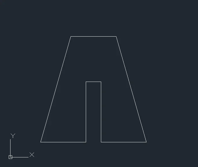
3. Drafting the geometry for P4 drawing by using Absolute Coordinate System :
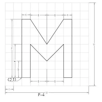
STEPS :
- Select the line tool from the ribon tab.
- Specify the starting co-ordinate of point 1 as 2,1
- Specify the next co-ordinate of point 2 as 3,1.
- Specify the next co-ordinate of point 3 as 3,5
- Specify the next co-ordinate of point 4 as 5,3
- Specify the next co-ordinate of point 5 as 7,5
- Specify the next co-ordinate of point 6 as 7,1
- Specify the next co-ordinate of point 7 as 8,1
- Specify the next co-ordinate of point 8 as 8,8
- Specify the next co-ordinate of point 9 as 7,8
- Specify the next co-ordinate of point 10 as 5,5
- Specify the next co-ordinate of point 11 as 3,8
- Specify the next co-ordinate of point 12 as 2,8
- Then for the last point click close on the command line.
Result :
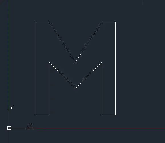
4. Drafting the geometry for P5 drawing by using Relative Rectangular Coordinate System :
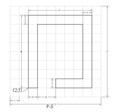
STEPS :
- Select the line tool from the ribon tab.
- Specify the starting co-ordinate of point 1 as 2,1
- Specify the next co-ordinate of point 2 as @1,0.
- Specify the next co-ordinate of point 3 as @0,7
- Specify the next co-ordinate of point 4 as @5,0
- Specify the next co-ordinate of point 5 as @0,-6
- Specify the next co-ordinate of point 6 as @-3,0
- Specify the next co-ordinate of point 7 as @0,-1
- Specify the next co-ordinate of point 8 as @4,0
- Specify the next co-ordinate of point 9 as @0,8
- Specify the next co-ordinate of point 10 as @-7,0
- Then for the last point click close on the command line.
Result :
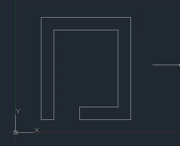
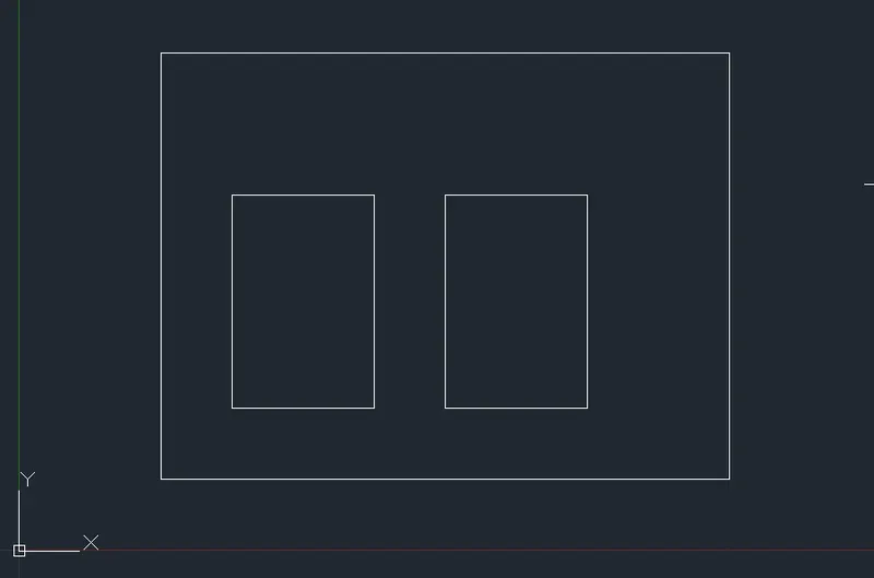
5. Drafting the geometry for P7 by using Absolute Coordinate System :
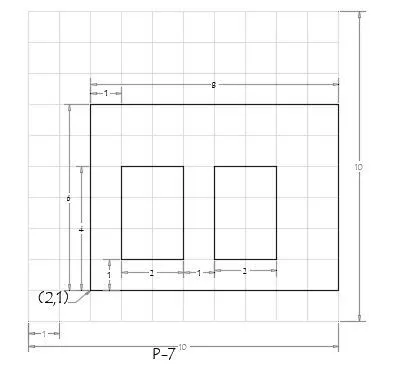
STEPS :
- Select the line tool from the ribon tab.
- Specify the starting co-ordinate of point 1 as 2,1
- Specify the next co-ordinate of point 2 as 10,1.
- Specify the next co-ordinate of point 3 as 10,7
- Specify the next co-ordinate of point 4 as 2,7
- Click 'Close' on the command line
- Select the line tool from the ribon tab.
- Specify the next co-ordinate of point 5 as 3,2
- Specify the next co-ordinate of point 6 as 5,2
- Specify the next co-ordinate of point 7 as 5,5
- Specify the next co-ordinate of point 8 as 3,5
- Click 'Close' on the command line
- Select the line tool from the ribon tab.
- Specify the next co-ordinate of point 9 as 6,2
- Specify the next co-ordinate of point 10 as 8,2
- Specify the next co-ordinate of point 11 as 8,5
- Specify the next co-ordinate of point 12 as 6,5
- Then for the last point click close on the command line.
Result :
6. Drafting the geometry for P8 by using Absolute Coordinate System :
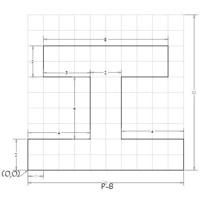
STEPS :
- Select the line tool from the ribon tab.
- Specify the starting co-ordinate of point 1 as 0,0
- Specify the next co-ordinate of point 2 as 10,0.
- Specify the next co-ordinate of point 3 as 10,2
- Specify the next co-ordinate of point 4 as 6,2
- Specify the next co-ordinate of point 5 as 6,6
- Specify the next co-ordinate of point 6 as 9,6
- Specify the next co-ordinate of point 7 as 9,8
- Specify the next co-ordinate of point 8 as 1,8
- Specify the next co-ordinate of point 9 as 1,6
- Specify the next co-ordinate of point 10 as 4,6
- Specify the next co-ordinate of point 11 as 4,2
- Specify the next co-ordinate of point 12 as 0,2
- Then for the last point click close on the command line.
Result :
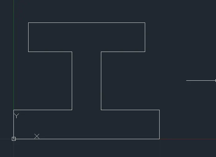
7. Drafting the geometry for P9 by using Absolute Coordinate System :
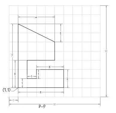
STEPS :
- Select the line tool from the ribon tab.
- Specify the starting co-ordinate of point 1 as 1,1
- Specify the next co-ordinate of point 2 as 6,1
- Specify the next co-ordinate of point 3 as 6,3
- Specify the next co-ordinate of point 4 as 3,3
- Specify the next co-ordinate of point 5 as 3,2
- Specify the next co-ordinate of point 6 as 2,2
- Specify the next co-ordinate of point 7 as 2,4
- Specify the next co-ordinate of point 8 as 5,4
- Specify the next co-ordinate of point 9 as 5,6
- Specify the next co-ordinate of point 10 as 1,8
- Then for the last point click close on the command line.
Result :
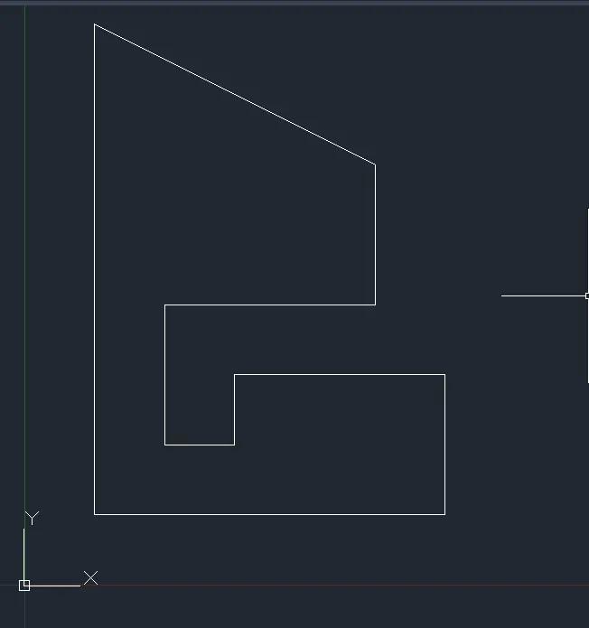
8. Drafting the geometry for P10 by using Absolute Coordinate System :
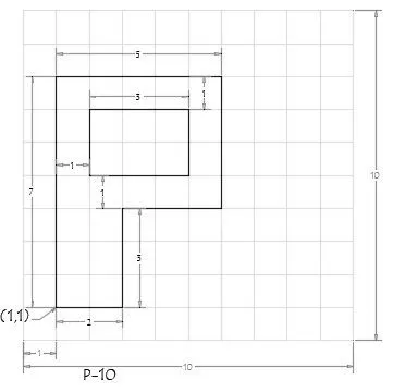
STEPS :
- Select the line tool from the ribon tab.
- Specify the starting co-ordinate of point 1 as 1,1
- Specify the next co-ordinate of point 2 as 3,1
- Specify the next co-ordinate of point 3 as 3,4
- Specify the next co-ordinate of point 4 as 6,4
- Specify the next co-ordinate of point 5 as 6,8
- Specify the next co-ordinate of point 6 as 1,8
- Click 'Close' on the command line
- Specify the next co-ordinate of point 7 as 2,5
- Specify the next co-ordinate of point 8 as 5,5
- Specify the next co-ordinate of point 9 as 5,7
- Specify the next co-ordinate of point 10 as 2,7
- Then for the last point click close on the command line.
Result :
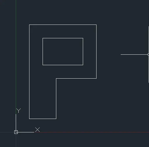
b. Draw the profile and the trusses using any coordinate system methods. The dimensions are there for references.
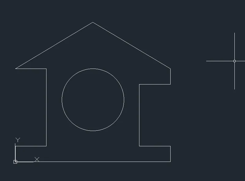
1. Drafting the Wood Profile as shown in the given picture by using Absolute Coordinate System :
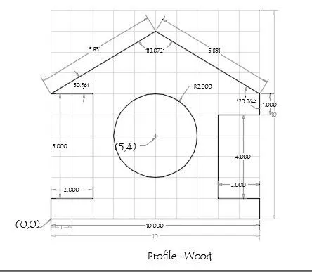
STEPS :
- Select the line tool from the ribon tab.
- Specify the starting co-ordinate of point 1 as 0,0
- Specify the next co-ordinate of point 2 as 10,0
- Specify the next co-ordinate of point 3 as 10,1
- Specify the next co-ordinate of point 4 as 8,1
- Specify the next co-ordinate of point 5 as 8,5
- Specify the next co-ordinate of point 6 as 10,5
- Specify the next co-ordinate of point 7 as 10,6
- Specify the next co-ordinate of point 8 as 5,9
- Specify the next co-ordinate of point 9 as 0,6
- Specify the next co-ordinate of point 10 as 2,6
- Specify the next co-ordinate of point 11 as 2,1
- Specify the next co-ordinate of point 12 as 0,1
- Then for the last point click close on the command line.
- Select the Circle tool by entering the 'Circle' command in the command tab
- Specify center point of the circle as 5,4
- Specify radius of the circle as 2
Result :
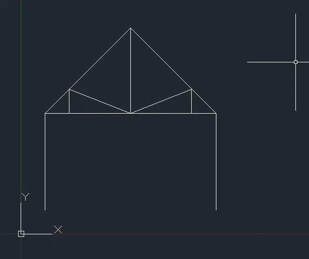
2. Drafting the Queen Post Truss as shown in the given picture by using Realtive Polar Coordinate System :
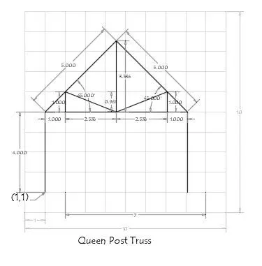
STEPS :
- Select the line tool from the ribon tab.
- Specify the starting co-ordinate of point 1 as 1,1
- Specify the next co-ordinate of point 2 as @4<90
- Specify the next co-ordinate of point 3 as @5<45
- Specify the next co-ordinate of point 4 as @5<315
- Specify the next co-ordinate of point 5 as @4<270
- Click 'Esc' to cancel the Line Command
- Select the line tool from the ribon tab.
- Specify the next co-ordinate of point 6 as 1,5
- Specify the next co-ordinate of point 7 as @1<0
- Specify the next co-ordinate of point 8 as @2.5355<0
- Specify the next co-ordinate of point 9 as @2.5355<0
- Specify the next co-ordinate of point 10 as @1<0
- Click 'Esc' to cancel the Line Command
- Select the line tool from the ribon tab.
- Specify the next co-ordinate of point 11 as 2,5
- Specify the next co-ordinate of point 12 as @1<90
- Specify the next co-ordinate of point 13 as @2.7256<338
- Specify the next co-ordinate of point 14 as @2.7256<22
- Specify the next co-ordinate of point 15 as @1<270
- Click 'Esc' to cancel the Line Command
- Select the line tool from the ribon tab.
- Specify the next co-ordinate of point 16 as 4.5,5
- Specify the next co-ordinate of point 17 as @3.53571<90
- Click 'Esc' to cancel the Line Command
Result :
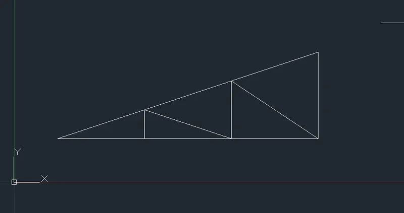
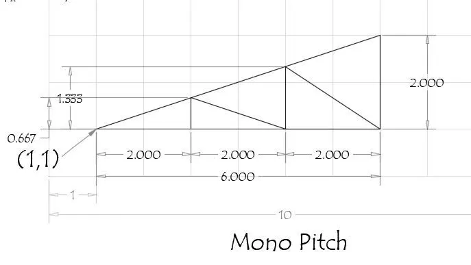
3. Drafting the Mono Pitch as shown in the given picture by using Absolute Coordinate System :
STEPS :
- Select the line tool from the ribon tab.
- Specify the starting co-ordinate of point 1 as 1,1
- Specify the next co-ordinate of point 2 as 7,1
- Specify the next co-ordinate of point 3 as 7,3
- Click 'Esc' to cancel the Line Command
- Select the line tool from the ribon tab.
- Specify the next co-ordinate of point 4 as 3,1
- Specify the next co-ordinate of point 5 as 3,1.667
- Specify the next co-ordinate of point 6 as 5,1
- Specify the next co-ordinate of point 7 as 5,2.333
- Specify the next co-ordinate of point 8 as 7,1
- Click 'Esc' to cancel the Line Command
Result :