Creating a Floor plan, Footing detail and Isometric view using AutoCad
AIM :
To create a floor plan, footing detail and isometric view using AutoCAD.
INTRODUCTION :
Autocad software consists of different tools that are essentially for drafting a floor plan, footing detail or an isometric view. Some of them includes rectangle, polygon, polyline. There are various modification tools in AutoCad which are used to modify the sketched objects and these includes move, copy, offsetting, rotating, Scaling of sketched objects, filleting, chamfering etc.
PROCEDURE :
1. C1 Cross section of load bearing wall over spread footing.
- Rec in command line and press enter
- Specify first corner of the rectangle
- Specify next point as 0.90, 0.25
- Select line from the ribbon
- Specify next point as @0.20, 0
- Specify next point as @0, 0.40
- Specify next point as @0.05, 0
- Specify next point as @0, 0.40
- Specify next point as @0.05, 0
- Specify next point as @0, 0.60
- Specify next point as @0.30, 0
- Specify next point as @0, -0.60
- Specify next point as @0.05, 0
- Specify next point as @0, -0.40
- Specify next point as @0.05, 0
- Specify next point @0, -0.40
- Press Esc and then reselect line tool from ribbon
- Specify the start point b
- Specify next point @0, 0.05
- Specify next point @0.30, 0
- Specify next point @0, -0.05
- Press Esc and then reselect line tool from ribbon
- Specify the start point c
- Specify the next point @0, 1
- Specify next point @0.30, 0
- Specify next point @0, -1
- Press Esc and then reselect line tool from ribbon
- Specify start point d
- Specify next point @-0.30, 0
- Specify next point @-0.05, 0
- Specify next point @-1.15, 0
- Specify next point @0, -0.15
- Specify next point @1.15, 0
- Press Esc and then reselect line tool from ribbon
- Specify start point e
- Specify next point @0.30, 0
- Specify next point @0, 0.15
- Specify next point @0.30, 0
- Specify next point @0, 0.15
- Specify next point @0.30, 0
- Specify next point @0, 0.15
- Specify next point @0.30, 0
- Press Esc and then reselect line tool from ribbon
- Specify start point f
- Specify next point @1, 0
- Specify next point @0, -0.60
- Specify next point @-0.95, 0
Result :

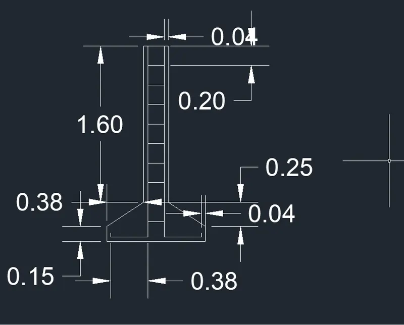
2. C2 Cross section of isolated footing
- Draw line with command LINE and give 1 unit length
- Specify relative coordinates @0, 0.15
- Specify next coordinate @0.38, 0.25
- Specify next coordinate @0, 1.6
- Specify next coordinate @0.24, 0
- Specify next coordinate @0, -1.6
- Specify next coordinate @0.38, -0.25
- Specify next coordinate @0, -0.15 or select Close
- Draw a line at a distance of 0.04 units from the top with line command
- Give value 0.04,then give the length of first line as 1.96
- Specify coordinate for second line @-0.38, 0
- Specify third line coordinate @0, 0.06
- Copy first line by command COPYand give value of 0.16 units
- Copy the second horizontal line by COPY command and specify base point and drag to desired position
- Copy the third horizontal line and select the base point and drag it
- Give offset from top line with an offset distance of 0.2 units
- Give command OFFSET and select the object giving offset distance as 0.2 and select multiple option for 9 such lines.
Result :
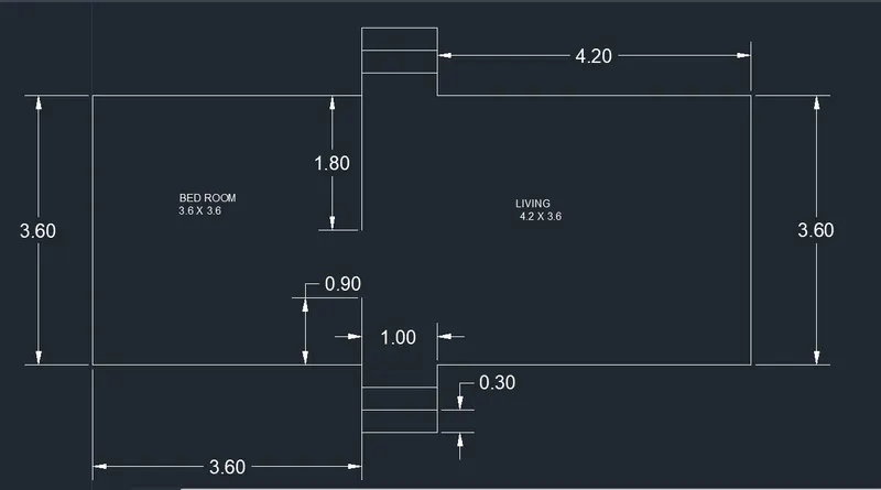
3. C3 Line diagram of a two bedroom building.
- Select polyline from ribbon and create bedroom of 3.6*3.6
- Command POLY and click a point then move the cursor towards south and give 0.9 units
- Move to north and give distance of 3.6 units and then move to east and give 3.6 units and finally to south with 1.8 units
- The step outline is created using LINE tool
- Now from the corner point of 1.8 units draw a vertical line at a distance of 0.9 units
- Move the cursor to east and give distance of 1 unit
- Move to south with 0.9 unit
- Now draw living room is drawing using polyline also
- Give command POLY from the last point and then start the polyline
- Give 4.2 units in east
- Now move to south and go 3.6 units
- Move to west and go 3.6 units
- Create outline step again
- Specify command LINE select the last point drawn
- Move to south and go 0.9 units
- Move to west and go 1 units
- Move to north and go 0.9 units
- Create the steps using offset with using command OFFSET and give 0.3 units distance by selecting object
- Click on multiple and move the cursor to the direction where it is to be drawn.
Result :
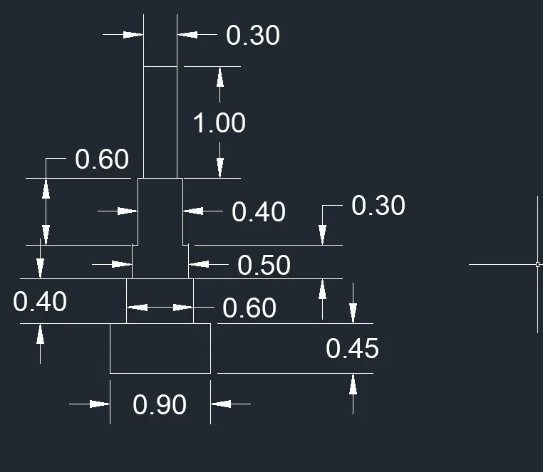
4. C4 Cross section of load bearing wall showing foundation details.
- Draw a rectangle using command REC, choose first corner point and then specify the other corner point as @0.9, 0.45.
- Choose the line tool to a draw a centre line for the second footing from the centre of the top edge of the rectangle drawn, the other point of the line is provided as @0, 0.4.
- This line is the offsetted at distance of 0.3 on either side and then the centre line is erased off. Then the top point of the two line are joined temporarily.
- Following the above procedure third and fourth footing is created.
- Trim off the protion between the top edges of 2nd and 3rd footing.
- Now the wall portion is also drawn by first drawing the center line from the midpoint of the fourth footing i.e first pont willl be the midpoint and the second point is @0,1.
- This center line is then offsetted on either side at an offset distance of 0.15 on either side and then the center line is erased off. After that the top points are then connected using line command to complete to figure.
- Finally complete the figure by dimensioning it.
Result :
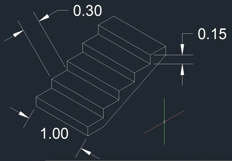
5. C5 Isometric view of steps.
- First type DS command, this will lead to dialogue box named drafting settings in that choose the snap and grid option change the snap type to isometric snap.
- Then choose the line command and specify the first point.
- Then by distance entry method input the distance one by one and complete the drawing in the isometric plane.
- Now again choose line option and change to isoplane top by pressing the key F5 and then continue entering the distance values.
- Now again change to Isoplane left to continue drawing.
- Similarly continue drwaing by switching between isoplane left and isoplane top.
- Now, this drawing is closed by using line tool connecting between two ends.
- Complete the figure by dimensioning it.
Result :
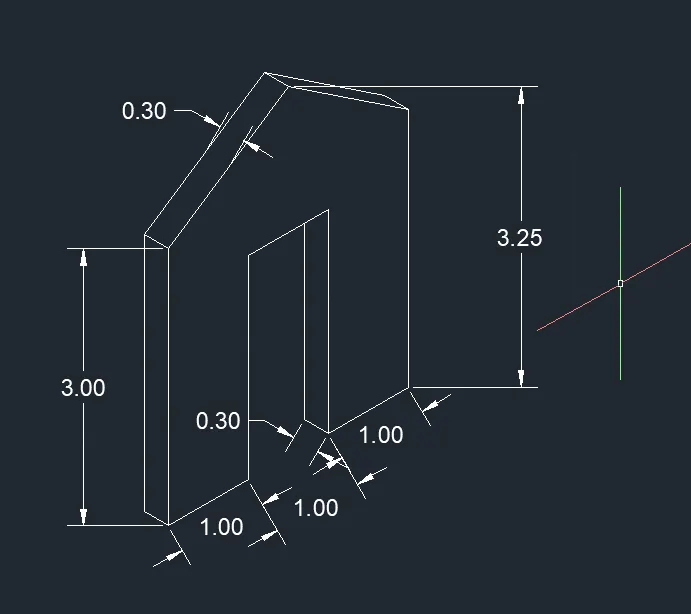
6. C6 Isometric view of Gable wall.
- First type DS command, this will lead to dialogue box named drafting settings in that choose the snap and grid option change the snap type to isometric snap.
- Then choose the line command and specify the first point.
- Then by distance entry method input the distance one by one and complete the drawing in the isometric plane.
- First chose isoplane right and enter 3 and then press F5 and change to isoplane left and enter 0.3 and change direction to down and enter 3.
- Now change to isoplane top and enter 1, then change to isoplane right and enter 2.42 and then towards right enter 1 and downwards enter 2.42.
- Then towards right enter 1 and upwards enter 3 and change to isoplane left and enter 0.3.
- Now draw a centerline from midpoint of door portion in isoplane right to height of 0.83 and from that top point join both sides of wall slantingly after this erase off the center line.
- Complete the figure by dimensioning it.
Result :