Week 1 Challenge
1
1) The steps involved to upload a .std file through web mail :-
Goto your mail then compose mail to upload your file click attach in .std formate finally browse the file.
2) Name the different materials that can be designed using STAAD Pro :-
a) Concrete
b) Steel
c) Aluminium
d) Timber
e) Composite
f) Sections
3. Is it possible to capture images in STAAD Pro :-
Yes, Take picture command
4. Name the three ways by which you can create a model :-
a) Analytical
b) Physical
c) Building
5. Steps followed to assign properties in a model :-
* In the STAAD PRO software, Goto PROPERTIES tab.
* In the PROPERTIES tab select concrete then click on Define then select shape enter dimensions in x and y.
* In the PROPERTIES tab select steel then click on section database then select indian then choose section.
2)
1) Name any six design parameter involved in RCC design :-
Ultimate tensile strength of steel - Fu
Yield strength of steel - Fy
Effective length factor - Kx,Ky,Kz
Length for torsional buckling - Lx,Ly,Lz
Allowable L/R in compression - MAIN
Max allowable loacal deflection - DFF
2) The different cursor types available in STAAD Pro :-
Node cursor
Beam cursor
Plate cursor
Solid cursor
3) Generate different views for a model :-
* In the STAAD PRO software Goto Views tab select different views front top side views.
4) Procedure to define a “Simply Supported” condition in STAAD Pro :-
* Select Supports and assign pinnied support or fixed but and release degrees of freedom.
5) Name any five topics that you will include while creating DBR :-
DBR - Design Basic Report
* Introduction of project
* Structural layout
* Load and load combination
* Analysis and Design methodology
* Quality assurance plan
6) The term “Multi material design” of STAAD Pro :-
* Steel
* Concrete
* Aluminium
* Timber
* Composite structures
3)
1) The structure systems in STAAD Pro :-
* Space
* Plane
* Frame
* Truss
2) Explanation of the coordinate system adopted in STAAD Pro software :-
There are two type
a) Global coordinate system
b) Local coordinate system
a) Global coordinate system
The global coordinate system is an arbitary coordinate system in space which is utilized to specify the overall geometry and loading pattern of the structure.
Global coordinate system are different types they are
Conventional cartesian coordinate system :-
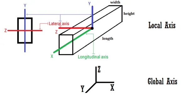
This coordinate system is a rectangular coordinate system(X,Y,Z) which follows the orthogonal right hand rule. This coordinate system may be used to define the joint locations and loading directions.
Cylindrical coordinate system :-
In this coordinate system, the X and Y coordinates of the conventional cartesian system are replaced by radius(R) and angle in degrees. The Z coordinate of the cartesian system and its positive direction is determined by the right hand rule.
Reverse cylindrical coordinate system :-
This is a cylindrical type coordinate system where the radius-angle plane corresponds to the X-Z plane of the cartesian system. The right hand rule is followed to determine the positive direction of the Y axix.
b) Local coordinate system :-
A local coordinate system is associated with each member and is utilized in MEMBER END FORCE output or local load specification.
Each axis of the loacal orthogonal coordinate system is also based on the right hand rule. Note that the local coordinate system is always rectangular.
A wide range of cross-sectional shapes maybe specified for analysis. These include rolled steel shapes, user specified prismatic shapes ect...
3) Elaborate DBR and its uses :-
DBR - Design Basic Report
* To specify and compile the data required for analysis and design of structural elements of the project.
* It clearly depicts the assumptions and specifications that are being used to develop the construction documents for a project.
* It will also help avoid the "scope creep" that can detail the project schedule and lead to budget overruns.
* It basically transforms the WHAT into the HOW.
4) The different types of analysis options in STAAD pro :-
* Perform analysis
* P delta analysis
* Push over analysis
* Non Linear Analysis
* Buckling Analysis
5) The difference between Fixed and Fixed But condition :-
When the FIXED or FIXED BUT type of support is specified, for those degrees of freedom which are to be treated as fully restrained, STAAD assumes the displacements to be known quantities whose value is zero.Hence, those degrees of freedom are not considered for the stiffness matrix, and their value is not calculated.(For the FIXED BUT support type, if any degees of freedom are assigned a spring using the KFX and KMZ terms, those are treated as unknowns and their displacements are calculated).
Aim :-
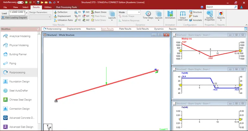
Create a STAAD Model with the following Specification
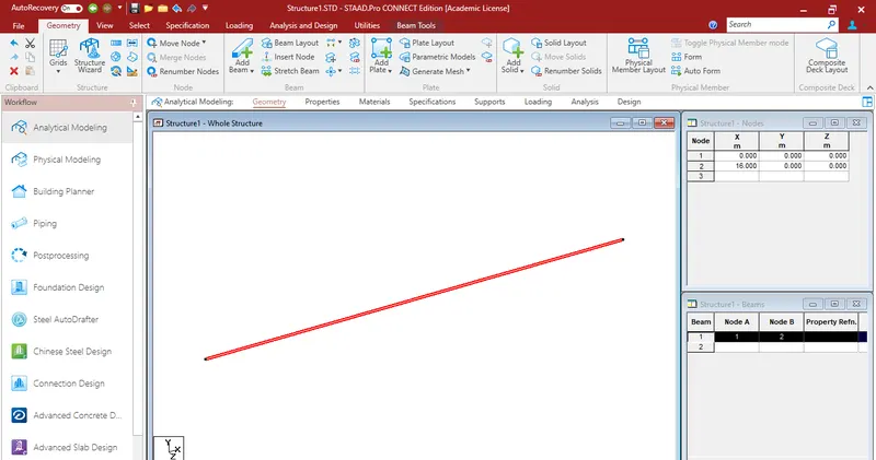
a. A beam of span 16m
b. Support : Fixed on one end and Roller support(Horizontal) on the other end
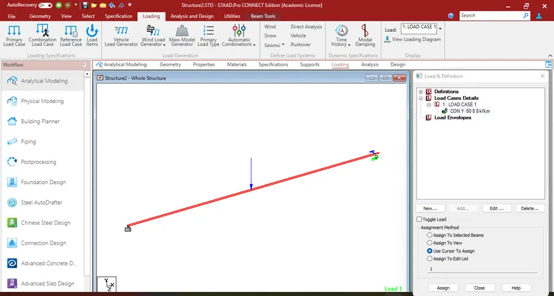
c. A point load of 50 kN at the mid-point
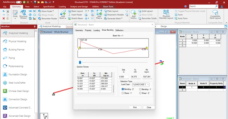
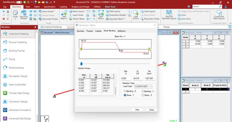
d. Draw SFD and BMD using software
Procedure :-
* Open the staad software.
* Units set as m and load as kN.
* In the top dorp down on grids tab, click on beam grid.
* Draw the beam.
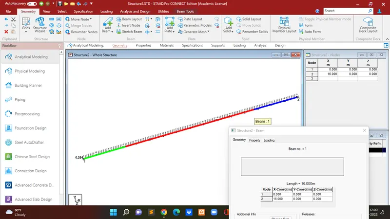
* Goto properties tab, dialog box select define provide the size of beam.
* Goto material tab to assign material.
* Goto support tab,click on create then select the supports.
* Finally goto loading tab, dialog box load cases details add load case then edit the load then assign.
* Finally click on the beam dialog box will be appear select shear bending display the shear and bending moment diagrams.
Result :-
Successfully create a STAAD Model with the following Specification
a. A beam of span 16m
b. Support : Fixed on one end and Roller support(Horizontal) on the other end
c. A point load of 50 kN at the mid-point
d. Draw SFD and BMD using software