Week 1 Challenge
1. 1. Write the steps involved to upload a .std file through web mail?
2. Name the different materials that can be designed using STAAD Pro.
3. Is it possible to capture images in STAAD Pro? If yes how?
4. Name the three ways by which you can create a model.
5. Write the steps followed to assign properties in a model.
2. 1. Name any six design parameter involved in RCC design.
2. What are the different cursor types available in STAAD Pro?
3. How will you generate different views for a model? State the steps involved.
4. Explain the procedure to define a “Simply Supported” condition in STAAD Pro
5. Name any five topics that you will include while creating DBR.
6. Describe the term “Multi material design” of STAAD Pro.
3. 1. Name the structure systems in STAAD Pro? Explain each system?
2. Explain the coordinate system adopted in STAAD Pro software.
3. Elaborate DBR and its uses.
4. Explain the different types of analysis options in STAAD pro.
5. Explain the difference between Fixed and Fixed But condition.
Practical
1. Create a STAAD Model with the following Specification
a. A beam of span 16m
b. Support : Fixed on one end and Roller support(Horizontal) on the other end
c. A point load of 50 kN at the mid-point
d. Draw SFD and BMD using software
ANSWERS ;
1.1
- Select back import from back stage, The import from STAAD.pro dialog opens
- Click general settings to browse and select a STAAD pro (*.std) file to import
- Select use mapping file in the settings and then click to browse the select a mapping file to import
- Set the catalog type and catalog instance assignment for the imported member types, the data is used by AECO sim building to rebuild the members structural data as define in the structural member catalog
- In steel section , select a section definition that is designated as the default section name , This section definition is applied to imported menbers whose section data is not available in AECO sim Building designer
- Check verify to scan the imported file for unknown sections
- The unknown section dialogue box appears providing the oppertunity to write unknown sections to the active XML section definition file before importing,
- In revision tracking check Use design history tracks changes to a DGN file , Viewing details about the revision by using the controls on its tool
- Click import , The update design dialog appears , Review detailed imformation about each imported member and select which one you want to import before accepting them in to the target DGn file.
- Click update to complete the import process
- The structure is updated.
1.2
- To create a isotropic material definition for use with your model by the following procedure,
- Set the input units before creating a new material definition
- It includes a set of predefined materials for concrete, aluminium steel and stainless steel
- Select material page>Analytical Modelling
- In the material > whole structure dialog isotropic tab > click create,
- Type a tittle to identify the material,
- Type the values of the material properties used for analysis
- Select type of material from the dropdown list
- Type the strength values in thedesign properties, the field corresponding to the selected material type are active
- click ok
1.3
- Yes , it is possible to capture images in STAAD pro.
- Plot the appropriate diagram and take a picture of it by clicking the Take Picture icon as shown in the screenshot below. Take pictures of as many items you need to and each time you will be prompted to provide a caption for the picture
1.4
-
there are three methods of creating the structure data:
All three methods of creating the model are explained in this tutorial. The physical modeling method is explained first, beginning with " T.3 Creating the Model using the Physical Modeler," then the analytical model method is explained beginning with " T.3 Description of the tutorial problem ." The command file method is explained in " T.3 Creating the model using the command file ."
1.5
| STAAD.Pro Physical Modeler | Analytical STAAD.Pro Modeling User Interface |
|---|---|
| 1. Select the members which all have the same section. | 1. Add the profile you want to use from the Section Database. |
| 2. Select the Section tool in the Assign properties group on the Member ribbon tab. | 2. Select the member property in the Properties dialog. |
| 3. Select the profile to use and click OK. | 3. Use the cursor to click on members with this property. |
In STAAD.Pro Physical Modeler, the general order of operations is that you first select physical objects and then assign properties or perform some operation on the selection.
This differs from STAAD.Pro, where there are many tasks in which you select the operation, property, or specification first and then assign that to some list of model objects.
2.1
-
The following steps to be considered for the analysis and designing of RCC building by using STAAD Pro software
- Modelling of building.
- Applying the load cases
- Analysis of building
- Designing of building
- Checking the results for reinforcement details
- Foundation design by STAAD Pro
2.2
- Tool nameDescription

Nodes CursorUsed to graphically select nodes.
Beam CursorUsed to graphically select beams.
Plate CursorUsed to graphically select plates.
Solid CursorUsed to graphically select solids.
Geometry CursorUsed to graphically select nodes, members and elements of the structure simultaneously.To select nodes, members, or elements using the Geometry Cursor, simply click on the desired structural components. To select multiple nodes, members and elements, hold while selecting. We may also select the structural components graphically by creating a window on screen with the cursor around these components.

Members CursorUsed in Steel Design or Concrete Design to graphically select all those beams defined as a same member in the member set up of member design, simultaneously.Members may be user defined or may be generated automatically using the Auto Form Member tool.
To select all the beams defined as a same member using the Member Cursor, just click on one beam. The other beams having the same member name as the selected one will automatically be selected. To select multiple physical members, hold down while selecting. You may also select the physical members graphically by dragging a fence area around these physical members using the cursor.

Plates & Solids CursorUsed to graphically select both plate and solid elements.
(Select) TextUsed to add comments and titles to pictures and result diagrams. The added text can be plotted, too.The inserted text can be deleted, moved, and modified using the text cursor. Refer to the Insert Text on the Utilities ribbon for a detailed description on inserting text and modifying it using the text cursor.

PreviousSelects the last objects selected if they have been deselected or if the selection set has changed.
LoadUsed to modify any load already applied on the model by double clicking it. When selected, the mouse pointer changes to the Load Edit Cursor.
2.3
- GOTO Views - Select different views from top side views etc.,
2.4
- A simply supported beam is one that rests on two supports and is free to move horizontally. Typical practical applications of simply supported beams with point loadings include bridges, beams in buildings, and beds of machine tools.
- Exp No: Date: DESIGN OF SIMPLE BEAM USING STAAD.PRO AIM To design a simple beam using STAAD.Pro SOFTWARE USED STAAD.Pro PROCEDURE: 1) STARTING THE PROGRAM 1. ...
- Select support 2 Assign to view Assign (Click 'Yes' when prompted to proceed) 5) SPECIFY MEMBER LOADS 8.
2.5
- INTRODUCTION OF PROJECT
- STRUCTURAL LAYOUT
- LOAD &LOAD COMBINATION
- ANALYSIS AND DESIGN METHODOLOGY
- QUALITY ASSURANCE PLAN
2.6
- STEEL
- CONCRETE
- ALUMINIUM
- TIMBER
- COMPOSITE STRUCTURE
3.1
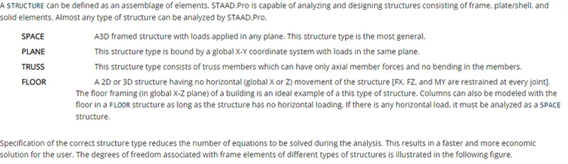
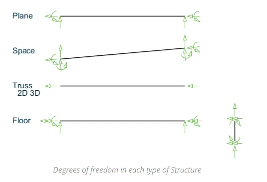
3.2
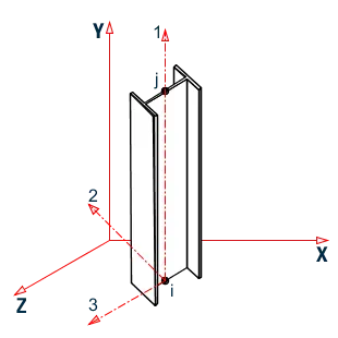
- STAAD.Pro Physical Modeler uses a conventional Cartesian coordinate system, with the global Y axis assumed as vertical (i.e., "Y up", or the height of the structure is parallel to the global Y axis).
Global Coordinate System
This coordinate system is a rectangular coordinate system (X, Y, Z) which follows the orthogonal "right hand" rule. This coordinate system may be used to define the joint locations and loading directions. The translational degrees of freedom are denoted by u1, u2, & u3 and the rotational degrees of freedom are denoted by u4, u5, & u6.
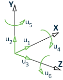
Degrees of freedom as used in STAAD.Pro
Local Coordinates
Each member or surface has its own local Cartesian coordinate system which is also oriented using the "right hand" rule.
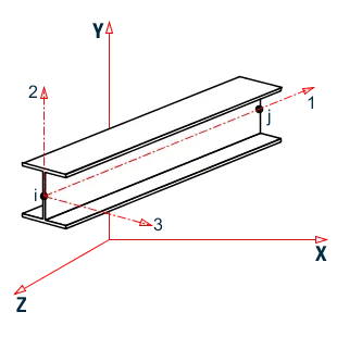
The longitudinal axis of a member is the first axis, with the positive axis taken from the i to the j ends (i.e, Ni and Nj). The second axis is the oriented such that the 1-2 plane is then parallel to the global Y axis. The third axis is then normal to the first and second local axes as defined by the right hand rule. The local 2 and 3 axes coincide with the two principle moments of inertia of the cross-section. In the special case of a vertical member (where the local 1 axis is parallel to the global Y axis; i.e., a column), the local 3 axis is then made parallel to the global Z axis and the 2 axis is oriented respectively.
 |
 |
| (A) |
(B |
For surfaces, the local x axis is aligned with the edge defined by the first two nodes of the surface (i.e., N1 and N2). The program then calculates the area of each triangle formed by any other nodes to determine the largest area. This triangle determines the plane of the surface and the local y axis lies perpendicular to the x axis within this plane. The third axis is then orthogonal to the surface as defined by the "right hand" rule.
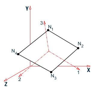
Local coordinates of a surface
3.3
-
DBR scheduling will deliver a number of returns to your shop, but the biggest advantages that it can offer are:
- Decreased lead time
- Increased throughput
- Better communication and priority management
3.4
-
STAAD building planner
STAAD provides a visualization module of the building planner which generates models of the building that can be designed and analyzed in the software program. This software is interactive and intuitive which makes it easy the work on making changes in the geometry specification operations with fewer mouse clicks in the workflow.
Physical modeling
Physical modeling is one of the most significant features used in the software. It is a simplified physical modeling process of a structure. This software Visualize Beams, columns, and surfaces placed in the model corresponding to which they appear in the physical world spanning multiple floors and a surface representing an entire floor of a building.The visualization of generated joint where two physical objects meet in the model.
Analytical Modelling
An analytical model can be created employing the ribbon-based user interface by making changes and editing the command file which is of types like Dxf, and cis/2.The model geometry can even be generated from the data of macro-enabled applications (Like Microsoft Excel, Micro stations, etc) by using Macros.
Steel AutoDrafter
Steel AutoDrafter produces an excellent workflow plan that extracts planar drawings at any level and sections in any of the orthogonal materials from the structural steel model prepared in STAAD.Pro.
Advanced Slab Design
The STAAD. Pro Advanced Slab Design works within the STAAD. Pro-environment is an integrated software design tool workflow. In this software concrete slabs can be defined and the data can be passed to RAM Concept which includes all the design requirements of structural and civil design consisting of the geometry, material, loads, and analysis.
Advanced concrete Design
The advanced concrete design workflow software application powered by the RCDC application provides direct access for STAAD.Pro models. This software application is standalone requiring a model and result data from a suitable analysis, operating outside the STAAD.Pro software environment. The model is made up of beams and columns as plates are not currently supported. RCDC software application can be utilized to design the objects such as Pile caps, Footings, columns and walls, beams, and slabs. This software works within the projects as each design created in RCDC is retained and displayed when RCDC is re-entered balancing the previous design which can be recalled and continued. The BBS of perfect quality can be generated as required and can be executed instantly.
STAAD.Beava
This design software is used in the design of bridges, consisting of loading rules and constraints, The entire process of load application is complex, as rules can impose parameters, such as loaded length on lane factors, lane, and intensity of the load.
In order to obtain the maximum best design effects, engineers try working on many loading situations that lead to the generation of many live load application instances as large output data which must be combined with the dead load and other effects. Talking about this software application we have a Bridge deck that is used to minimize the load of the application process in adherence to the national code requirements. This software application program was generated by STAAD.Pro in the loading process which is based on the use of influence surfaces.
An influence surface is a three-dimensional form and 2 D influence function for a single member. STAAD.Pro generates influence surface automatically which is completely based on the building structural effects such as the bending moments for elements, and the corresponding deflection in all the degrees of freedom nodes and support reactions. In order to obtain maximum desired results, the end-user can instruct the program by employing relevant influence surfaces thus optimizing load positions in compliance with the code requirements.
Earthquake mode
In this design software, the requirement and specifications work in accordance with building structures in seismic zones and regions. These requirements ensure that the structures can sustain seismic loads and remain stable in the seismic events. The STAAD.Pro software workflow is used to check if the structure conforms to the basic geometric recommendations.
The civil engineering department of the JBIT Group of institutions organized a 5-day training program on STAAD Pro with TEQIP III which is a structural analysis and design software that can be used to design RCC.
3.5
-
1) Even though the two types follow different approaches, the end result - joint displacements, member forces and support reactions - should be the same.
2) Since the number of unknowns is less in the former method compared to the latter, the time required to compute the results will also be comparatively less using the first method. If the model is large, there may be a significant reduction in time required to perform the analysis.
3) For supports directly attached to plates or solids, if the supports are subjected to artificial displacements (called sinking support or support settlements), the effects caused by such displacements can be computed only if the ENFORCED type of support is used. In STAAD, support displacement loads cannot be applied to such models when the FIXED type of support is specified.
4) For the ENFORCED BUT type, there is no provision to specify a spring constant. The only choices, which are built into the program, are - zero stiffness or very high stiffness. So, if a user plans to assign his/her own spring constant, the FIXED BUT type is the only choice.
5) If the engineer plans to analyze a model in which support conditions change depending on the loading condition (hence he/she specifies the support command multiple times in the model), there are a few restrictions on how the supports must be assigned. These are mentioned in Section 5.38 of the Technical Reference manual where the CHANGE command is described. The ENFORCED support may offer a way to overcome some of those restrictions.
- Practical
1. Create a STAAD Model with the following Specification
a. A beam of span 16m
b. Support : Fixed on one end and Roller support(Horizontal) on the other end
c. A point load of 50 kN at the mid-point
d. Draw SFD and BMD using software
AIM :
To create a given STAAD pro model followinmg given procedure
PROCEDURE :
- STAAD file is attached.
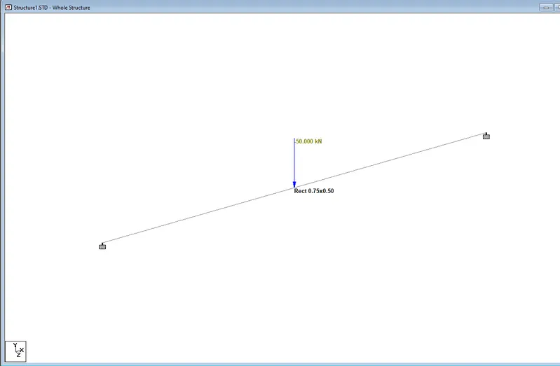
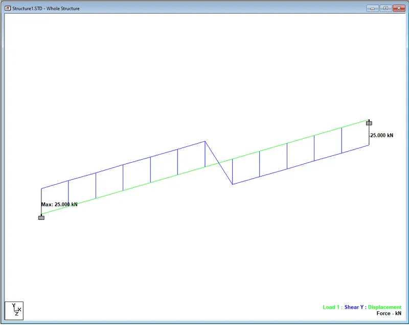
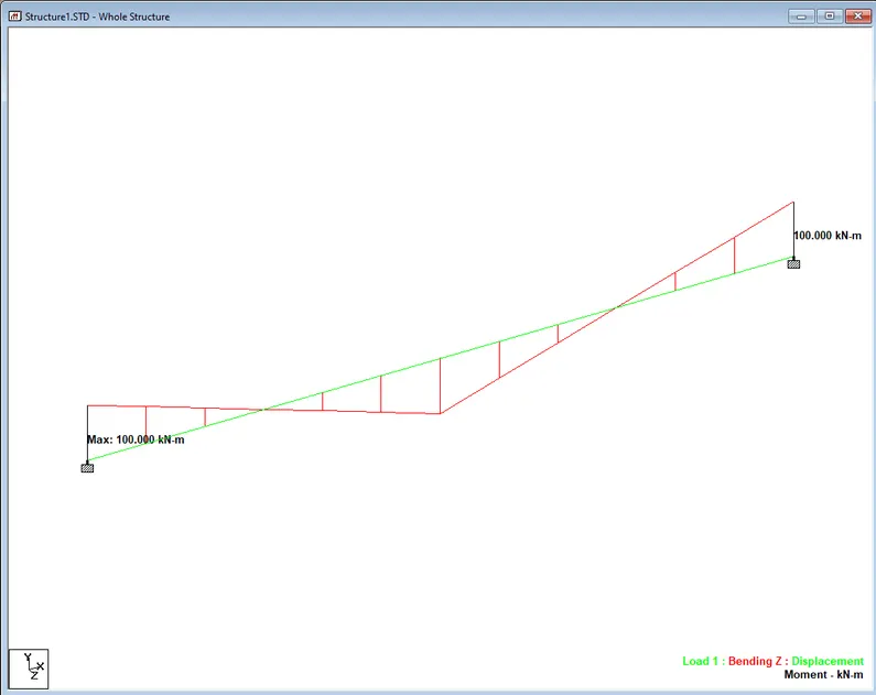
RESULT :
Created a STAAD model with the given following specifications.