ANSA_PROJECT 3 - COMPLETE MESHING AND CONNECTION FOR CROSS CAR BEAM (CCB) ASSEMBLY
Objective:
Perform CAD model check, implement meshing according to the required quality criteria and provide required connections to the model.
|
S.No |
Quality Criteria |
Value |
|
1 |
Target/Average length |
5 |
|
2 |
Minimum Length |
3 |
|
3 |
Maximum Length |
7 |
|
4 |
Aspect |
3 |
|
5 |
Warpage |
15 |
|
6 |
Skewness |
45 |
|
7 |
Jacobian |
0.7 |
|
8 |
Minimum Quad Angle |
45 |
|
9 |
Maximum Quad Angle |
135 |
|
10 |
Minimum Tria Angle |
30 |
|
11 |
Maximum Tria Angle |
120 |
|
10 |
Tria Percentage |
15 |
Procedure:
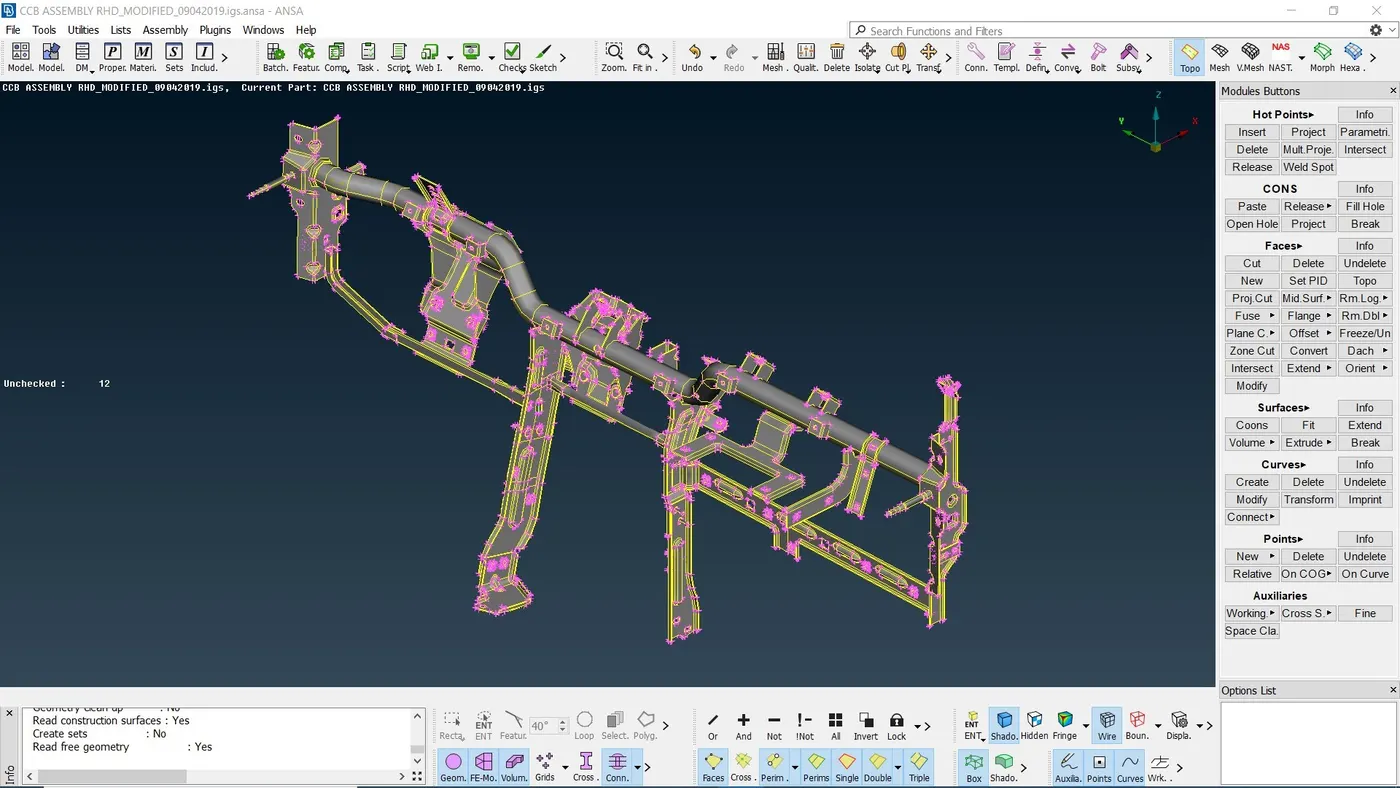
1. Import the CAD model of a CCB assembly into ANSA interface.
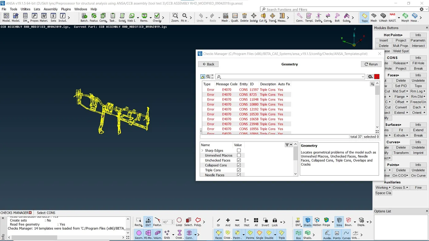
2. Perform an initial geometry check and fix the errors if any.
3. Visually check the orientation and rectify if any discrepancies arise.
4. Mid surfacing has to be achieved manually. Using offset command, mid surface is generated. The mid surface generated is isolated and saved as a new PID.
Topology is performed on each component individually.
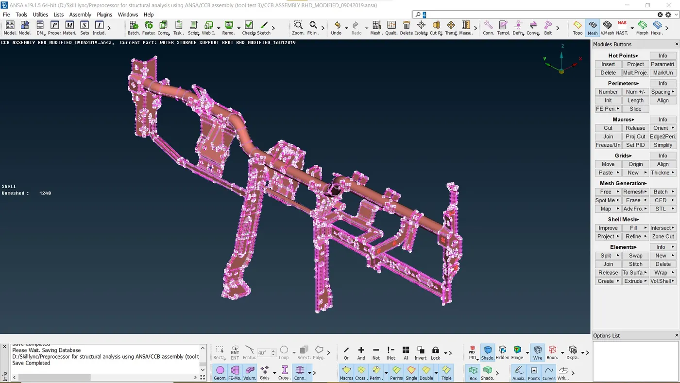
After generating mid surface for each component, another geometry check is conducted.
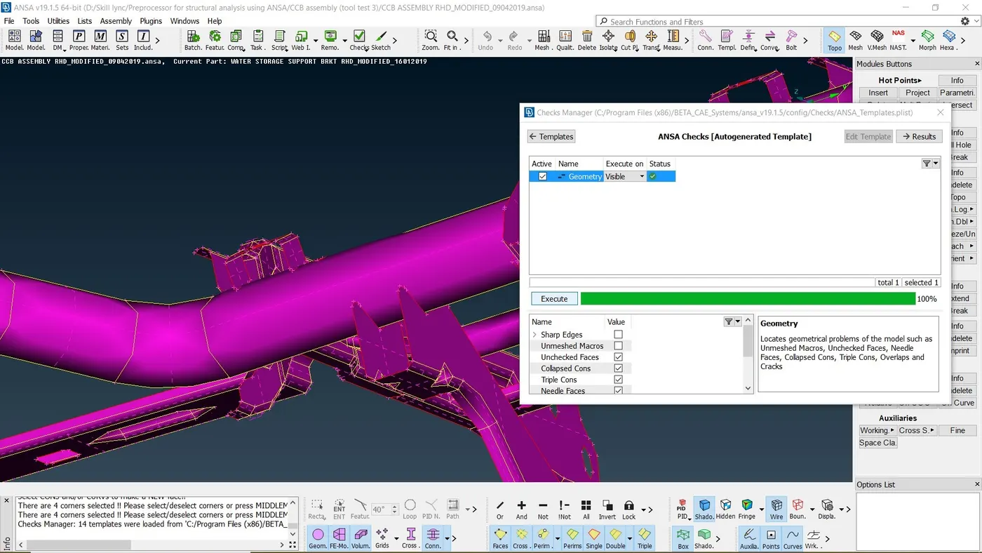
5. In the mesh interface, quality criteria and mesh attributes are assigned as required. Best command is used to generate mesh. Quality check is performed on the generated mesh. Mesh is adjusted accordingly such that it obeys the required quality criteria.
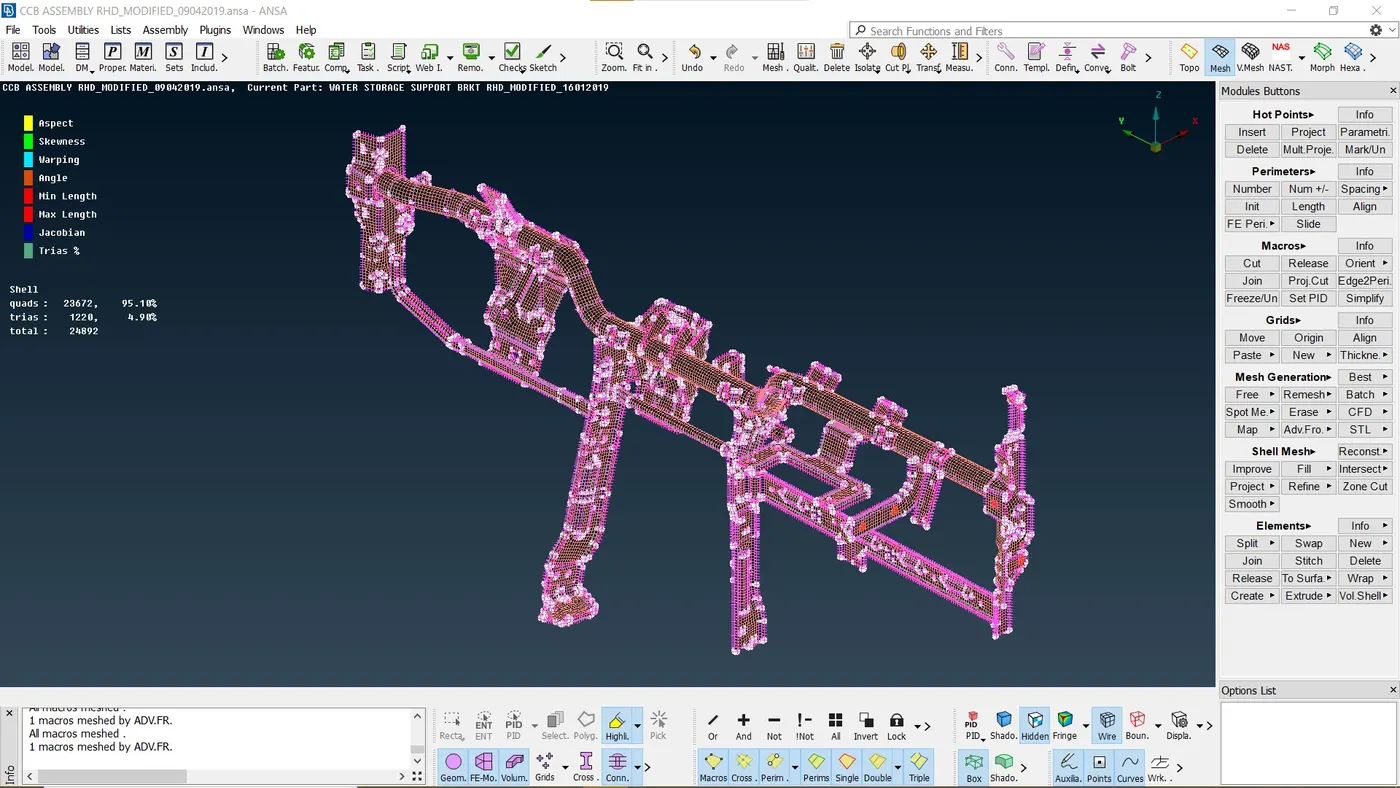
Mesh cleanup is done using the combination of following commands as and when required:
1. Reconstruct
2. Delete nodes
3. Cut
4. Smooth
5. Split
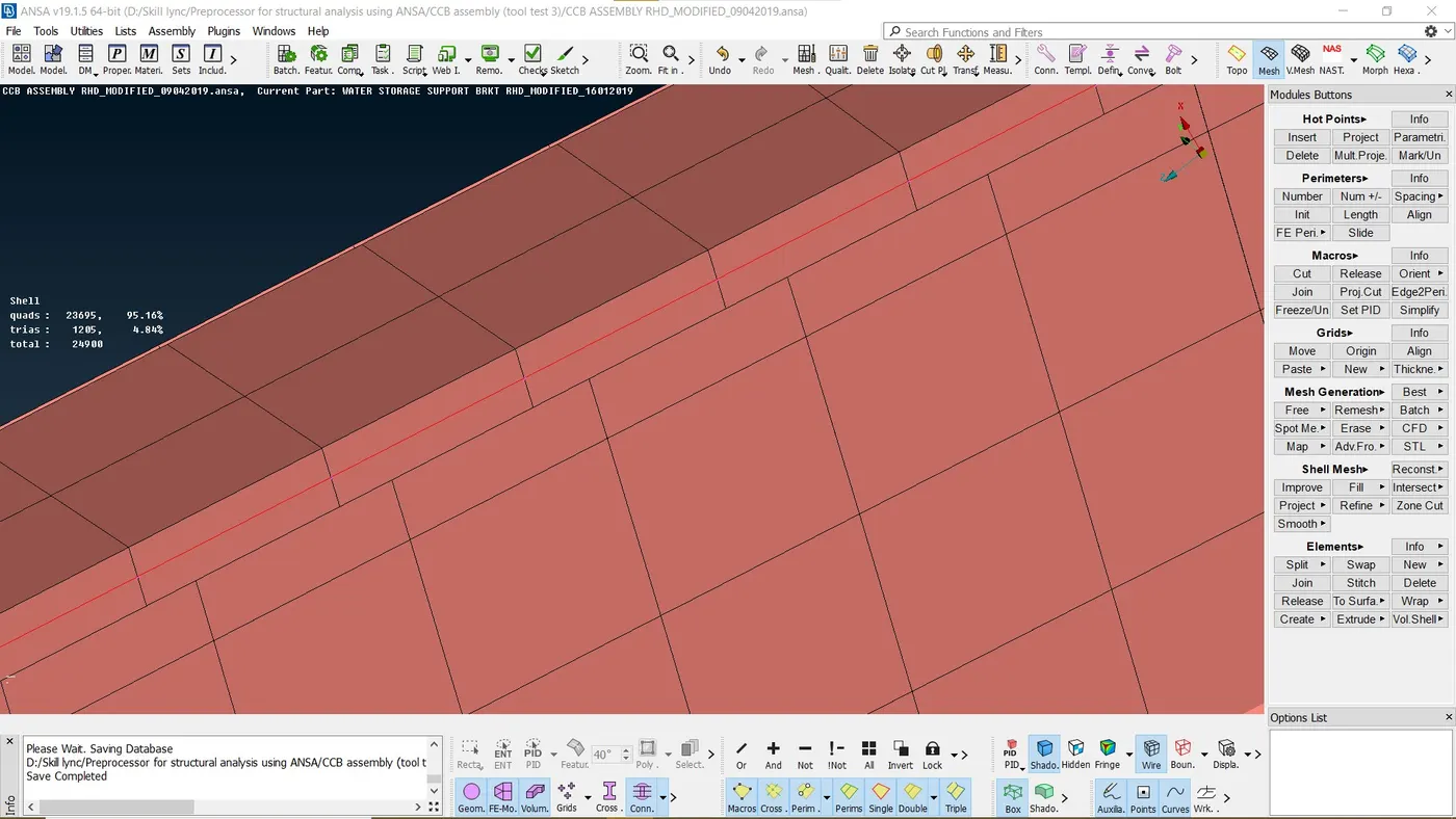
6. After successful meshing, thickness of 1.2mm is assigned. In the presentation parameters, "draw shell as a solid" feature is switched on.
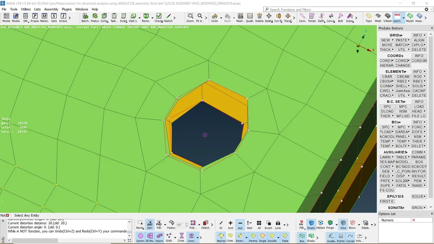
7. We will begin adding connections by assigning bolts to the necessary holes. A 3D point is created at COG of the hole. A zone cut is applied at the perimeter of the bolts in order to acheive quad elements at the first row. Using the first row of nodes for a RBE2 connection will imply the condition of washer being used in the nut bolt scenario.
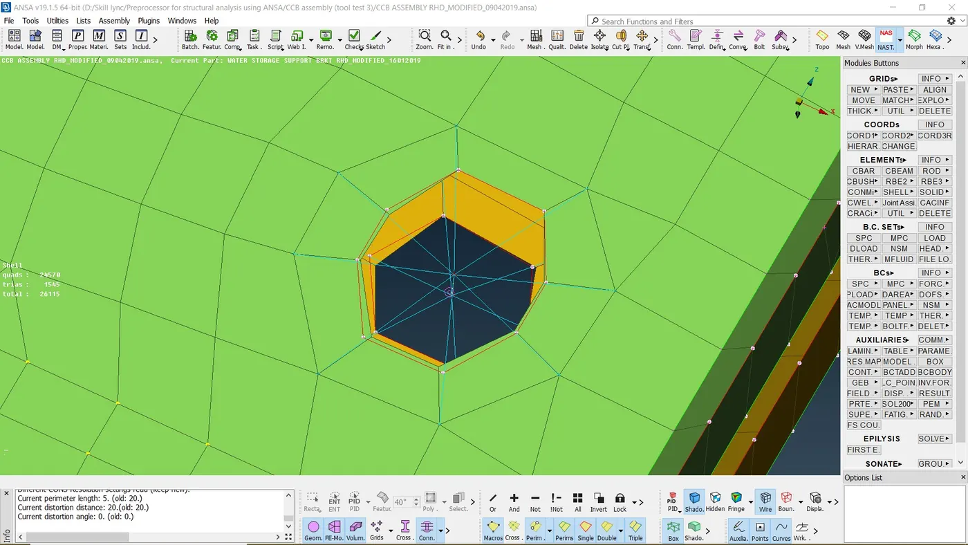
8. It is converted in to a bolt using the connections manager. In the connections manager, the required data such as assigning planes, search distance and type of zones are added in to the model.
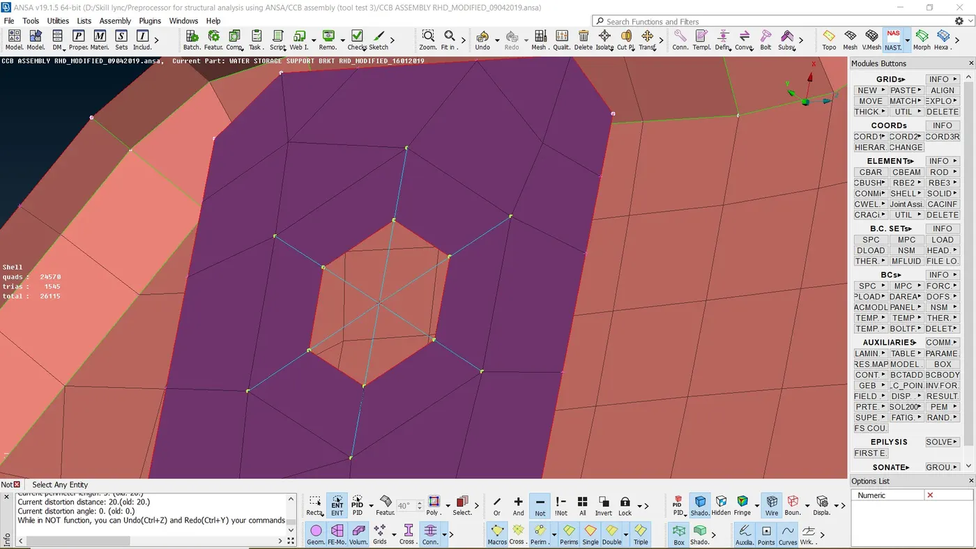
9. Some parts of the CCB assembly are connected using cluster RBE2 connections at he ends and spotwelds at other locations.
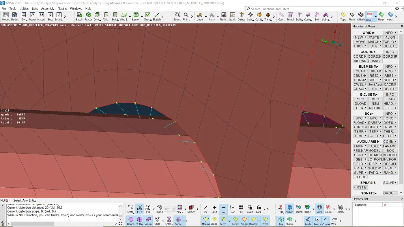
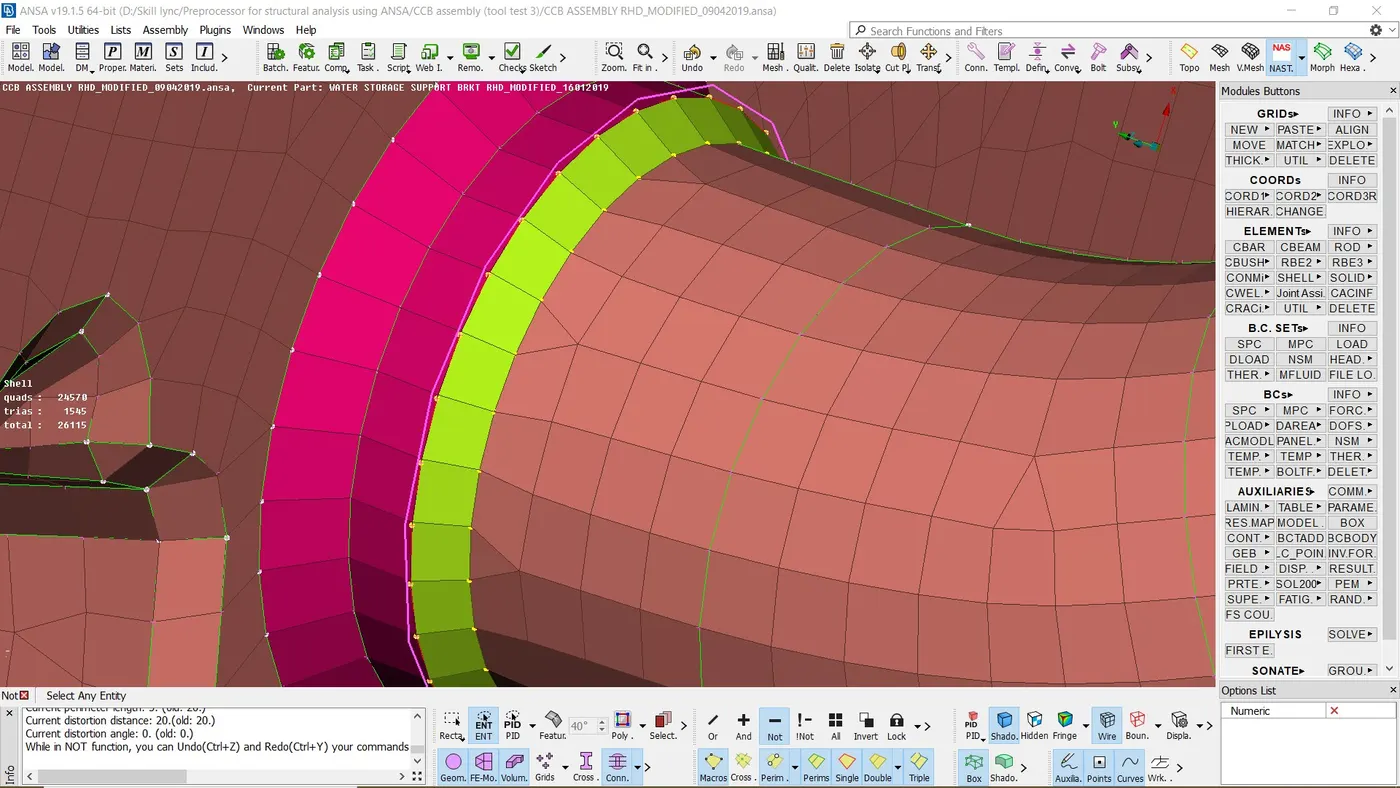
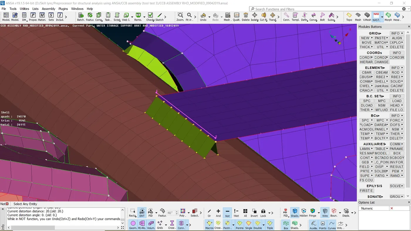
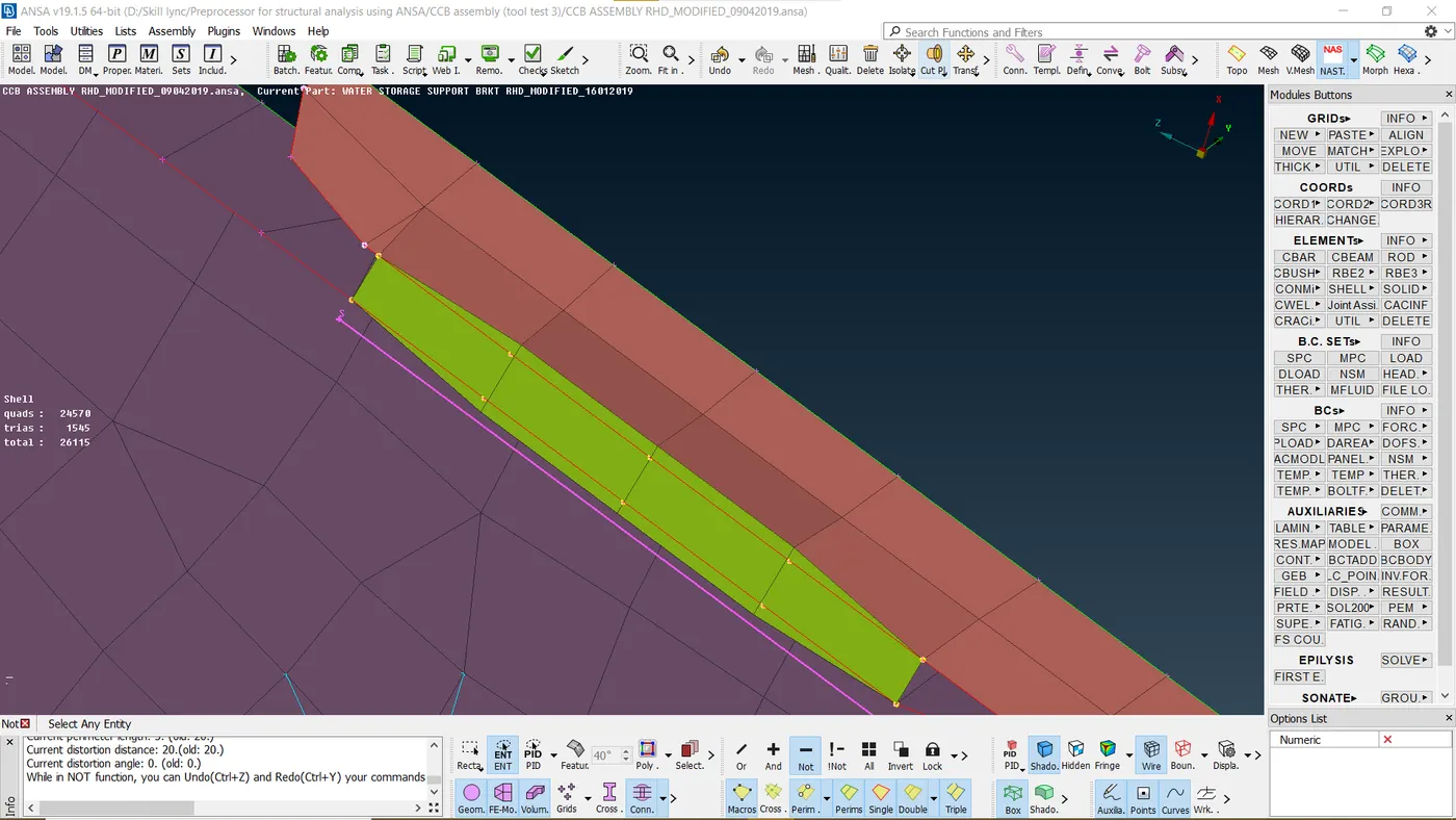
10. Seam welds were used to connect all different parts into a CCB assembly. According to the location and type of joint, primary row and double row type of seam joints were selected as required.
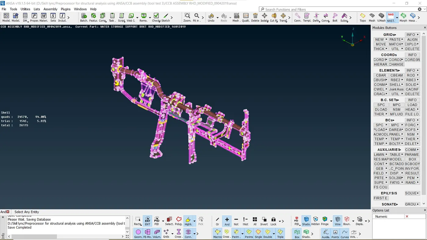
Final model:
Conclusion:
Hot points were added, removed and moved as required to obtain uniform mesh as much as possible. Final mesh obtained was error free and satisfies all the required quality criteria.
All the necessary and required connections are provided using different techniques. Different types of connections used were cluster RBE2, bolt, seam weld, multi node RBE2, two node RBE2.
Therefore, the model of a CCB assembly is ready for further analysis