Generation of volume mesh for Engine Intake manifold using ANSA
Aim: To generate a volume mesh for intake manifold using ANSA. (Unstructured mesh)
|
S.No |
Quality Criteria |
Value |
|
1 |
Target/Average length |
3 |
|
2 |
Minimum Length |
1 |
|
3 |
Maximum Length |
5 |
|
4 |
Tetcolapse |
0.2 |
Introduction: The intake manifold is part of an engine that supplies fuel/air mixture to the cylinders. This manifold can be designed in many ways. The main function of the manifold is to distribute air evenly into the cylinders. It also serves as a mount for the carburetor, the throttle body, fuel injectors, and other components of the engine.
Methodology:
Import the cad geometry of the intake manifold.
Clean up the geometry and look for any topological errors.
2D mesh for target length 3 mm with minimum length 1 and maximum length 5.
Generate a volume mesh from the 2D mesh.
In order to 3D mesh the component, the volume of the model should be defined. Tet collapses should also be removed after generating a mesh.
Step 1:
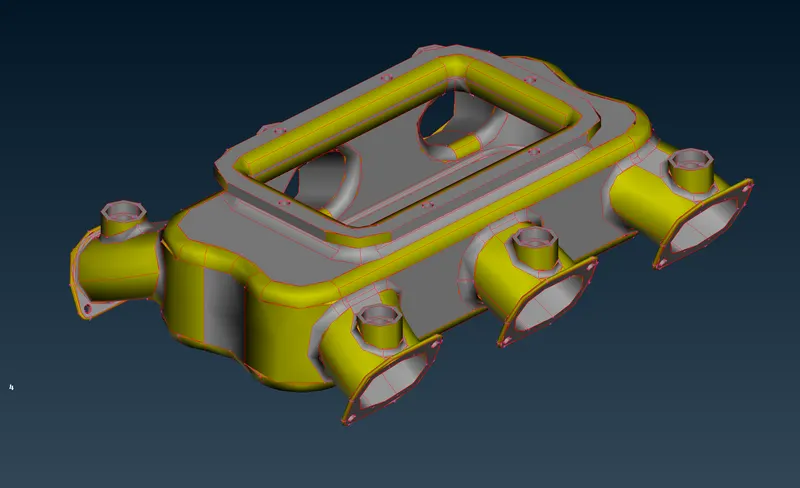
After importing the geometry into ANSA, the length of the perimeter and macros is set to 1 mm to check the quality of the model. Then, a geometry check is run and required clean-up is performed.
Also, a topo function is performed to fix free edges in the model.
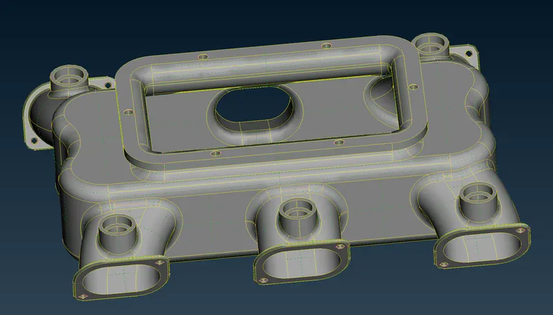
The errors are mostly fixed automatically using 'fix' option in the checks menu.
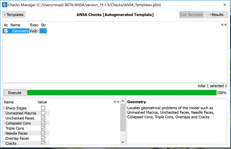
Step 2:
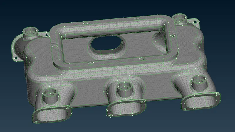
After all the errors are fixed, a quality criterion for the model is set using the required mesh parameters. Meshing is done at curved and smaller regions in the area using 'ortho trias' as they enable better feature-capturing.
For uncurved features, tria mesh is used as it gives almost the same result as an ortho tria mesh while needing lesser computational time.
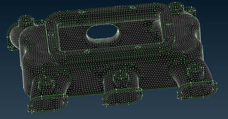
The quality errors in the mesh are then corrected using 'smooth', 'reconstruct' and other options. Also, certain construction lines inside the holes were removed so as to avoid any quality failure.
Step 3:
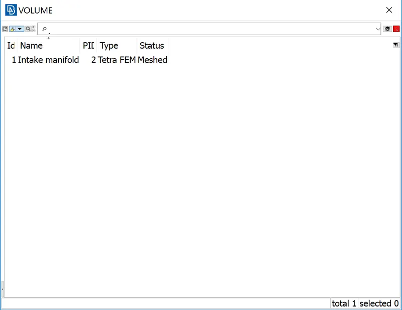
For 3D meshing of the components, the volume has to be defined. Next step is to go to the list option which to ensure that the volume has been defined.
Now, the unmeshed volume can be meshed using Tetra Rapid or Tetra FEM.
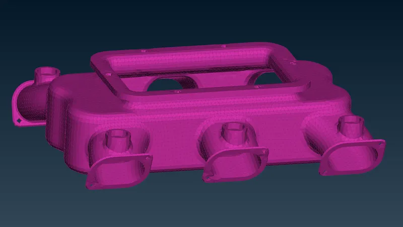
Any elements which do not abide by the quality criteria are taken care of using 'align', 'smooth' or 're-construct' method.
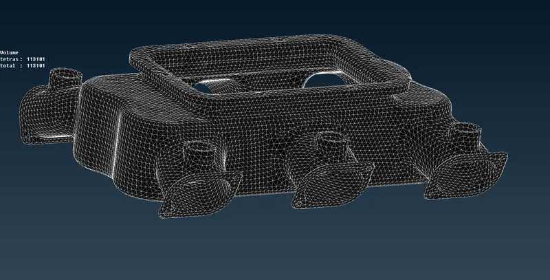
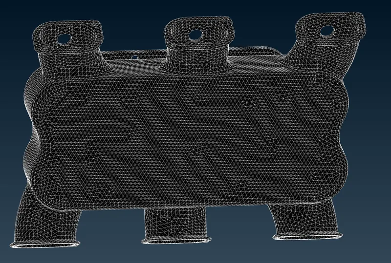
The final picture of the mesh is shown below:
Conclusion:
The given model is imported to the ANSA software and the geometrical errors are fixed.
The surface of the component is meshed with the combination of ortho tria and normal trial elements.
The volume of the component is defined and meshed using tetra FEM elements.
The kinks and dips are eliminated.