To simulate oil-sloshing effect inside a gear box using user defined function.
OBJECTIVE: To simulate oil-sloshing effect inside a gear box using user defined function.
THEORY:
SLOSHING
In fluid dynamics, slosh refers to the movement of liquid inside other object (which typically is also in motion). The liquid must have a free surface to constitute a slosh dynamic problem, where the dynamics of the liquid could interact with the system to alter the dynamics of the system in a significant amount.
The effect of fluid sloshing can be both good and bad and it entirely depends on the system as well as the need of the end user, in our case where we observe oil-sloshing in a gear box, the sloshing effect is beneficial as it keeps the gear teeth lubricated allowing for longer life of the system as whole.
DYNAMIC MESHING
Dynamic meshing allows us to move the boundaries of cell zone relative to other boundaries of the zone and to adjust the mesh accordingly. The boundaries can move rigidly with respect to each other such as movement of pistons inside an engine.
There is a special case of dynamic meshing called sliding mesh in which all of the boundaries and the cells of a given mesh zone move together in a rigid-body motion. In this situation the nodes of the mesh move in space but the cells defined by the nodes do not deform.
Dynamic meshing can be used to model flows where the shape of the domain is changing with the time due to motion on the domain boundaries. Dynamic meshing can be applied to both single and multiphase flows.
USER DEFINED FUNCTION (UDF)
A UDF allows programmers to create their own routines and procedures that the computer can follow. UDF can be dynamically loaded with Ansys FLUENT solver to enhance the simulation results. They are written in C-language and the sure code file is saved with the extension “.c”.
DYNAMIC MESH FAIL AND NEGATIVE CELL VOLUME ERROR
Dynamic mesh failed error and Negative cell volume detected error are the common forms of error encountered in simulation which involve dynamic meshing.
The reason behind this error can be bad mesh quality. If the mesh quality of majority of the cells is not good enough for both structured and unstructured mesh it may result in computational error.
The other reason could be the volume of the smallest cell even the slightest motion of the boundary of can lead to collapse of the cell thus leading to error.
We also need to make sure that all the edges of the gears are selected even if one of the edge goes missing we will face this error as the missed edge would be stationary and the other boundaries would collapse into it. And give error.
PROCEDURE:
GEOMETRY SETUP
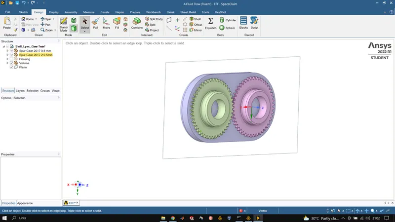
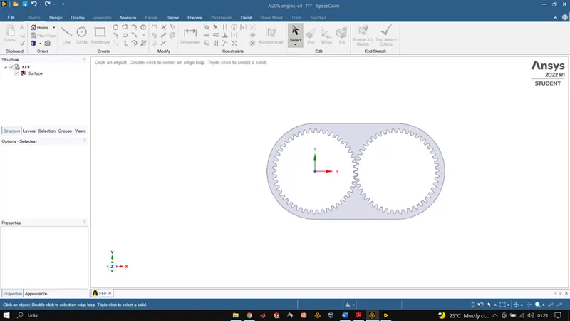
To setup the geometry for simulation we first open space-claim where we load the 3D file of gear box, once the model is loaded, we use the volume extract tool and use the edge selection process to select the volume to be extracted once done we uncheck the casing of the gearbox and then use the plane tool to insert XY plane at origin. Then we use the split body tool using and along the XY plane we cut the volume we created once we complete this we select the volume part of the remaining model and copy it using ctrl+C after that we start a new design file and paste the copied surface on the XY plane and also use the dimension tool to see the dimensions as it will help us in future calculations while creating the regions. Once the surface is pasted we close the geometry and head towards the meshing part.
MESHING
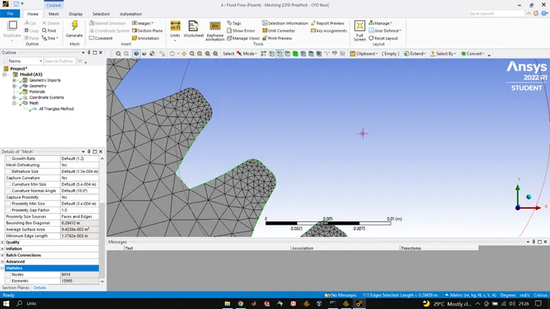
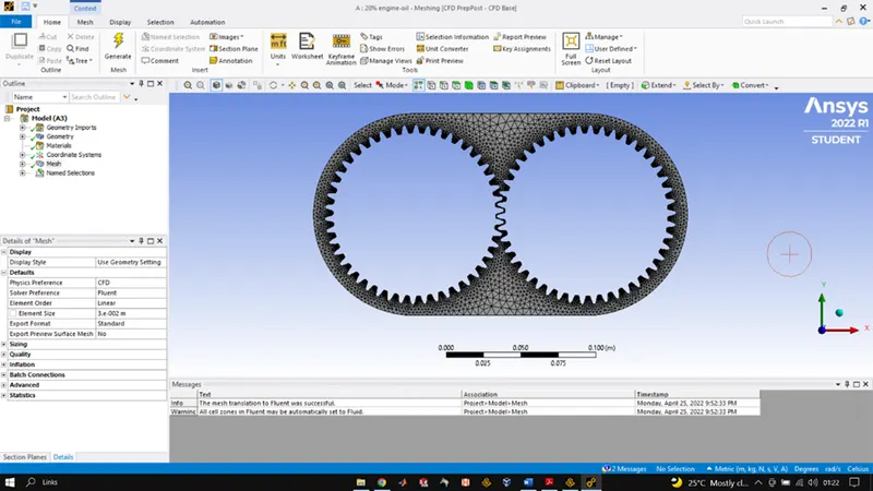
We open the meshing GUI once the geometry setup is completed. We firstly use the edge selection tool and select the edges of each gear tooth very very precisely as even if one edge is missed, we will get negative volume error. After selecting edges, we name them as left and right gear and then head to generate the base mesh once it is generated, we inset method into mesh and select triangles as the method and choose the element size to be 0.003m and also keep the close proximity on and keep the gap as 1. Once all the settings are done, we generate the finals mesh.
FLUENT/SETUP
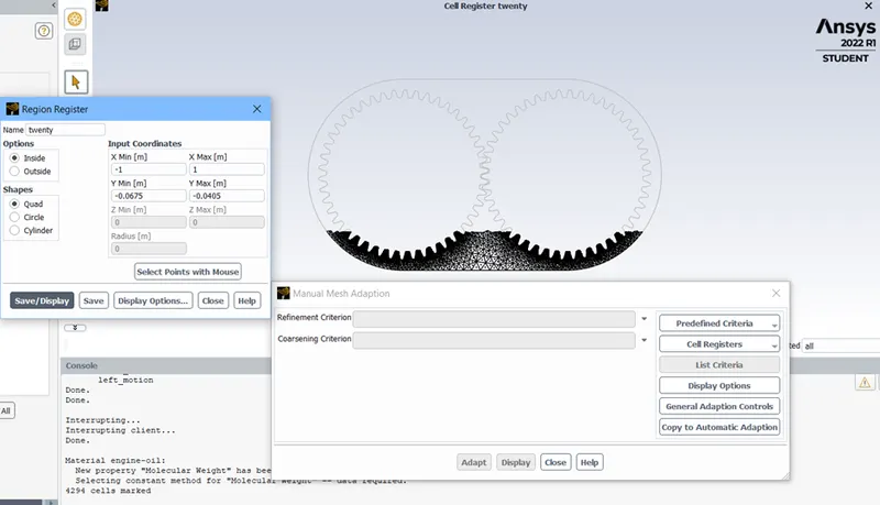
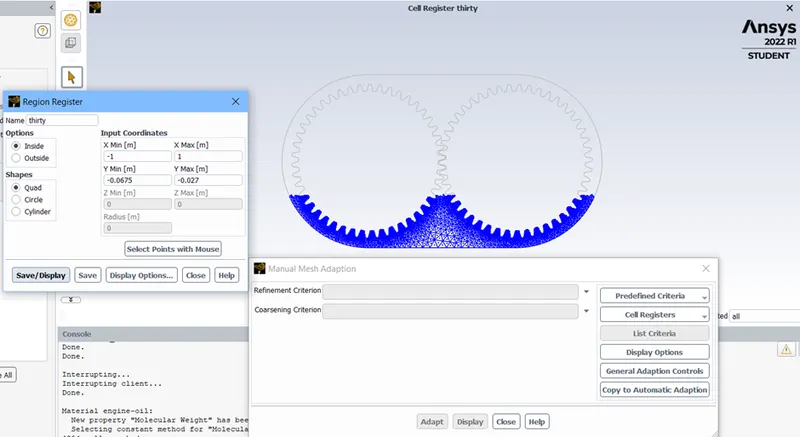
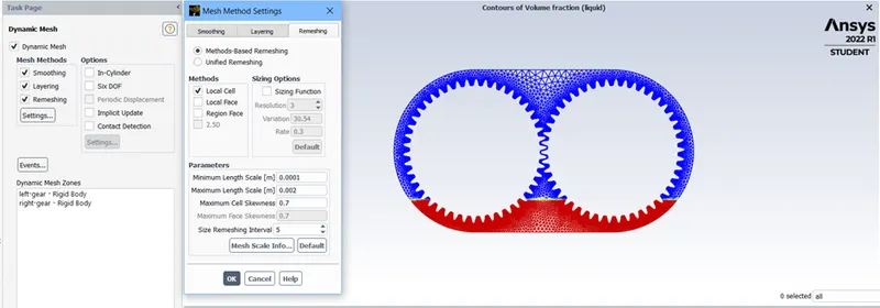
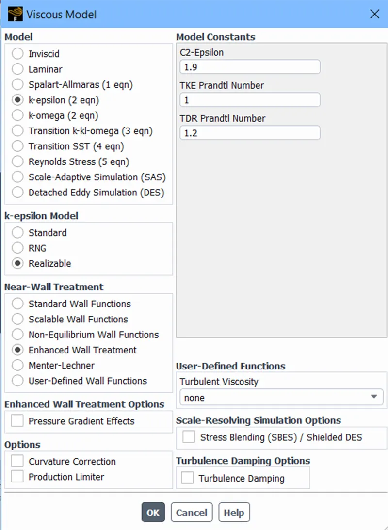
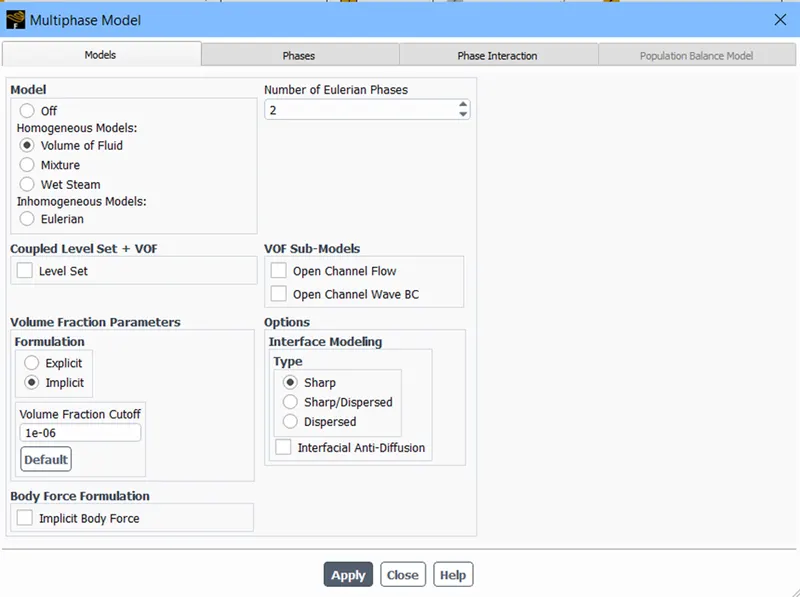
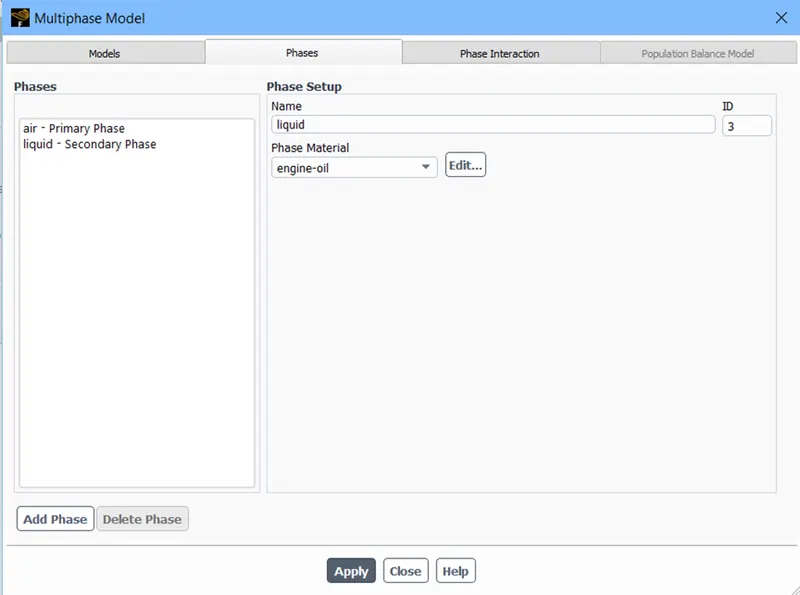
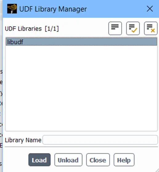
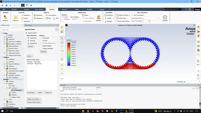
Once the meshing is done, we head to fluent setup where we first the mesh check and make sure that mesh is fine. After that we head towards general physics where we choose the transient time simulation and then we add the required fluids from the fluid data base of materials. In the multiphase model we choose the volume of fluid method and select the implicit way of solving, after that we head towards the phases to appoint each phase with the proper material after that we use the adapt tool in domain to create the required regions for fluid based on the dimensions we took in the space-claim step. Once the regions are created and phases are assigned the UDF is loaded using the functions tool in the user defined section make sure Workbench shortcut as well as the VS-coder command prompt shortcut are in the same directory. Once UDF is loaded we used the dynamic meshing tool in the domain section to set the motion of the left and right gear and also define the remeshing parameters. Once all this is done, we initialise the solution using hybrid method and then do the patching accordingly and after patching we plot the contour of the patching and create animation of the same. And after that we run the simulation using time step size of 0.0001 and number of time steps were 1000.
RESULTS:
20% & 30% IMMERSION ENGINE-OIL
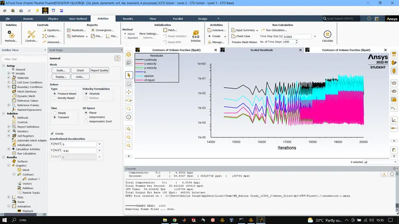
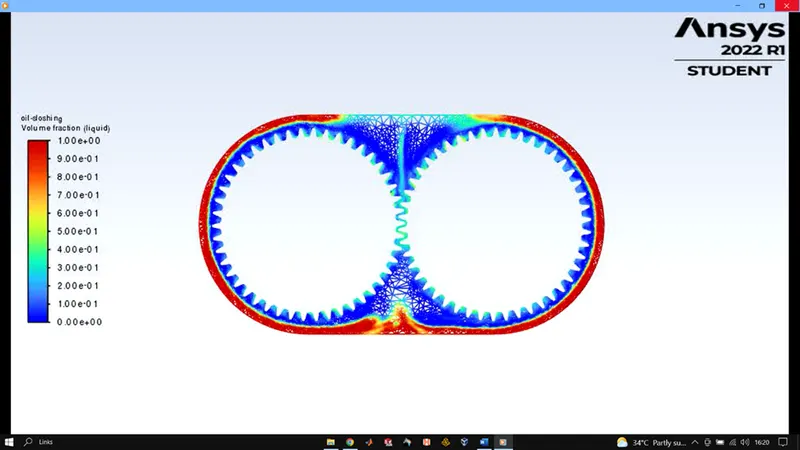
https://youtu.be/HgXdP4WbZTg (due to some unknown issue only a constant position was shown in the animation file saved by fluent hence hand recorded the simulation)
20% & 30% IMMERSION n-heptane
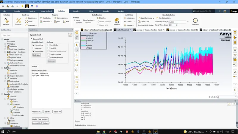
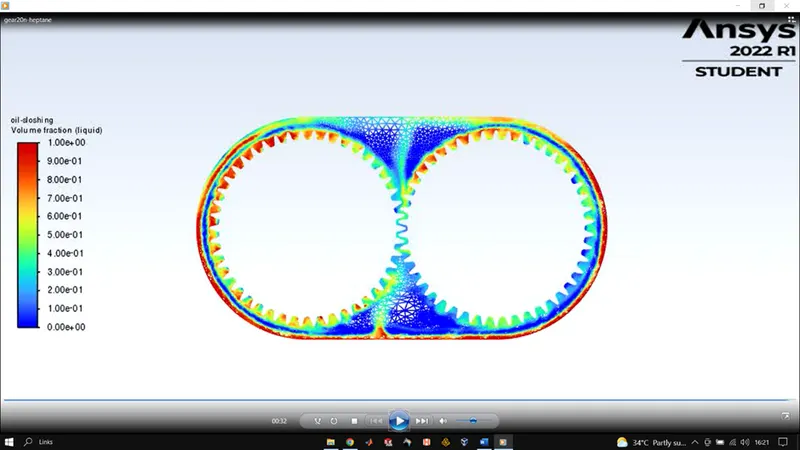
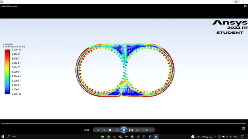
CONCLUSIONS:
Based upon the results of all the cases of simulation it will completely right to say that engine-oil is better lubricant compared to n-heptane.
Engine oil showed a uniform volume distribution on all the gear tooth but n-heptane failed to do so.
And when we see on the basis of immersion of gears in the fluid we observe that during 30% immersion we got better lubrication as more the immersion more would be the liquid for the lubrication purposes.
We were able to simulate nearabout 3.22 rotations which seems to be a nice result give limitations o our computational power and licence.