To plan a structural layout and to create grids using TSD
AIM:-
1. Summarize the user interface in TSD with the for the following items: -
Project Workspace – How to access and usage:-
Project Workspace provide the information releted to the model workspace loading and valedation
This is the Project Workspace
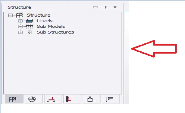
- Scene Content – Demonstrate the use of scene content
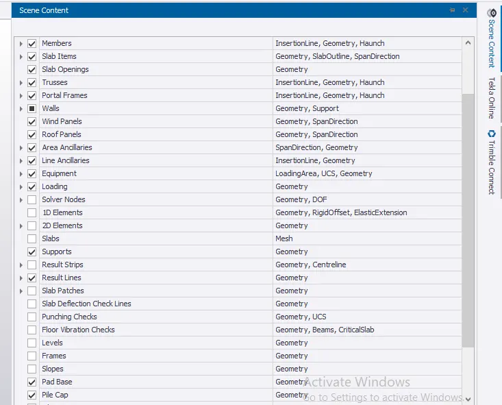
Scene contains the list of all menbers of the structure and helpes in display of a particular member when ticked . the member to be hidden could be unticked so that it disppears from the view
- Create Two Scene Views:-
- Scene views are created to view the project in the different levels /in Three dimensional view
- For instance ,if a G+1 livel is Created,two scene views can be created as fallows
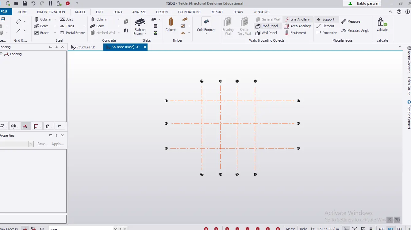
- Draw gride lines and fix levels using construction levels
- New go to project workspaceto choose the levels
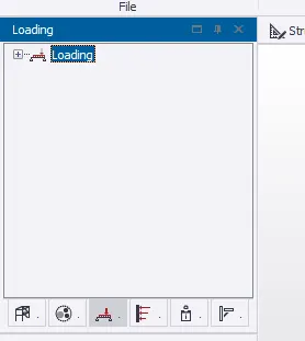
- Loading drop list- How to access:-
- Loading list is seen in the project workspace
- The load cases and list various combinations could be seen

- Properties windows – how to access and usage:-
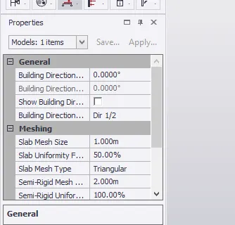
- Properties Window could be seen below the project workspace
- if we select any member / gridlines in the workspace, the propertises pertaining to it will appear under the propertise Windows
2. Create a new file in TSD and set up the settings for a steel building to have member grade FE410 and concrete grade of M30 as per IS codes. The covers for the members to be as per the following input: -
|
MEMBERS |
IN CONTACT WITH GROUND |
ABOVE GROUND |
|
Column |
50mm |
40mm |
|
Slab |
30mm |
25mm |
|
Pile cap |
75mm |
|
|
Foundation |
50mm |
Open the TSD file
And Select the new
< alt>
Select the Seting
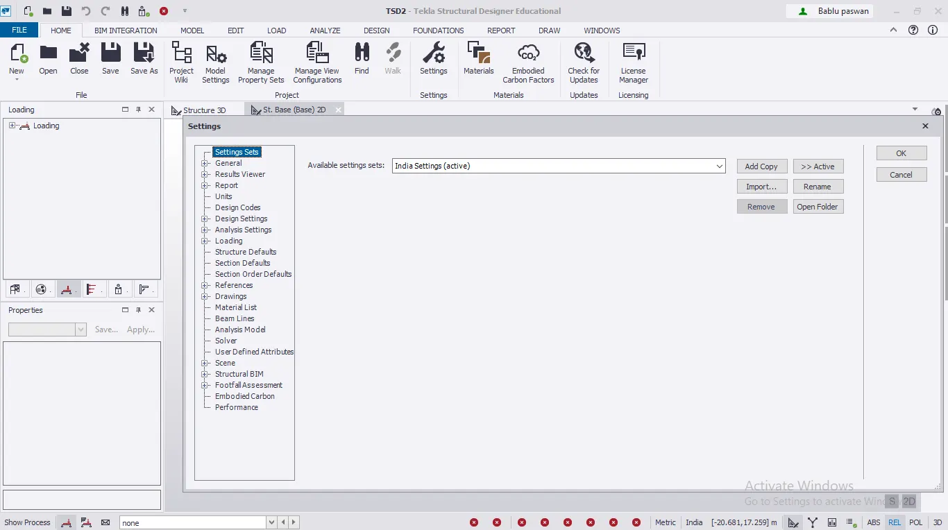
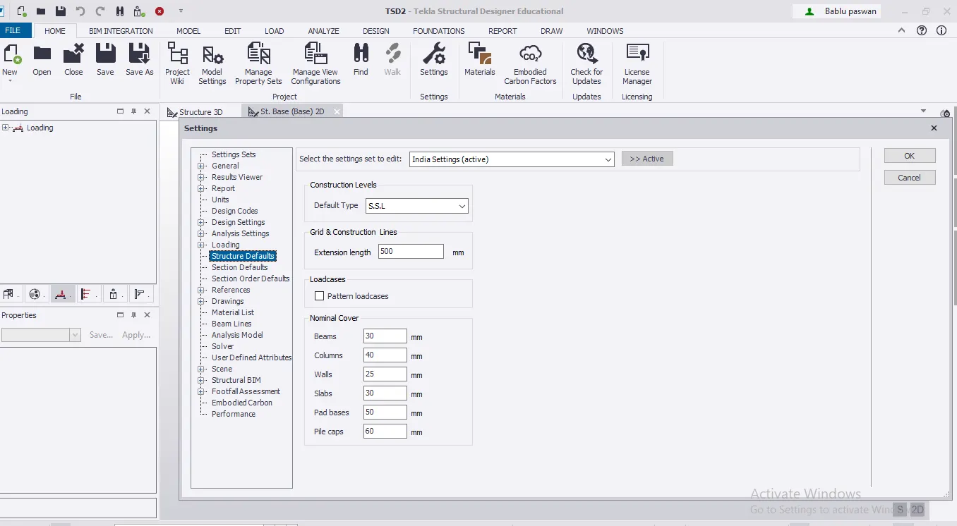
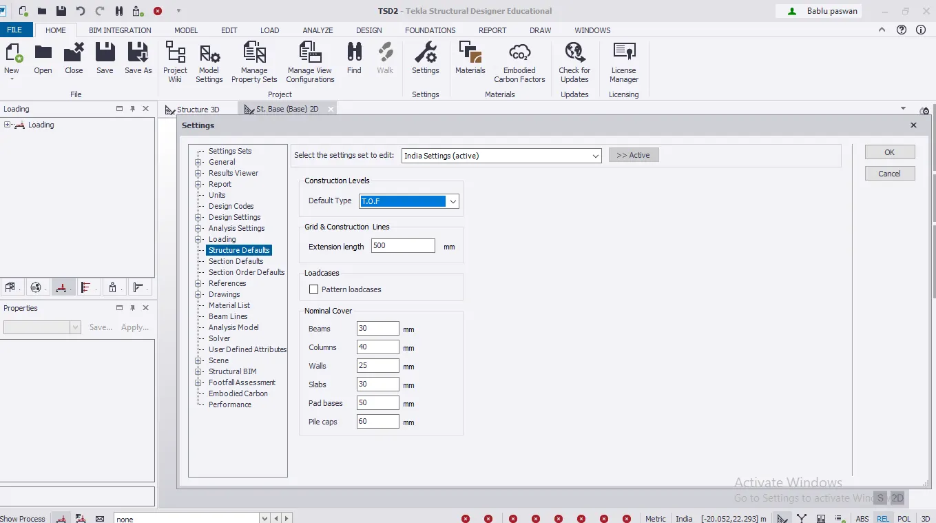
- Similarly, Under structural Defaults, Construction levels,- SSL( Member above Ground ),enter the tothe members as in question
</>
<> </>
<><>3. With reference to the input drawing as per Attachment 1, 1.1, and 1.2 and study the steel building plan and summarize your understanding of the plan. Based on your study assume and explain the location of columns and beam and develop a hand sketch for each plan
Procedure:-
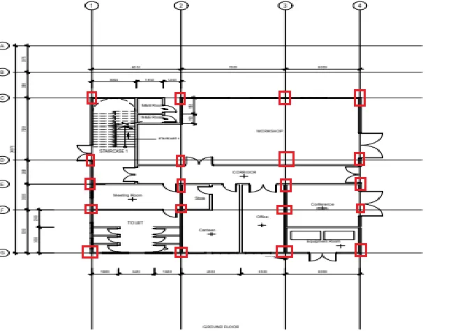
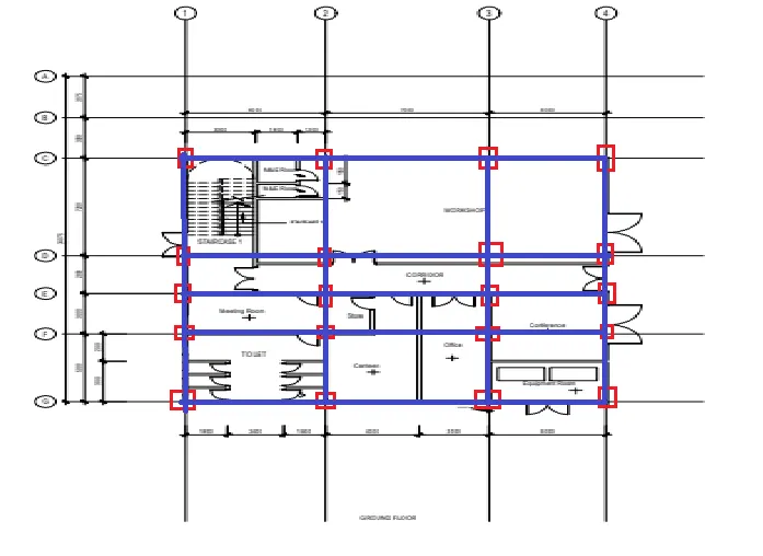
Ground Floor (Attachment 1):-
- Column are placed from the grid lines C through G and 1 through 4
- No problems were encountered while placing column in gride C, E and G
- But in the gride d, there was a door opening and hence the column is shifed to half a column distance
- Similarly in gride F column could not be placed since a door was encountred
- So column are placed 2m frome grid F
Section (Attachment 1.2):-
- The rafters are provided from the roof beam level till the roof level
The purlins are also provided on the rafters
Result :
The beam are columns in the plan are thus preliminarly planned considering the opening available space
4. Model grid lines and construction levels as per Attachment 1. 1.1 and 1.2. All dimensions are in mm
- The base level to be 500mm below ground level.
Procedure:-
- Go to the model - Construction levels
- open the section drawing and enter the level details one above the other
- Start from base level followed by GF,FF,RBL,RL at 0.53m,5.2m,6.8m,4.88m Respectively
- Click ok
- Go to model - Grid - Gride line
- Satrt from the vertical grid line 1
- Check the plan and enter the grid spacing accordingly by using parallel quick grid line option
- After drawing vertical grids, click on prependicular under grids and draw the horizontal grid A
- Draw the subsequent grids with correct spacing
Go to the model - Dimension and mark the dimension
Result
The consrtuction levels and grid lines are thus created as per the given attachent You assest