To plan a structural layout and to create grids using TSD
QUESTION1.
Summarize the user interface in TSD with the for the following items: -
- Project Workspace – How to access and usage
- Scene Content – Demonstrate the use of scene content
- Create two scene views
- Loading drop list- How to access
- Properties windows – how to access and usage
ANSWER:
AIM: To summarize the user interface in TSD with the for the following items: -
- Project Workspace – How to access and usage
- Scene Content – Demonstrate the use of scene content
- Create two scene views
- Loading drop list- How to access
- Properties windows – how to access and usage
INTRODUCTION: Tekla Structures desinger is used in the design software for steel and concrete detailing, precast and cast in-situ. The software enables users to create and manage 3D structural models in concrete or steel, and guides them through the process from concept to fabrication. The process of shop drawing creation is automated.
PROCEDURE:
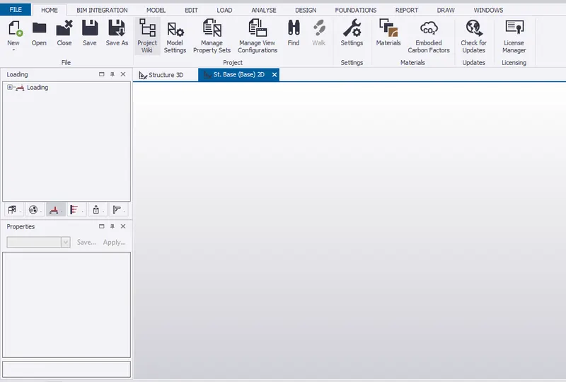
1.Project Workspace-
- open telsa 2021 software>click on file menu>new.
- The project workspace is opened and can be used for modelling.
2.Scene Content-
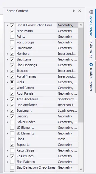
- once new project is opened,at right corner their is a option called scene conctent.
- click on that toolbar,a display appears.
- it deals with the visibility of different geometric,loading and intersection lines of thr project,it will be automatically saved.
- for ex,if we untick grids option,after drwaing grids visibility will be offed.
3.Create two scene views-
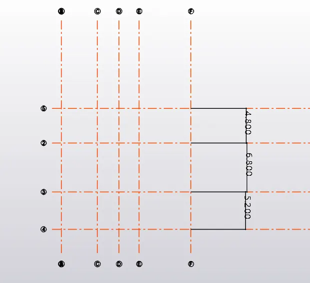
- once new project is created,on the top their will be two options,structure 3d and base 2d.
- click on the base 2d for creating the structure and select grid lines.
- draw grids lines at certain idstance and similarly construction line.
4.Loading drop list-
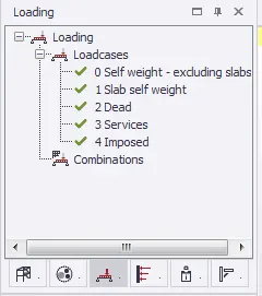
- in order to acess loading drop list-click on the 3rd icon under structure.
- it basically consist of different loading types,combination and pattern that will be applied on structure.
5.Properties windows-
- on the left side bottom corner,properties window appears.
- it usually consist of general information and elemental parameters of the component.
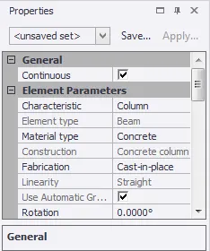
RESULT: The use of user interface of TSD of above items menionted is shown.
QUESTION 2.
Create a new file in TSD and set up the settings for a steel building to have member grade FE410 and concrete grade of M30 as per IS codes. The covers for the members to be as per the following input: -
|
MEMBERS |
IN CONTACT WITH GROUND |
ABOVE GROUND |
|
Column |
50mm |
40mm |
|
Slab |
30mm |
25mm |
|
Pile cap |
75mm |
|
|
Foundation |
50mm |
ANSWER:
AIM: To create a new file in TSD and set up the settings for a steel building to have member grade FE410 and concrete grade of M30 as per IS codes. The covers for the members to be as per the following to be input: -
|
MEMBERS |
IN CONTACT WITH GROUND |
ABOVE GROUND |
|
Column |
50mm |
40mm |
|
Slab |
30mm |
25mm |
|
Pile cap |
75mm |
|
|
Foundation |
50mm |
INTRODUCTION: tekla has option of predefining the material properties,its specification and geometry same as etbas ,but with more options.
PROCEDURE:
- click on new for creating new file.
- from home toolbar>click on materials.
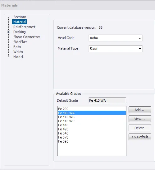
- click on materials,select indian code ans material type as steel,select Fe410 and click on default to set.
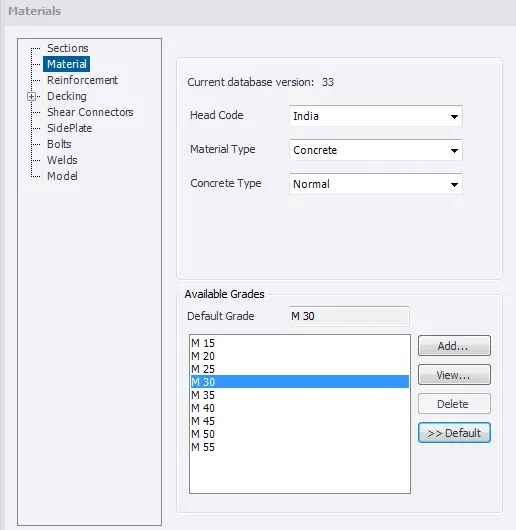
- similarly select on concrete as material type,select M30 and clcik on default.
- in order to change the cover thickness,go to setting>loading>stricture defaults.
- select S.SL type for in contact with ground and enter the values.
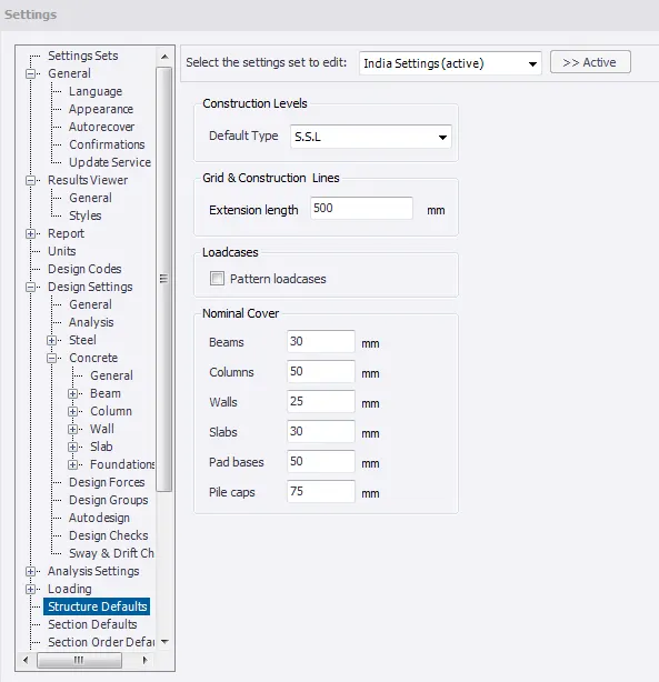
- simialrly select T.O.F for above ground and enter the value.
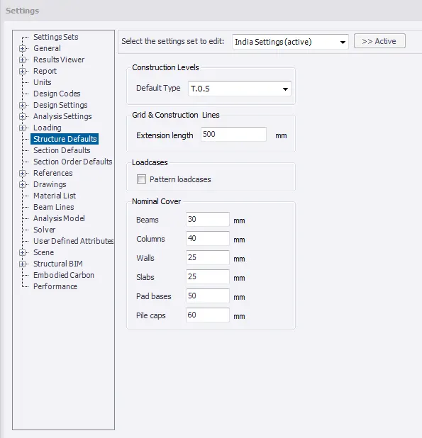
RESULT: The new file of TSD is created and memebers are set to specified grade.Also the civer is changed as per given above.
QUESTION 3:
With reference to the input drawing as per Attachment 1, 1.1, and 1.2 and study the steel building plan and summarize your understanding of the plan. Based on your study assume and explain the location of columns and beam and develop a hand sketch for each plan
ANSWER:
AIM: to study the given three different steel building plan and summarize understanding of the plan.based on stuides to explain the location of columns and beam along with hand drawing for each plan.
INTRODUCTION: Prior step of any structural planning is to understanding the given architectural drawing and check whether the planning satisfy structural features such as geometry,symmetry in mass and stiffness,redundancy .After the analysis,provide the initially column and beam location before foundation and other components.
PROCEDURE:
- In plan with column placment,the column around grid F will cause a probelm in second floor as follow.
- At grid F4 the column will clash with door provided in below floor.
- It doesnt maintain the symmetry also.
- Below provided plan for column and beam,symmetry and uniformity is maintained.Also no clashes with doors.The column at the periphery of the building can withstand certain amount of laterial loads.
- Beam connection along vertical and horizontal ways are provided.Can also provide secondry beam/bracing/perling etc since the roof is slope.
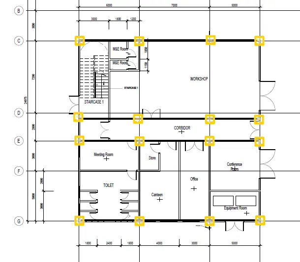
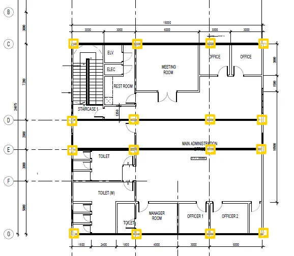
RESULT: Given plan with column is summarized and alternative column and beam design is provided.
QUESTION:-4
Model grid lines and construction levels as per Attachment 1. 1.1 and 1.2. All dimensions are in mm
- The base level to be 500mm below ground level.
AIM: To model grid lines and construction levels as per Attachment 1. 1.1 and 1.2
INTRODUCTION: Gridlines indicate where a building element is placed based from a reference point on plan. Dimensions and gridlines on plans aid in the construction of structural elements (walls and columns). The centerlines of these elements are indicated best to accurately position them on site.
PROCEDURE:
- open new project and go to model toolbar.
- click on construction level and set all 3 levels.
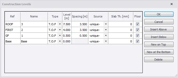
- select grid line option and draw a starting grid 1.
- next select parallel line and draw grid 2,3 and 4.
- similarly repeat the same for horizontal grids.
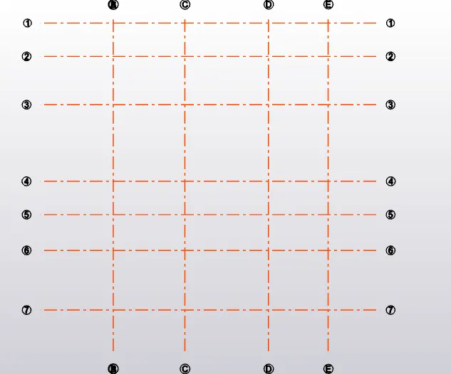
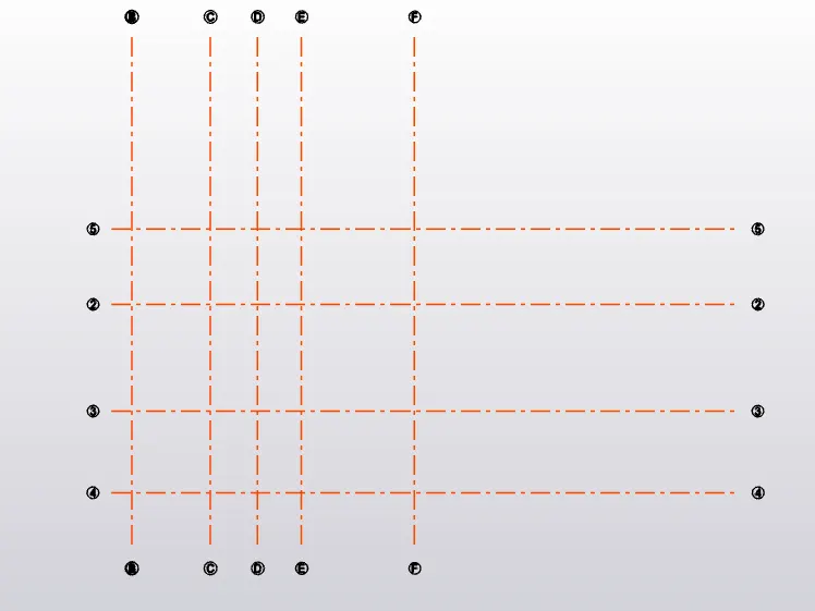
RESULT: The construction level and grid lines are modeled as per attachment files.