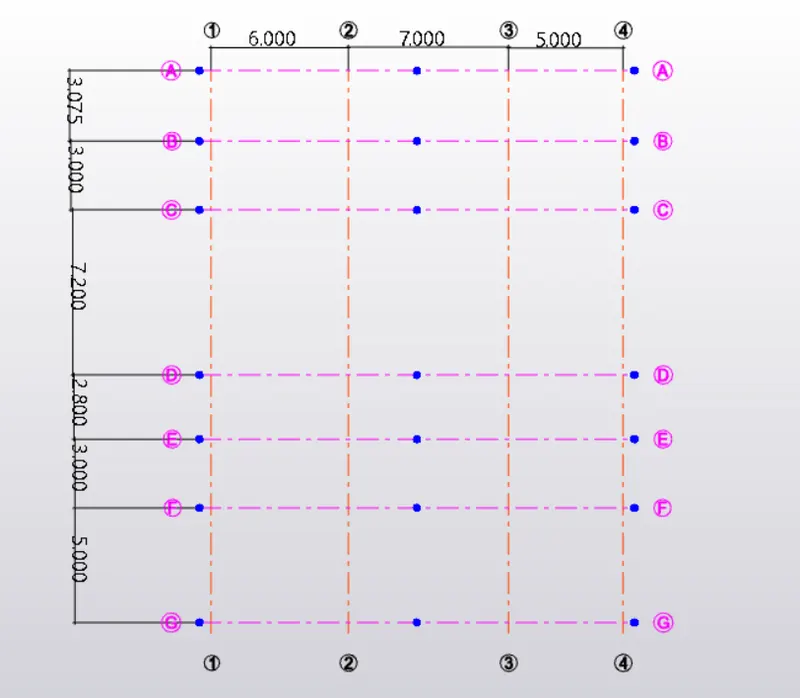
To plan a structural layout and to create grids using TSD
1. Summarize the user interface in TSD with the for the following items: -
- Project Workspace – How to access and usage
- Scene Content – Demonstrate the use of scene content
- Create two scene views
- Loading drop list- How to access
- Properties windows – how to access and usage
AIM : To summarize user interface in TSD
INTRODUCTION : Tekla software is a building information modeling software tool to model all types of structures. It allows 3D modeling, 2D drawinga and access building information.
- Project Workspace – It is the central area of the model. It is used to access structure tree, groups, Loading, wind model, status, connections and report index
- Scene Content – It is used to display and control necessary information in different scene views in a dialog box
- Loading drop list- Views types of loads and its status
- Properties windows – It shows properties of structure tree, groups, loading, wind model, status, connections and report index
PROCEDURE AND RESULTS :
- Open tekla software
- Click on new we get project workspace at right side
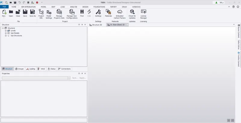
- Now click on windows tab for scene content
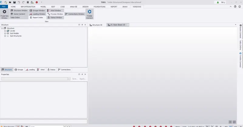
- Different levels of information is displayed in scene content. We can choose content to be displayed for each scene views
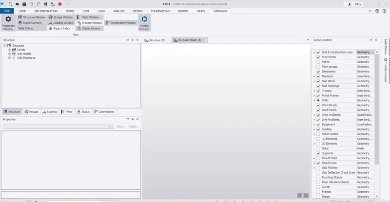
- Two scenes has been created 3D and 2D
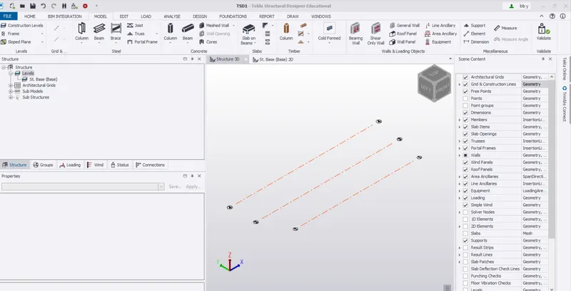
- Click on loading present in project space we get details of list
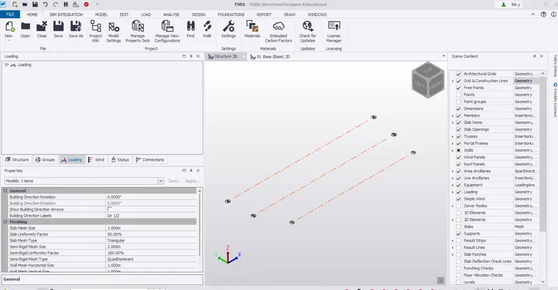
- Go to windows there we can find property windows or we can also find it in tools of project workspace
2. Create a new file in TSD and set up the settings for a steel building to have member grade FE410 and concrete grade of M30 as per IS codes. The covers for the members to be as per the following input: -
|
MEMBERS |
IN CONTACT WITH GROUND |
ABOVE GROUND |
|
Column |
50mm |
40mm |
|
Slab |
30mm |
25mm |
|
Pile cap |
75mm |
|
|
Foundation |
50mm |
AIM : Create a new file in TSD and set up the settings for a steel building to have member grade FE410 and concrete grade of M30 as per IS codes
INTRODUCTION : Setting tool is to enable standard setting of language, results, reports, structural sizes etc. Material tools stores standard material database of the model
PROCEDURE AND RESULTS:
- Open tekla software
- Click on "New"
- New file is created
- Click on "Materials" under File tab
- Again click on materials and add materials under concrete and steel as M30 and Fe415
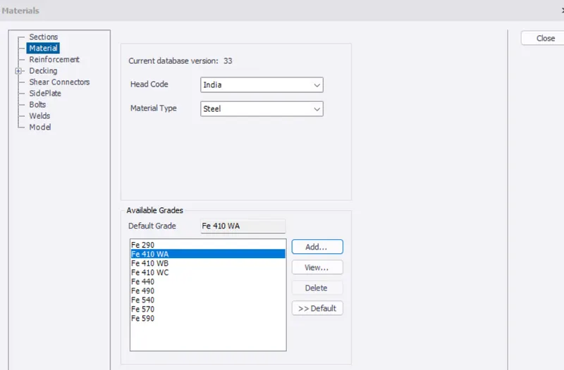
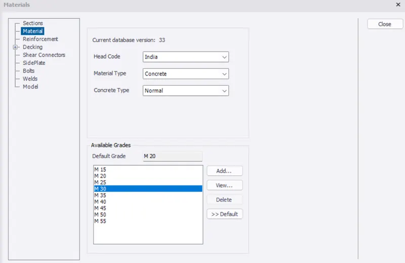
- Go to "Setting" under File tab
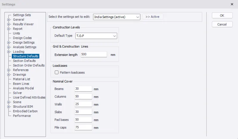
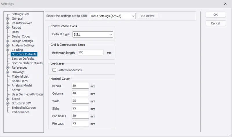
- Click on setting and structure defaults in loading
- Change default type to TOF and assign values
- Change default type to SSL and assign values
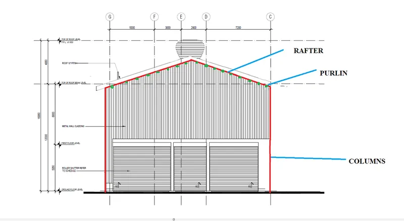
3. With reference to the input drawing as per Attachment 1, 1.1, and 1.2 and study the steel building plan and summarize your understanding of the plan. Based on your study assume and explain the location of columns and beam and develop a hand sketch for each plan
AIM : To create beams, columns, braces, rafters, purlins in the given plan
INTRODUCTION : Columns and beams are placed in a well defined grids.
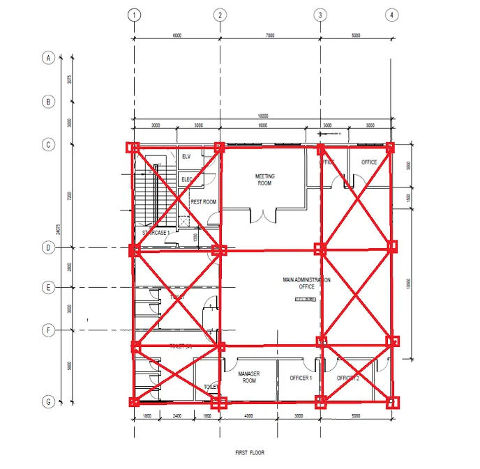
Bracing system : Function of bracing is to provide stability and resist lateral loads, either from diagonal steel members or from a concrete 'core'. For bracing frames, beams and columns are designed only to support vertical load, since the bracing system should carry all lateral loads.
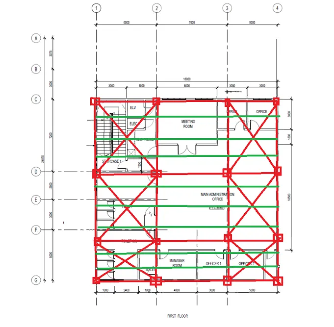
Purlin : Purlin is a horizontal beam or bar used for structural support in structures, most often below the roof. Purlins are supported either by the building's rafters or its walls.
Rafters : A rafter is a structural component that is used as part of a roof construction. Typically, it runs from the ridge or hip of the roof to the wall plate of the external wall.
PROCEDURE and RESULTS:
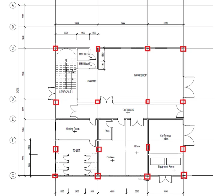
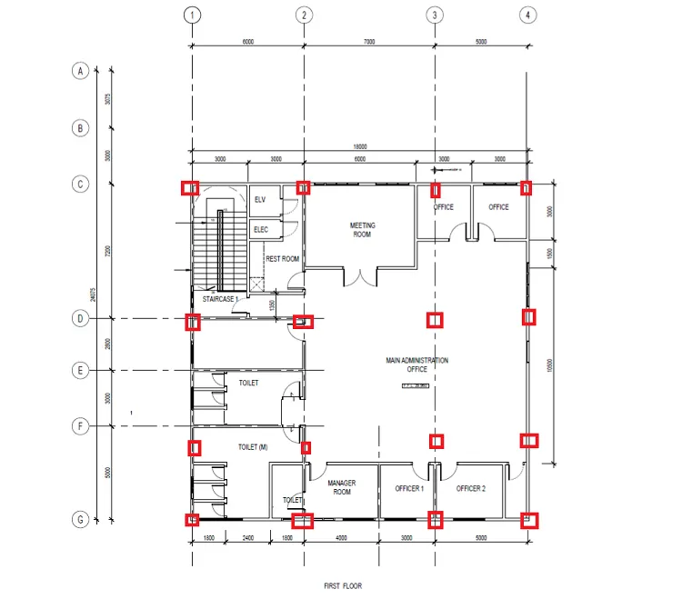
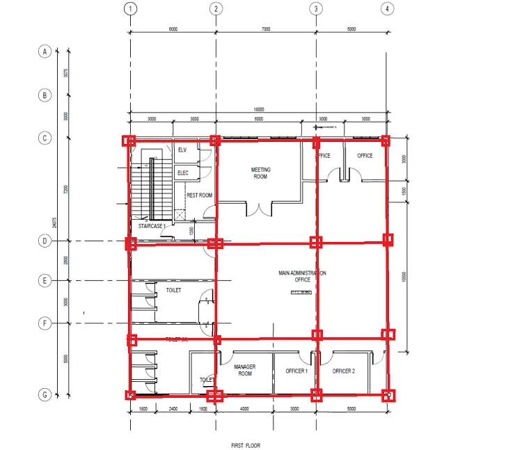
Beams, columns are drawn in ground floor
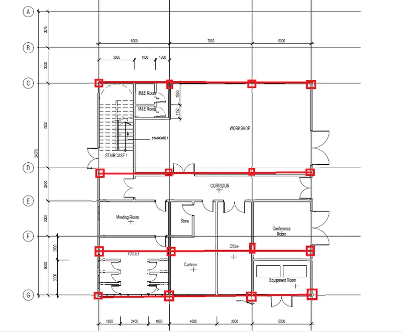
Beams, columns, bracing, rafter, purlins are drawn in the roof level
1. Columns
2. Beams and rafters
3. Bracing system
4. Purlins
4. Model grid lines and construction levels as per Attachment 1. 1.1 and 1.2. All dimensions are in mm
- The base level to be 500mm below ground level.
AIM : To create grid lines based on given plan
INTRODUCTION : A grid represents a three-dimensional complex of horizontal and vertical planes. More than one type of grid lines can b modelled in the software.
PROCEDURE AND RESULTS:
- Open tekla software
- Click on NEW
- Go to "MODEL" tab
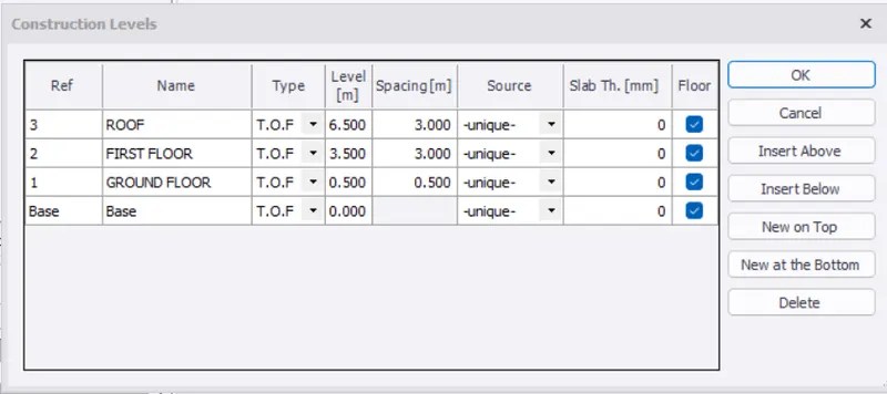
- Click on Construction levels and make changes as shown below
- Click on " rectangular wizard" for drawing grids
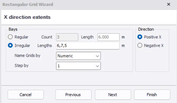
- Similary for Y take 5,3,2.8,7.2,3,3.075
- Renumber the grids and its direction
- Add dimensions to the grids