Drafting of various geometries using Chamfer, Fillet tool in AutoCad
Aim : To create various geometrics using chamfer and fillet tool in AutoCad
Procedure for default settings
- Open autocad application
- Type Qnew and open new drawing
- In create new drawing select wizard
- Select advanced setup
- Set units measurement as engineering, angle as decimal degree, angle measure as east, angle direction as clockwise, area as 9x12 inches and close the tab.
- Now enable the dynamic input, right click dynamic input and choose dynamic input settings. Go to pointer input setting and set default to cartesian format.
- Ortho mode is ON
Procedure for setting object snap
- Type OS in command bar
- Drafting setting box opens in which switch on for necessary tools
- Switch on object snap and object snap modes : Endpoint, Midpoint, Center, Nearest, Intersection, Tangent and Node
- Click Ok
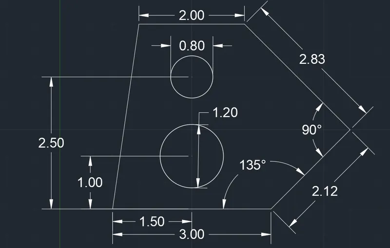
Problem 1 :
Procedure :
- Enter command line L
- Specify the first point 1,1
- Specify next point : 3 by moving cursor towards right
- Specify next point : @2.12<45
- Specify next point : @135<2.83
- Specify next point : 2 by moving cursor towards left
- Enter close
- Draw a circle at a point 2.5, 2 and diameter of 1.2
- Draw another circle at a point 2.5,3.5 and diameter of 0.8
- Using Dimlinear, Dim aligned and Dim angular mark the dimensions
Using Chamfer tool
- Enter command line L
- Specify the first point 1,1
- Specify next point : 3 by moving cursor towards right
- Specify next point : 1.499 by moving cursor towards right (assume line A)
- Specify next point : 1.499 by moving cursor upwards (assume line B)
- Specify next point : 2 by moving cursor upwards (assume line C)
- Specify next point : 2 by moving cursor towards left (assume line D)
- Specify next point : 2 by moving cursor towards left
- Enter close
- Enter Chamfer in command
- Select distance
- Enter first distance 1.499, second distance 1.499 and then select the lines
- Press enter
- Similar way using chamfer tool
- Enter first distance 2, second distance 2 and then select the lines
- Press enter
- Now trim off lines A,B,C,D using trim tool
- Press enter
- Draw a circle at a point 2.5, 2 and diameter of 1.2
- Draw another circle at a point 2.5,3.5 and diameter of 0.8
- Using Dimlinear, Dim aligned and Dim angular mark the dimensions
Result :
Problem 2 :
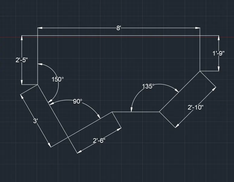
Procedure :
- Set units to architectural
- Set precision in dimstyle to architectural
- Enter line L in command
- Specify first point 1,1
- Specify next point 8' by moving cursor towards right
- Specify next point 1'9'' by moving cursor downwards
- Specify next point @2'10''<-135
- Press enter
- Enter line L in command
- Specify first point 1,1
- Specify next point @2'5''<90
- Specify next point @3'<-60
- Specify next point @2'6''<30
- Join the two end points and close
- Using Dimlinear, Dim aligned and Dim angular mark the dimensions
Result :
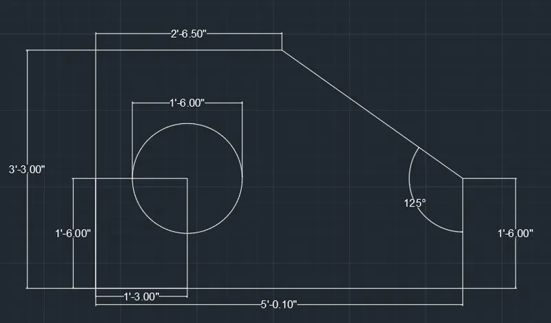
Problem 3 :
Procedure :
- Enter command UNITS
- Change length type to engineering and precision to 0'-0"
- Enter command DIMSTYLE
- Click on modify
- Change primary units to engineering and and precision to 0'-0.00"
- Click okay and close
- Enter command line L
- Specify first point 1,1
- Specify next point 5'0.1'' by moving cursor towards right
- Specify next point 1'6'' by moving cursor upward
- Specify next point 1'9'' by moving cursor upward
- Specify next point 2'5.59'' by moving cursor leftside
- Specify next point 2'6.5'' by moving cursor leftside
- Enter close
- Enter Chamfer in command
- Select distance
- Enter first distance 2'5.59'', second distance 1'9'' and then select the lines
- Press enter
- Draw a circle at a distance of 1'3'',1'6'' from point 1,1 with diameter 1'6''
- Using Dimlinear and Dim angular mark the dimensions
Result :
Problem 4 :
Procedure :
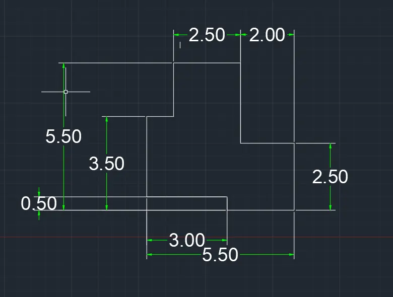
- Enter command line L
- Specify first point 1,1
- Specify next point 0.5 by moving cursor upward
- Specify next point 3 by moving cursor leftside
- Specify next point 3 by moving cursor upward
- Specify next point 1 by moving cursor rightside
- Specify next point 2 by moving cursor upward
- Specify next point 2.5 by moving cursor rightside
- Specify next point 3 by moving cursor downward
- Specify next point 2 by moving cursor rightside
- Specify next point 2.5 by moving cursor downward
- Specify next point 2.5 by moving cursor leftside
- Press enter
- Using Dimlinear mark the dimensions
Result :
Problem 5 :
Procedure :
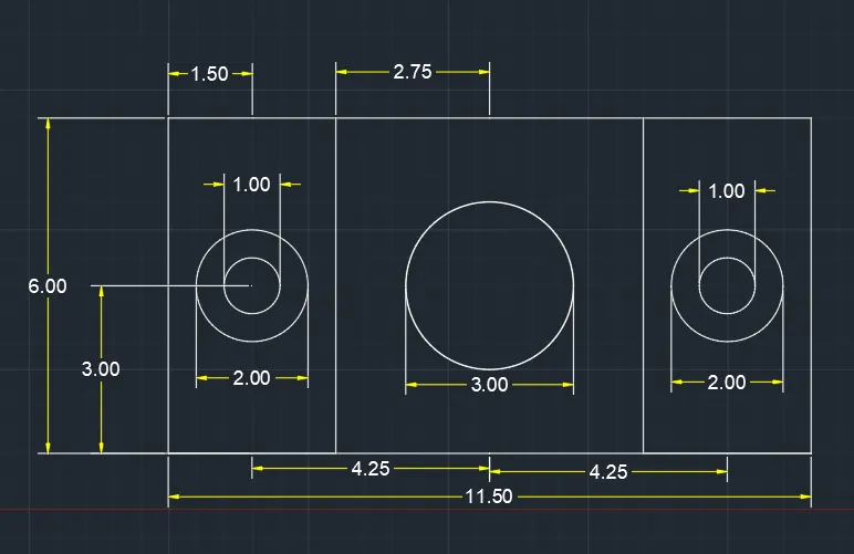
- Draw rectangle
- Specify first point 1,1
- Click on dimension and enter length 5.75 and width 6
- Press enter
- Draw circle at point as center 2.5,4 and diameter 2
- At same point as center draw another circle with diameter 1
- Draw circle at point as center 6.5,4 and diameter 3
- Press enter
- Enter mirror
- Select all objects and enter
- Select first, second point of mirror line and create a mirror image
- Press enter
- Trim off unnecessary lines
- Using Dimlinear mark the dimensions
Result :
Problem 6:
Procedure :
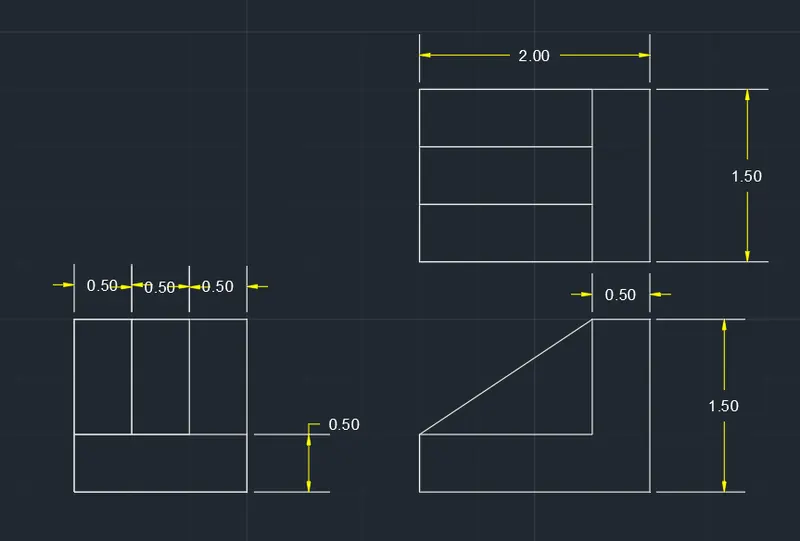
- Draw rectangle at point 1,1 with length and width as 1.5
- Draw another rectangle at point 1,1.5 with length as 0.5 and width as 1
- Copy this rectangle and make another two rectangles
- Paste it beside one another in the rightside
- Press enter
- Take a point 4,1 and draw rectangle with length 2 and width 1.5
- Enter command line L
- Specify first point as 4,1
- Specify next point 0.5 by moving cursor upward
- Specify next point 1.5 by moving cursor rightside
- Specify next point 1 by moving cursor upward
- Press enter
- Enter chamfer in the command
- Enter the distance
- First distance as 1 and second distance as 1.5
- Select the lines and press enter
- Trim off the lines according to diagram
- Draw rectangle at point 4,3 with length as 2 and width as 1.5
- Draw rectangle at point 4,3 with length as 2 and width as 0.5
- Copy this rectangle and make another two rectangles
- Paste it beside one another in the upperside
- Using Dimlinear mark the dimensions
Result :
Problem 7
Procedure :
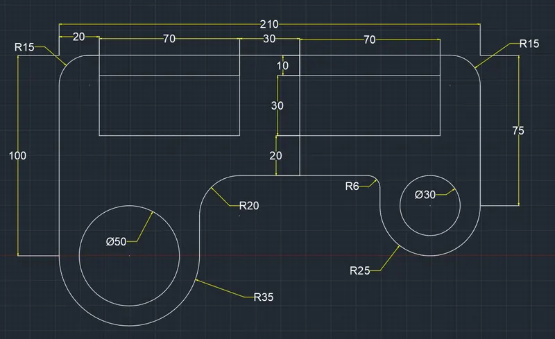
- Enter command line L
- Specify first point 1,1
- Specify next point 100 by moving cursor upwards
- Specify next point 210 by moving cursor rightside
- Specify next point 75 by moving cursor downwards and press enter
- Now draw an arc of radius 25 (diameter 50) using start, end (50) and angle (-180 degree)
- Press enter
- Draw a circle of diameter 30 using center of previous drawn arc and press enter
- Draw a line of length 15 by moving cursor upwards
- Specify next point 90 by moving cursor leftside
- Specify next point 40 by moving cursor downward
- Now draw an arc of radius 35 (diameter 70) using start, end (70) and angle (-180 degree)
- Press enter
- Draw a circle of diameter 50 using center of previous drawn arc and press enter
- Draw two rectangles of length 70 and width 30 at a distance x=20,y=10 at the top of diagram and press enter
- Using fillet tool draw an arc of radius 15 (at @0,100) and press enter
- Using fillet tool draw an arc of radius 15 (at @210,100) and press enter
- Using fillet tool draw an arc of radius 6 (at @160,40) and press enter
- Using fillet tool draw an arc of radius 20 (at @70,40) and press enter
- After fillet, using trim tool trim off the edge lines
- Using Dimlinear, Dimradius and Dimdiameter mark the dimensions
Result :
Problem 8:
Procedure :
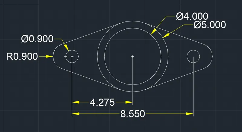
- Draw a circle of diameter 0.9 (circle 1)
- Draw two lines of length 4.275 and 8.55 from the center of circle 1
- At a distance of 4.275 from the center of circle 1 draw two another circles of diameter 5 (circle 3)and 4
- At a distance of 8.55 from the center of circle 1 draw a circle of radius 0.9 (circle 2)
- Draw a line of 1.8 length which is tangent to circle 1(on left side)
- Draw a line of 1.8 length which is tangent circle 2 (on right side)
- Draw an arc using start end and radius (0.9) using end points of line 1.8 on both sides of diagram
- Draw tangent from circle 3 to left side arc using line tool ( specify first point : hold shift+right click, click on tangent)
- Draw tangent from circle 3 to right side arc using line tool ( specify first point : hold shift+right click, click on tangent)
- After drawing tangent trim off the remaining arc
- Remove lines 1.8, 4.275 and 8.55
- Using Dimlinear, Dimradius and Dimdiameter mark the dimensions
Result :
Problem 9
Procedure :
- Set units to architectural
- Set precision in dimstyle to architectural
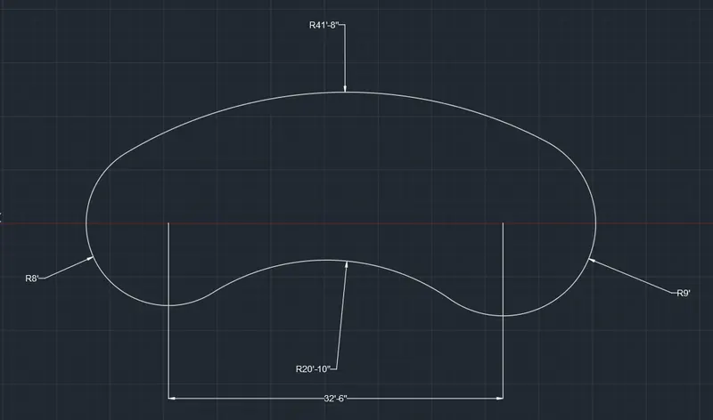
- Draw a circle of radius 8' from point 1,1 (circle 1)
- Press enter
- Draw another circle of radius 9' from at a distance of 32'6'' from start point (circle 2)
- Press enter
- Now draw a circle using tangent, tangent, radius with radius 41'8'' (selecting tangents of circle 1, circle 2)
- Press enter
- Now draw another circle using tangent, tangent, radius with radius 20'10'' (selecting tangents of circle 1, circle 2)
- Press enter
- Using trim tool, trim off extra according to diagram
- Using Dimlinear and Dimradius mark the dimensions
Result :
Problem 10
Procedure :
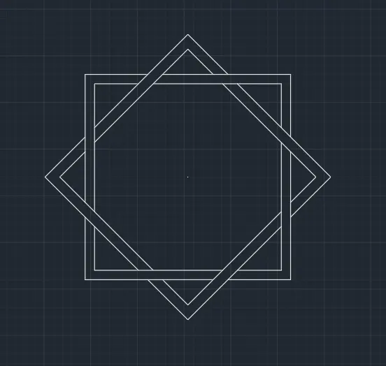
- Enter REC in command
- Specify first point 1,1
- Draw a rectangle with length and width as 10
- Press enter
- Enter OFFSET in the command and offset distance of 0.5
- Select the rectangle and press enter
- Select Polygon
- Enter number of sides of 4
- Specify center of polygon at 6,6
- Then enter the option circumscribed
- Specify the radius of circle @5<45
- Press enter
- Enter OFFSET in the command and offset distance of 0.5
- Select the rectangle and press enter
- Using trim tool, trim off the lines according to diagram
- Press enter
Result :
Problem 11
Procedure :
- Set units to engineering
- Set precision in dimstyle to engineering
- Draw a rectangle of length 20'4'' and width 13'6" from point 1,1
- Draw a rectangle of length 3' and width 4'6" from point 1,1
- Draw a rectangle of length 3' and width 4'6" from point 20'5",1 towards left side
- Draw a rectangle of length 5'4 and width 1'2" from point 7',7''
- Draw a rectangle of length 3' and width 3' from a distance of 6'9'' from the top with an angle of rotation 45
- Draw a triangle of 45 degree with height and base of 2'8" at a distance of 3' from top left side of diagram
- Using mirror tool, similar triangle is made on other side
- Draw a triangle of 30 degree with height 2'0.82" and base of 3'7" at a distance of 3' from top right side of diagram
- Using mirror tool, similar triangle is made on other side
- Using trim tool, trim off the lines according to diagram
- Using Dimlinear and Dim angular mark the dimensions
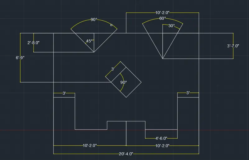
Result :