To plan a structural layout and to create grids using TSD
WEEK 1 CHALLENGE
1. Answer:
Project Workspace:
Using and Gaining Access
Launch the Tekla application.
To open the new window for generating models, click NEW.
Scene Content:
Exhibit how to utilize the material
Click Windows, then Properties, then Scene Content.
It is used to check and uncheck the boxes related to material selection.
Make two perspectives on the scene:
We can switch between two 2D and three 3D dual displays on a new file.
2D perspective.
Drop list loading: How to get to:
Open the "loading window" in Windows.
To load the project workspace, click on it.
Display the procedure for various load combinations, load patterns, and load scenarios.
Windows properties:
access and usage instructions
Navigate to Windows > Properties Windows.
It is employed to assign and modify attributes to various structural components.
2. Answer:
- TEKLA should be opened, the material ribbon clicked, Fe 410 and M20 grade added, and the cover should be changed in the structure default settings to meet requirements.
- Concrete grade M30
- steel grade Fe410
- Cover in contact with the ground
- Cover above ground
3. Answer:
Plan of the Ground Floor:
- It has been noticed that four columns and three beams, each measuring seven, five, and six meters, are required in the X direction.
- Long span beams must therefore be positioned in the X direction.
- We must supply four columns and three beams, each measuring 7.2, 2.8, 3, and 5 meters in the Y direction.
- In addition, subsidiary beams may be inserted between the main beams if needed.
- A secondary beam is located in the center of the staircase.
- Even though it is positioned on the grid, the column support in the top left corner of the equipment room is not aligned with the other columns;
- this is a normal column arrangement.
According to the first floor plan in attachment 1.1
- With the exception of the column height, which changes depending on the roof's slope, the beam and column layout is identical to that of the ground level.
- To minimize the wider spans, individual beams are drawn in accordance with the specifications.
- In addition, subsidiary beams may be inserted between the main beams if needed.
- A secondary beam is located in the center of the staircase.
- It is assumed that the column for the officer 2 room will be placed here. However, as it might not line up with the column on the ground level, the column location on either floor will need to be adjusted.
Attachment 1.2: Elevation
- It is evident from the elevation that the column's height is modified in accordance with the level of the roof.
4. Answer:
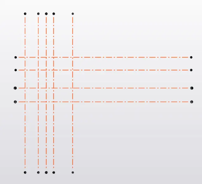
Model construction levels and grid lines in accordance with Attachments 1.1.1 and 1.2. The base level is 500 mm below ground level. All measurements are in millimeters.
Attachment 1 & 1.11
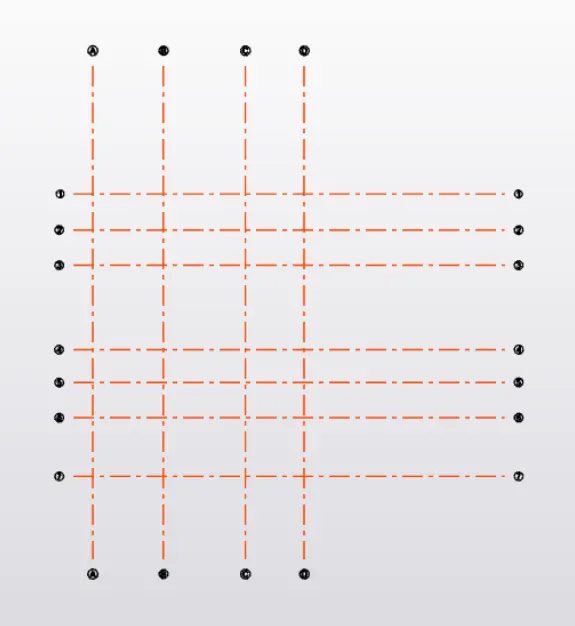
Attachment 1.2