Creating Kitchen layout, Hatching of Architectural elements and sectional view of an Industrial Building in AutoCad
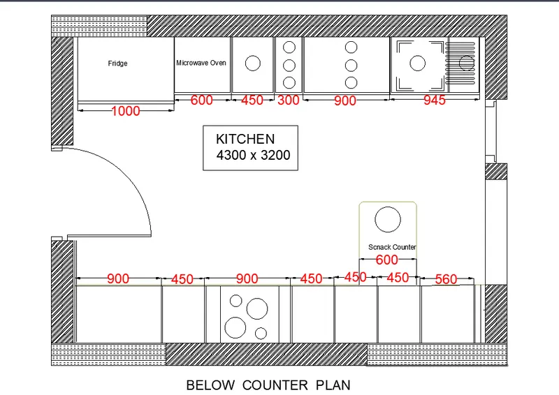
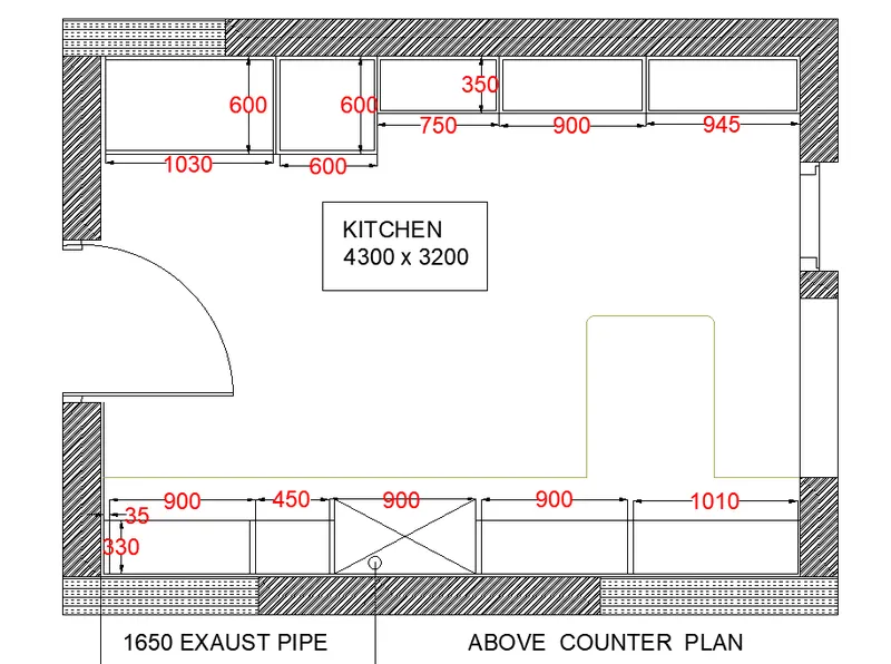
1. Create the layouts of the Kitchen and provide hatches pattern as shown. Also, use blocks wherever required. Provide appropriate dimensions in the plan. Assume the size of doors, appliances and others as per the standards.
Aim: To draw the given kitchen layout in AutoCAD as specified.
Commands Used: Line, Rectangle, offset, Extend, Arc, Trim, Dimension, Mtext, Hatch, Matchproperties.
Procedure:
1. Starting with AutoCAD, Create a new drawing in autocad and units in decimal and precision to 0.0
2. Use the command Limits/Limmax and set the drafting AutoCAD sheet enter 4000,4000 to get all the dimensions in mm
3. Click Z enter and 'a' enter.
4. Take a rectangle command specify randomly the first point and give the dimensions as 4300 x 3200
5. Take offset command give the offset distance as 230mm reference line will be the created rectangle.
6. Use the line command to draft the sketch as given.
For below counter plan - 1000mm x 700mm, 600mm x 600mm, 450mm x 600mm, 300mm x 600mm, 900mm x 600mm, 945mm x 600mm - To create top shelves
- 900mm x 600mm, 450mm x 600mm, 900mm x 600mm, 450mm x 600mm, 450mm x 600mm, 450mm x 600mm, 960mm x 600mm. To create bottom shelves
For Above counter plan - 1030mm x 600mm, 600mm x 600mm, 750mm x 350mm, 900mm x 350mm, 945mm x 350mm - To create Top shelves.
- 900mm x 330mm, 450mm x 330mm, 900mm x 330mm, 900mm x 330mm, 1010mm x 330mm - To create bottom shelves
7. take the arc command and select start, center, end to create door for the kitchen room
8. Use the trim command to erase all the unwanted lines and arc
9. Take the dimenstion command and specify all the dimensions for kitchen layout
10. Use the Mtext command and finish up all the write up works.
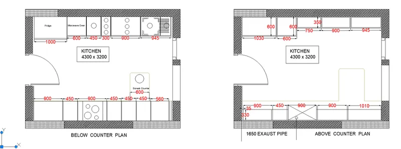
Result: The given sketch is plotted in AutoCAD and shown below.
AutoCAD Result:
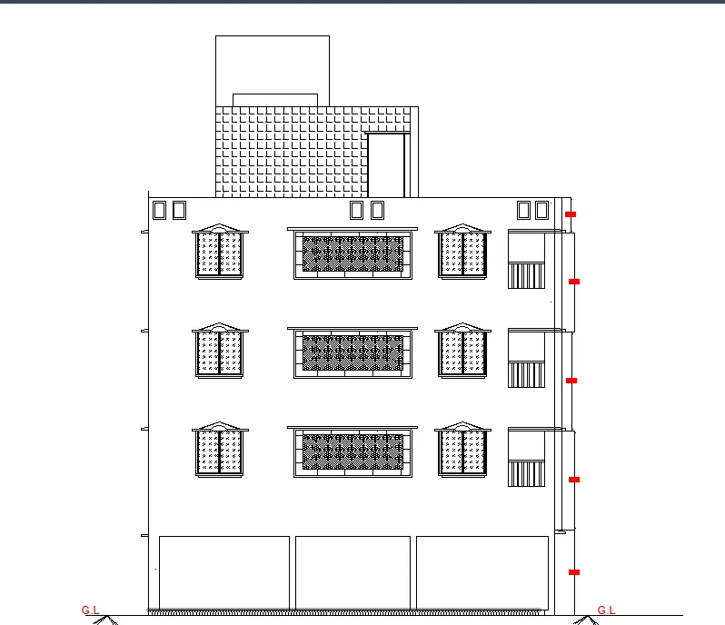
2. Create the elevation of the plan created in the Challenges 7 and apply proper hatch in the walls, doors, windows, and other architectural elements. Refer to the dimensions in Plans and sections in Challenges 7.
Aim: To draw the given elevation and apply hatching in walls, doors, windows, and other architectural elements of a building in AutoCAD as specified.
Commands Used: Line, offset, Trim, Extend, Rectangle, Arc, Hatch
Procedure:
1. Starting with AutoCAD, Create a new drawing in autocad and units in decimal and precision to 0.0
2. Use the command Limits/Limmax and set the drafting AutoCAD sheet enter 4000,4000 to get all the dimensions in mm
3. Click Z enter and 'a' enter.
4. From the plan of challenge 7, taking the same reference plotting the elevation section.
5. Take the line command and extend it horizontally from the plan and suspend the projections.
6. Use the command offset 150 from the groundlevel.
7. Again offset, 2450 to create Groundfloor, 2850 as first floor, 2850 as second floor and 2850 as third floor, and offset of 1000 to create parapet wall.
8. Use offset distance of 2500 for the MUMTY from the terrace level.
9. Use offset distance of 600 and 1200 for OverHeadTank O.H.T
10. offset of 450 for parapet wall of MUMTY.
11. Now drawing the staircase, 1250 is tread and 143.75 for rises and 150mm below the slab, use the offset to create staircase.
12. Windows and chajjas are drafted as per the assumed sizes for W1, W2, W3 & W4.
13. Use the linetype as dash line to show the railings.
14. Use the text Multiline text command and specify the height as 200, to writeup all the documentation.
15. Use Dimlinear command to specify all the dimensions.
16. Use the Mtext command and finish up all the write up works.
17. Take the command hatch to hatch the objects with the change of scale until it fits the selected objects, and to differentiate each objects as shown below.
Use glass hatch for the window, brick for 150mm elevated wall from GL.
Result: The given sketch is plotted in AutoCAD and shown below.
AutoCAD Result:
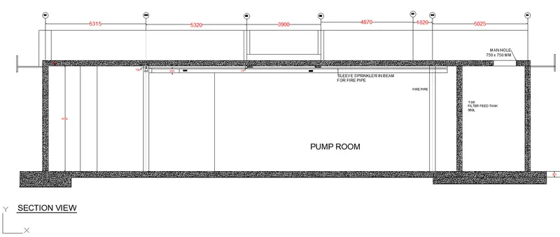
3. Create the section view of an industrial building as shown in Figure. Provide appropriate hatches and dimensions wherever required. Also, provide annotations to the drawing.
Aim: To draw the given section view of an industrial building in AutoCAD as specified.
Commands Used:
Procedure:
1. Starting with AutoCAD, Create a new drawing in autocad and units in decimal and precision to 0.0
2. Use the command Limits/Limmax and set the drafting AutoCAD sheet enter 4000,4000 to get all the dimensions in mm
3. Click Z enter and 'a' enter.
4. Take a line command draw a horizontal line ramdomly taking any starting point
5. Take a offset command, specify a offset distance of 5850 as taking drawn horizontal line as reference.
6. Take a offset command, specify the offset distance of 300 from the same reference line.
7. Take a offset distance of again 300 from the top horizontal line as shown in the figure.
8. Use the line command and dotted lines to create section view from left column center dotted line 5315, 5320, 3900, 4720, 1020, 5025 to the last centerline of right column (dotted line as shown in the below figure)
9. Use the text Multiline text command and specify the height as 120, to writeup all the documentation.
10. Use the trim command to erase all the unwanted line.
11. Use Dimlinear command to specify all the dimensions.
12. Use the Mtleader command and finish up all the write up works.
13. Take the command hatch to hatch the objects with the change of scale until it fits the selected objects, and to differentiate each objects as shown below.
Result: The given sketch is plotted in AutoCAD and shown below.
AutoCAD Result: