To plan a structural layout and to create grids using TSD
Q1. Summarize the user interface in TSD with the for the following items: -
- Project Workspace – How to access and usage
- Scene Content – Demonstrate the use of scene content
- Create two scene views
- Loading drop list- How to access
- Properties windows – how to access and usagea
AIM & INTRODUCTION : The terms given in question given on the user interface of TSD are to be defined in terms of their usage.
PROCEDURE IN DETAIL :
Ans :1
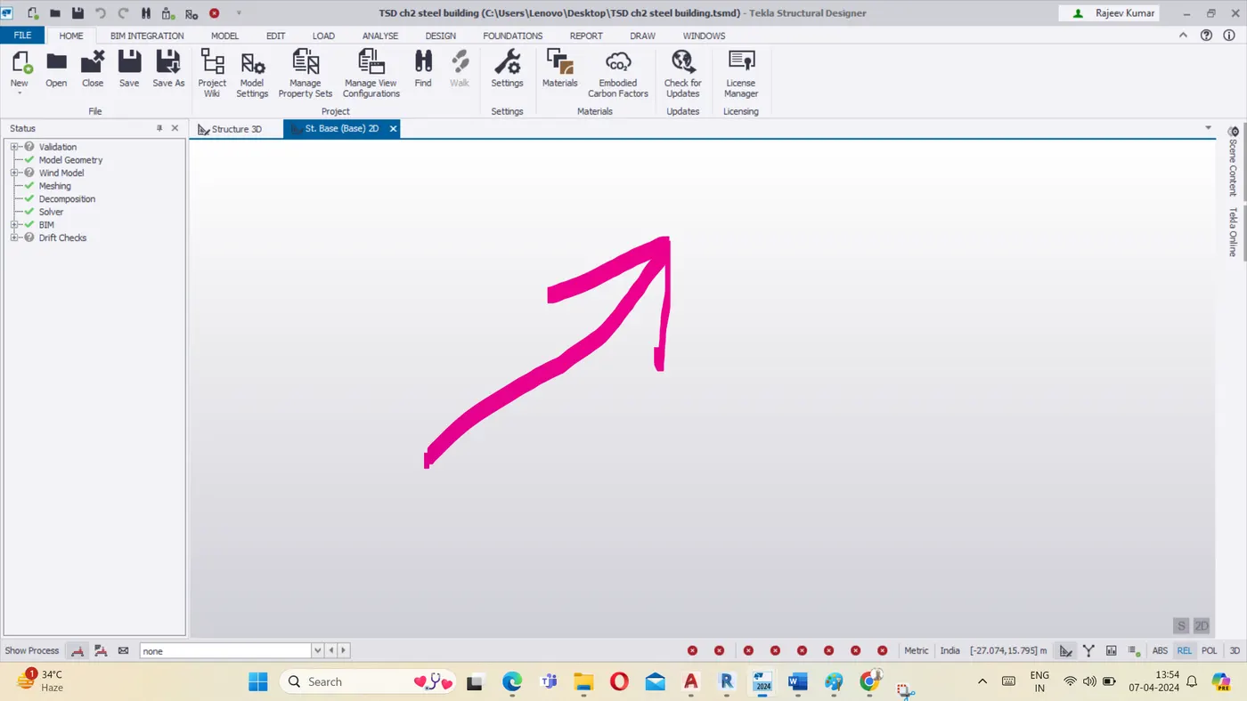
- Project workspace - How to access usage :
- Open the Tekla software.
- Click on Next then Project workspace will appear as shown below :
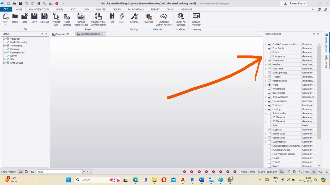
Scene content : Demonstrate the use of scene content :
- Click on the scene content at the left side of screen as shown below
- We can enable or disable the element that are applied to the model
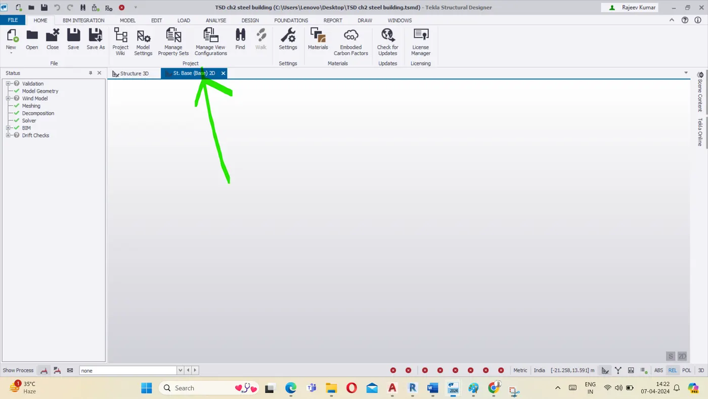
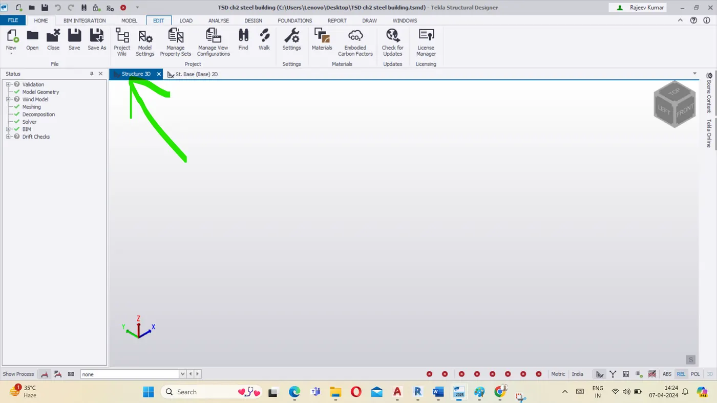
Create two scene views :
- Two scene views are 2D & 3D view
- 2D & 3D views are shown below :
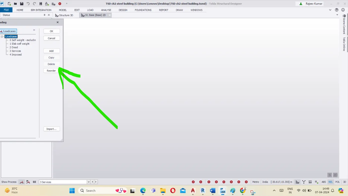
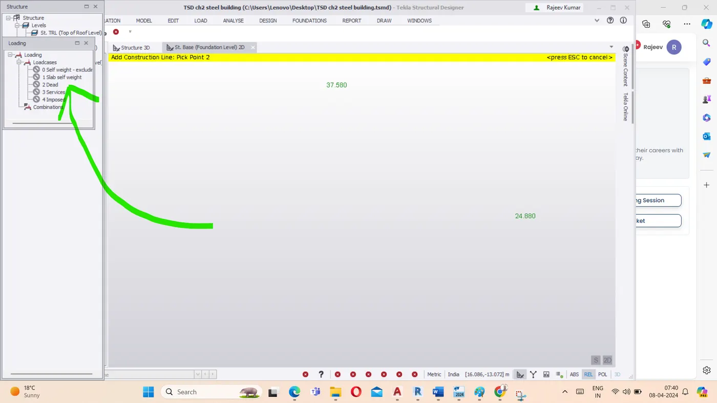
- Loading drop list : How to access :
- Loading drop list is located at the left corner of the status bar in which we can access vaious loads such as dead load, live load , wind load. The load which we create appear in load list drop down.
- In the loading droplist we can see the load cases and load combination and
Properties windows :
How to access and usage :
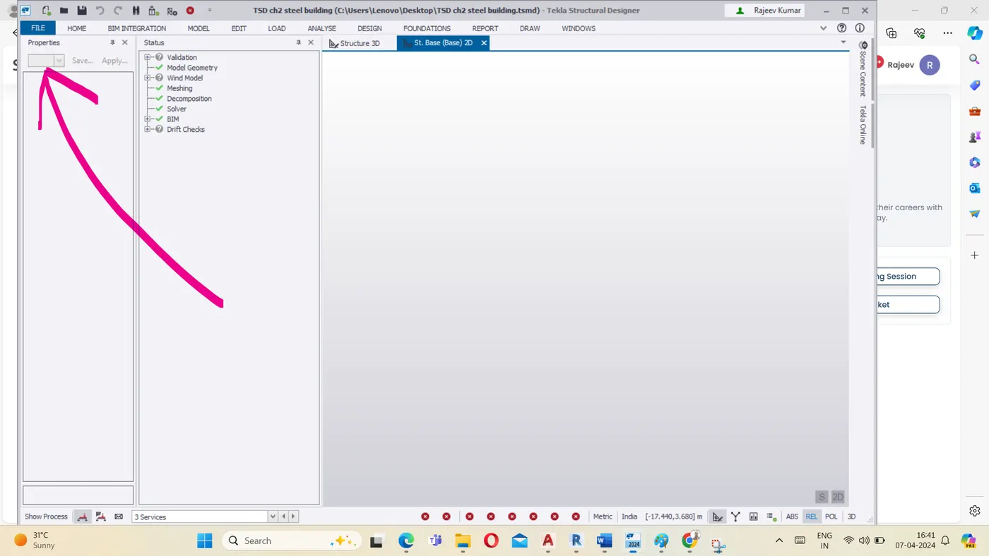
- Open the window option and select the Property window option.
- Property will be vissible as shown below-
- facilitate input , reviw and Editing the model properties. When we click any element of model, its propertis appear in property window from we can Edit its property
-----------------------xxxxxxxxxxxxxxxxxx-------------------------xxxxxxxxxxxxxxx-----------------
Q2. Create a new file in TSD and set up the settings for a steel building to have member grade FE410 and concrete grade of M30 as per IS codes. The covers for the members to be as per the following input: -
Ans :2
|
MEMBERS |
IN CONTACT WITH GROUND |
ABOVE GROUND |
|
Column |
50mm |
40mm |
|
Slab |
30mm |
25mm |
|
Pile cap |
75mm |
|
|
Foundation |
50mm |
Solution : # Go to File Menu and click on New option to create new file
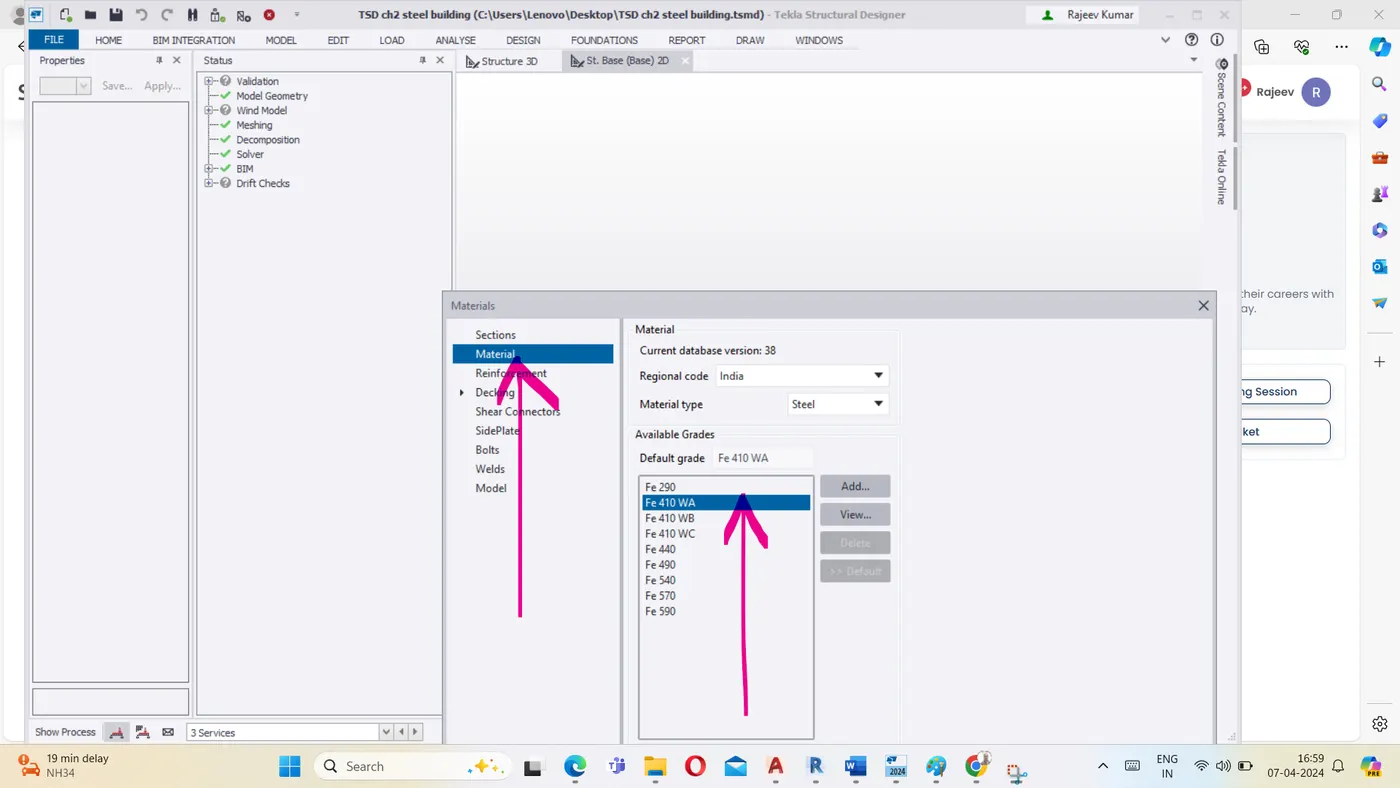
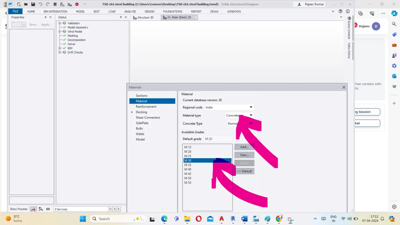
# Select the material option then material tab appears on the screen.
# Select the steel grade as Fe 410 and Concrete grade as M30 from Material tab as shown below-
# Go to Home Tab and click Manage property set
# Click NEW radio button
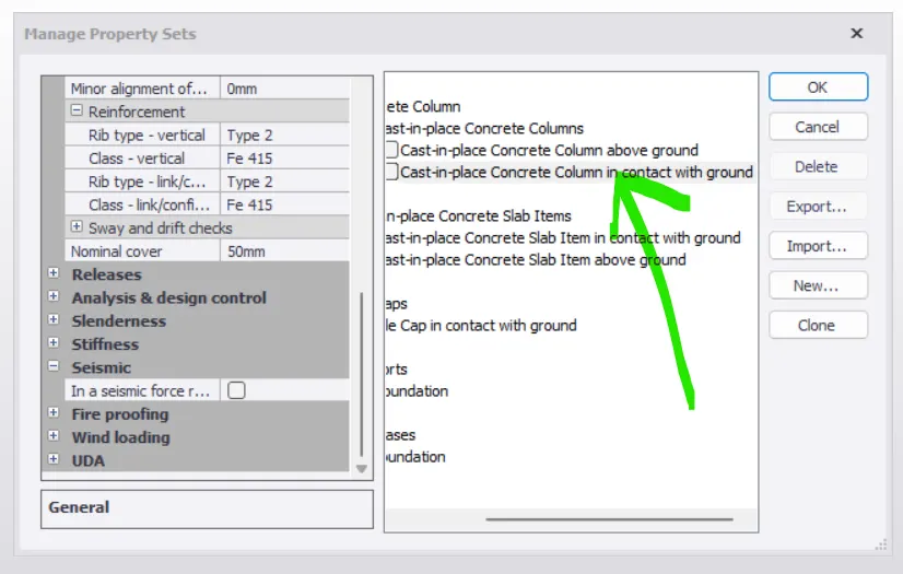
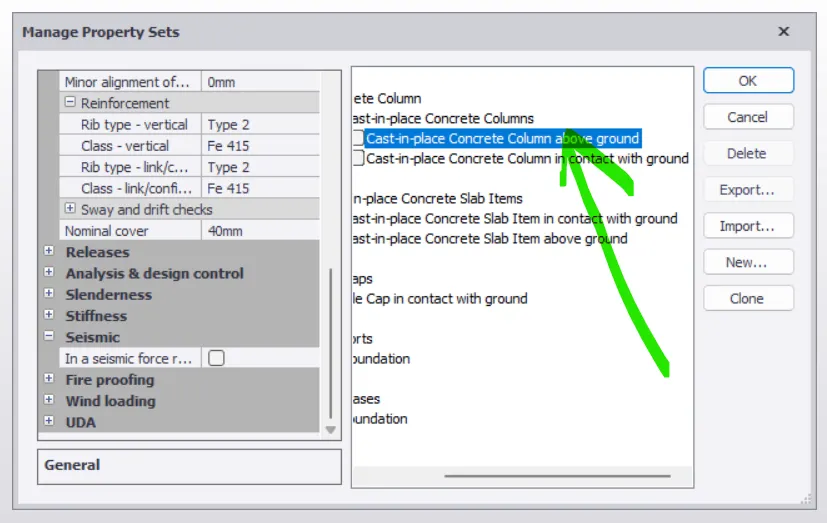
# Go to member and click steel column
# Set Nominal cover of member in contact with the ground as 50 mm as shown below-
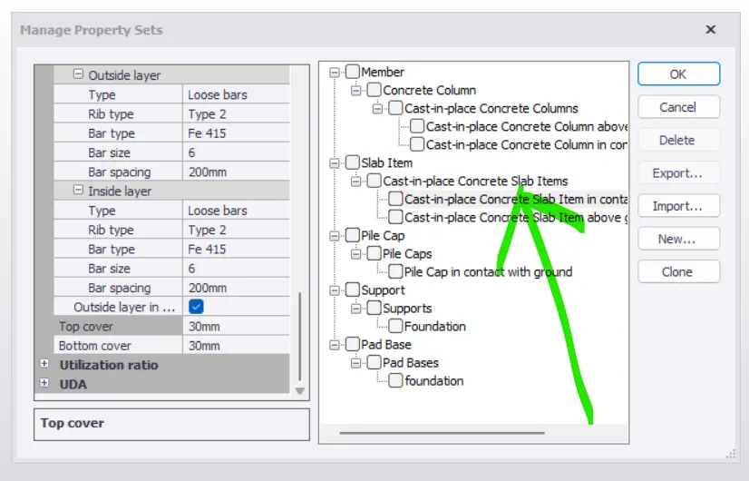
Select slab from material tab and set Nominal cover as 30 mm for material in contact shown below-
Slab in contact with ground , cover= 30 mm
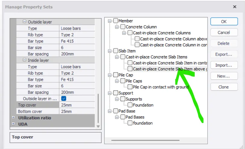
Select slab from material tab and set Nominal cover as 25 mm for material over ground as shown below-
Slab over ground , cover= 50 mm
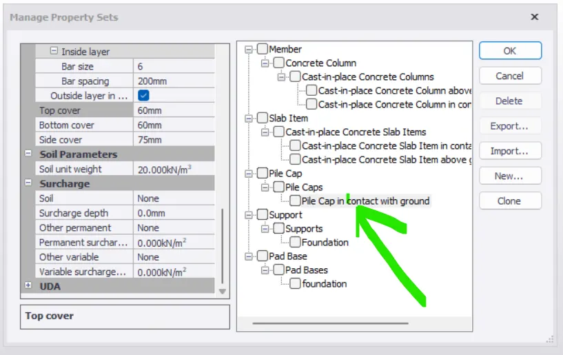
Setting Nominal cover for pile cap as 75 mm as shown below-
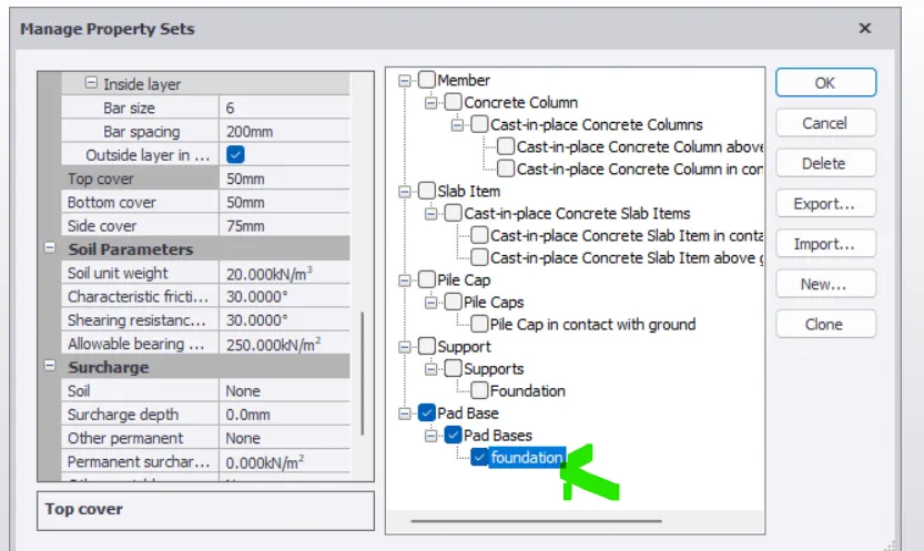
Foundation cover : 50 mm
RESULT : Thus nominal cover to the rebar of different structural elements as required has been set as above.
------------------------xxxxxxxxxxxxxxxxxxxx------------------------xxxxxxxxxxxxxxxxxxxxxx
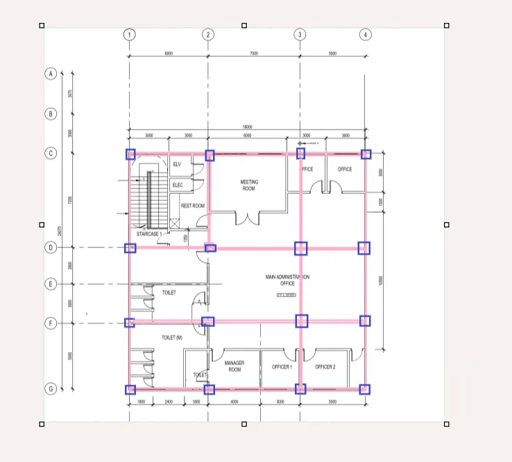
Q 3. With reference to the input drawing as per Attachment 1, 1.1, and 1.2 and study the steel building plan and summarize your understanding of the plan. Based on your study assume and explain the location of columns and beam and develop a hand sketch for each plan
Attachment- 1.0
My understanding of of loacting Beams and Columns is Load transfer path:
- Load is transfer from slab to Primary Beams then to Secondory beams if any then to Column then to Footings and finally to the soil.mColumn to Column spacing should be between 4 to 5 m
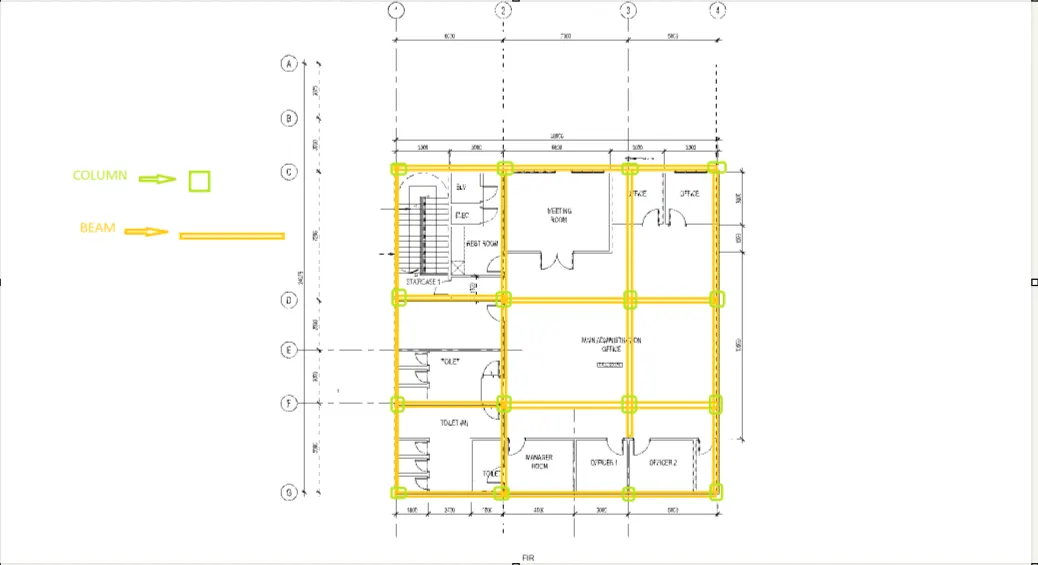
Attachment- 1.1 : Plan of steel Building showing Beams and Column
Attachment -1.2 : Elevation sketch of Building showing Beams and Columns
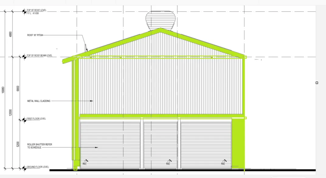
Result : Thus, Hand sketch plan of attached drawing No. 1, 1.1 & 1.2 has been drawn showing the positions of column and beams as above.
--------------------------xxxxxxxxxxxxxxxxxx----------------------xxxxxxxxxxxxxxx------------
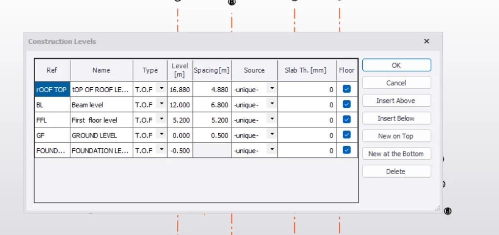
Q 4. Model grid lines and construction levels as per Attachment 1. 1.1 and 1.2. All dimensions are in mm
Ans :4
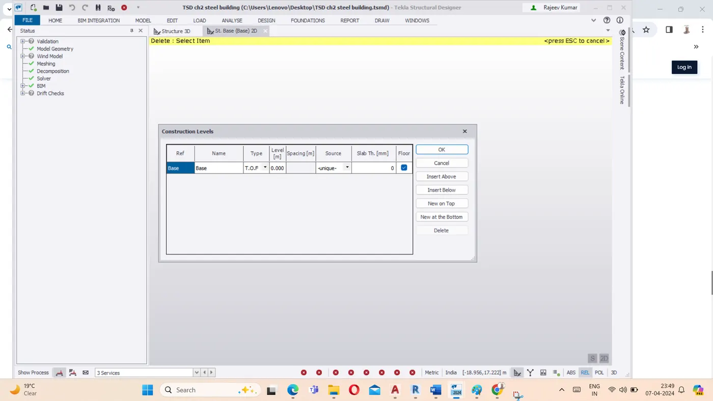
- The base level to be 0.5 mbelow ground level.
- Open the Telka software
- Select the model Tab and then click construction level , the screen will be as below :
Draw levels as required and assign their names as shown below :
- Go to the Model Tab
- Select the Grid line and draw the gridline
- For next grid, select parallel grid line option and draw at required spacing
- After completing grid lines along one direction , select perpendicular grid line option and draw as many grid lines as required.
- Nomenclature of grid lines can be set using property browser.
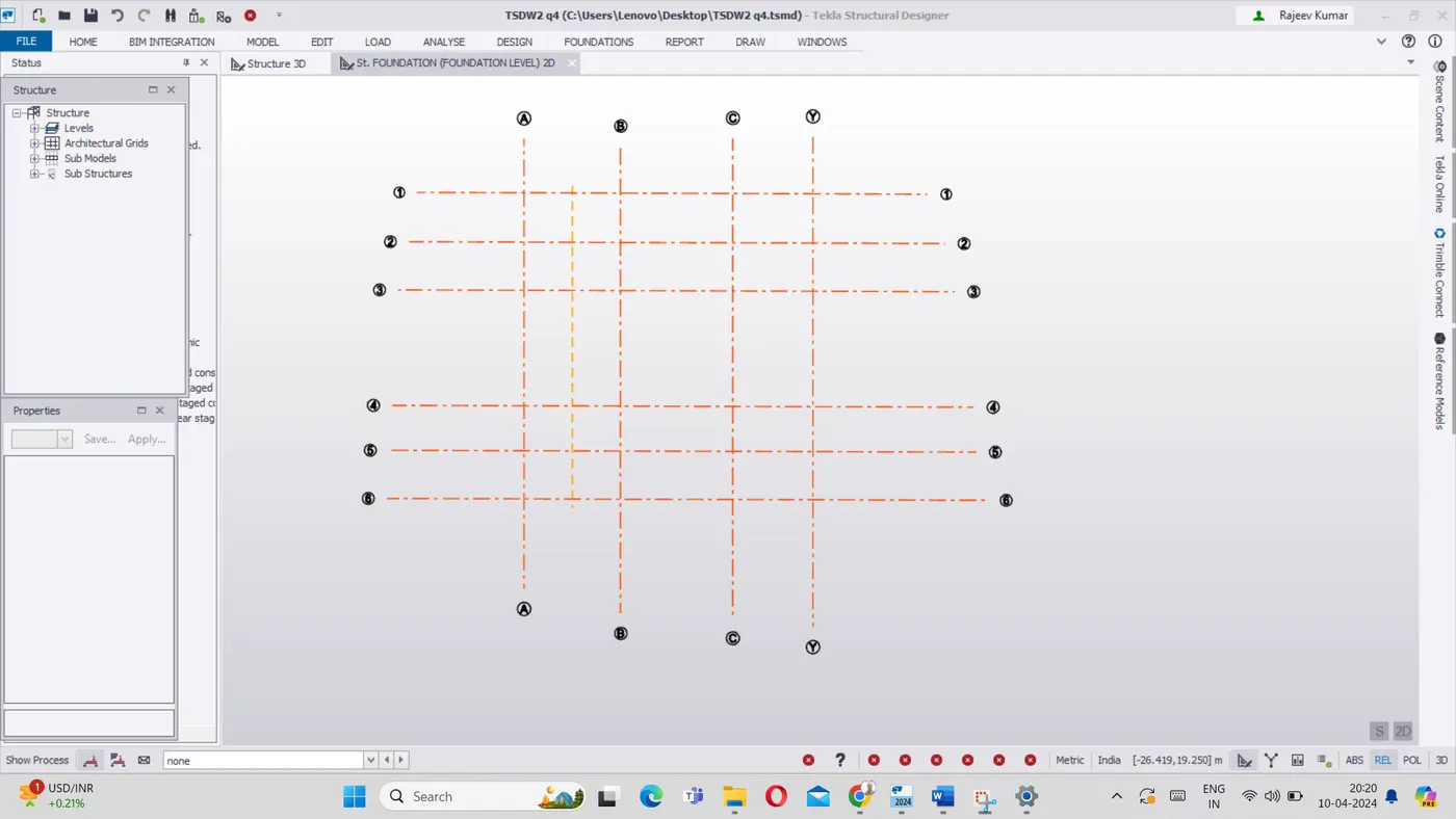
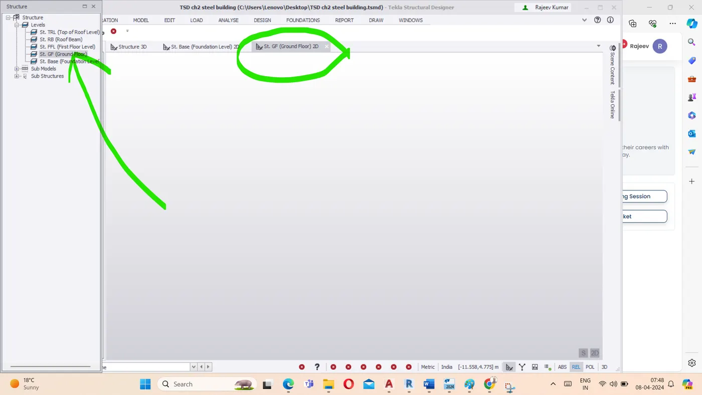
- Select the Ground Floor level for creating Grid lins as shown below-
Go to the Model Tab and click on grid lines as required
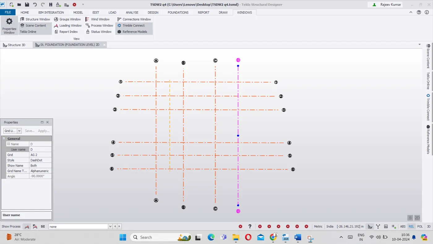
Result : Thus as required Levels and grids has been created as above.
-------------------=xxxxxxxxxxxxx--------------xxxxxxxx-----------------------------------------