To model beams and bracings for industrial steel structures using TSD
WEEK 3 CHALLENGE
Specifics of the structure:
Support: Top and Bottom Fixed-Pinned
Pedestal Size for Concrete: PD1 = 600x600 mm
Steel Beams: MB 300 Steel Column C1:
B1= ISMB 300 was applied to the ground floor principal beams, which included the landing beam of the staircase.
B2= ISMB 250 applied for first-floor principal beams, including landing beams for staircases.
B3= ISMB 225 was submitted for the first floor secondary beams.
B4: ISMB 350 was applied to the roof beams below the rafters and along the ridges.
Rafter: ISMB 400 arranged in rows along the roof's grids.
Ridge= ISMB 400 applied horizontally in the direction of X along the roof beam top level grids.
1. Create beam properties for first floor and model the beams.
Answer:
Ground floor layout for the 2D modified view.
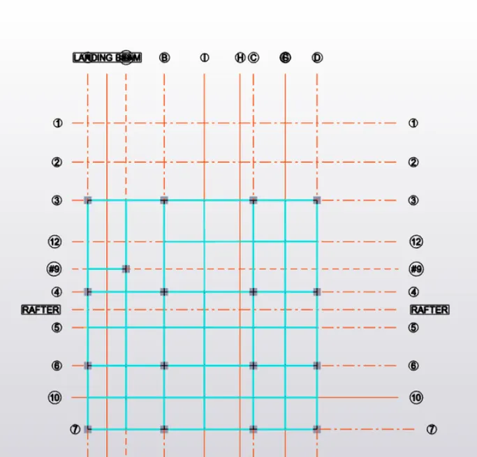
First Floor plan view

Top of roof beam view on the second floor plan
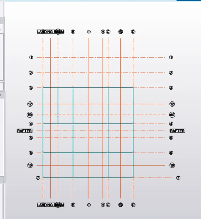
3D view
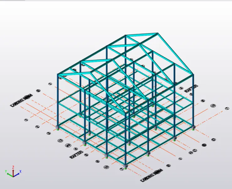
2. Create rafter beam on second floor as roof and moment frame action in one direction and add bracings at location.
- using Manage property sets>Member>Rafter to select the beam.
- Choosing the beam under Member>Manage property sets>Ridge
- Rafters and ridges are placed to create a 3D view.
- In Manage property sets>Member>Bracings, select Beam.
- X grid placement in Frame 3.
- X grid placement in Frame 7.