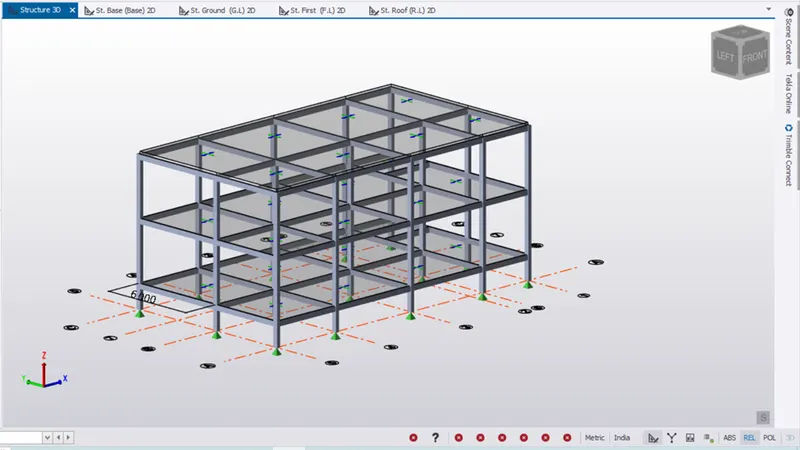
To Model a RC residential structure using TSD
1.Aim:
To Setup model for RC building design and based on following parameters for cover
|
MEMBERS |
IN CONTACT WITH GROUND |
ABOVE GROUND |
|
Column |
50mm |
40mm |
|
Beam |
30mm |
25mm |
|
Slab |
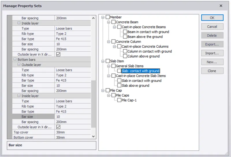
30mm |
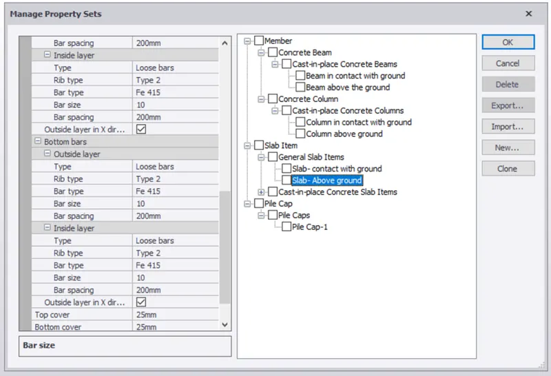
25mm |
|
Pile cap |
75mm |
|
|
Foundation |
50mm |
Procedure:
- Open new TSD file.
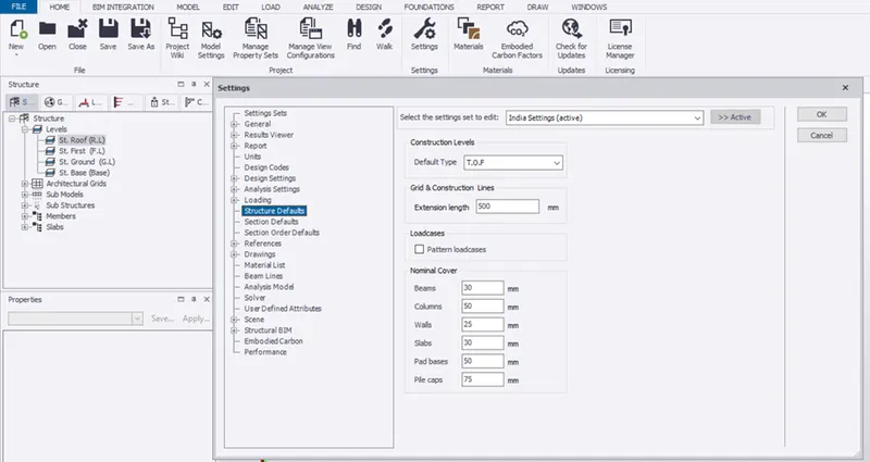
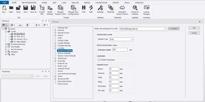
- Go to Home-> Settings -> Structural defaults
- For members in contact with ground:
- Give the following cover values.
- For members above the ground:
- Give the following cover values.
Result:
- Hence the covers are provided as mentioned above
2.Aim:
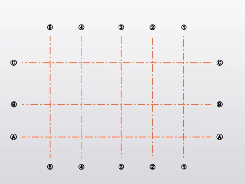
To model grids as per the attachment 2,2.1 and 2.2.
Procedure:
- Go to model -> grid line
- Pick the first vertical line as 1 and select the Quick parallel and draw the remaining grids.
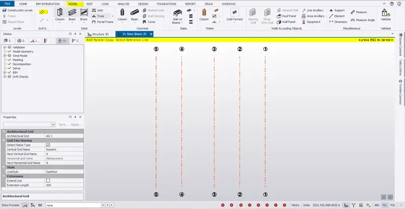
- Similarly draw the vertical grids.
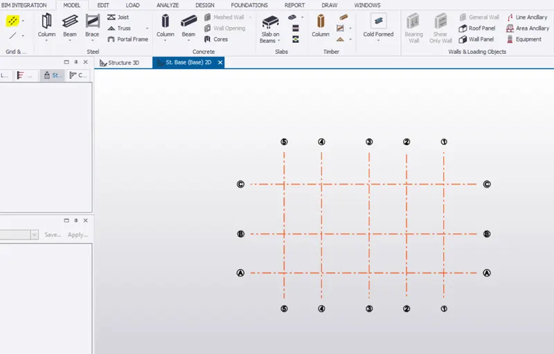
- Results:
- Hence the grid in drawn
3.Aim:
To study the layout and write a summary for general arrangement of the structure.
Procedure:
- RC building will be modeled, analyzed and designed in this and upcoming challenges.
- This structure consist of base level, ground level and first floor and roof level.
- It is a RC Office building with stairs and corridor
- The size of the building is 19.225mx10.700m on ground.
- The column and beam sizes about to be modeled are 225x300mm.
- Ground floor plan:
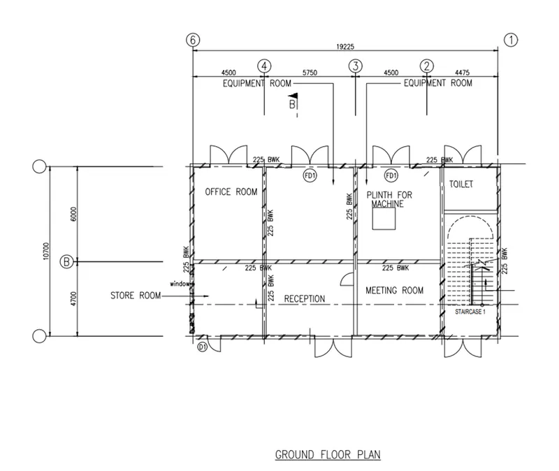
- The ground floor consist of 225 brick work wall.
- It has rooms like reception, meeting room, store room, office room ,toilet and staircase.
- First floor plan:
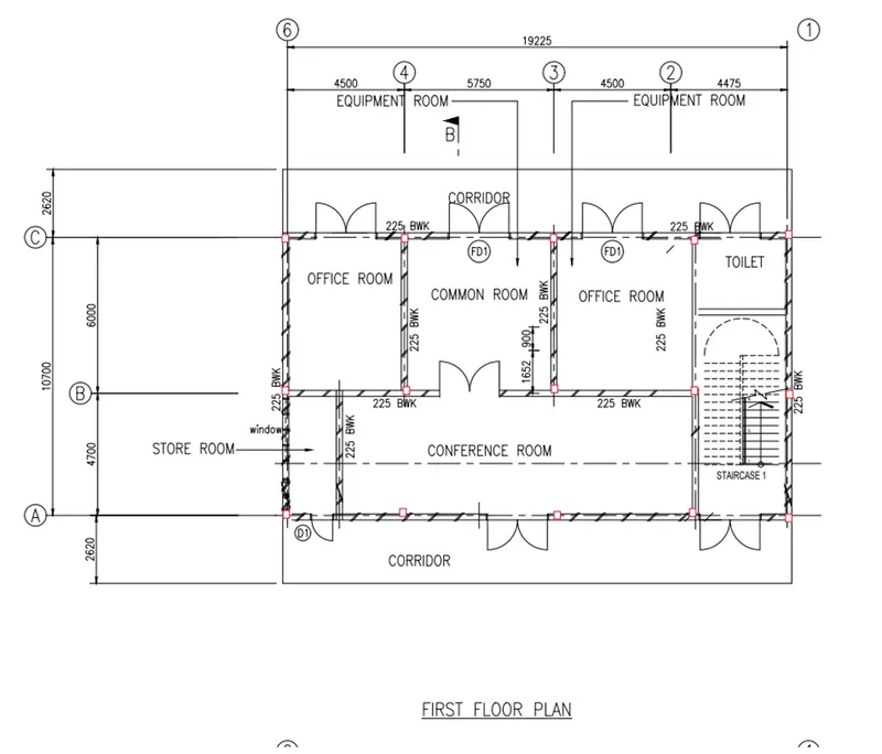
- The first floor also consist of 225 brick work wall.
- It consist of room likes conference room, 2 office rooms, common room, store room , toilet and staircase area.
- First floor also has 2 corridors on 2 sides of the buildings with 19.225x2.620mm dimension
- Roof plan:
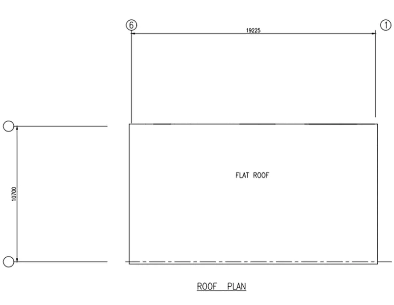
- It is a flat roof
Result:
- Hence the layout is shown and discussed above
4.Aim:
To model RC columns, beams and slabs as per the general arrangement.
Procedure:
- Open the new file in TSD
- Go to Home-> settings
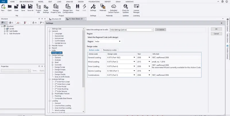
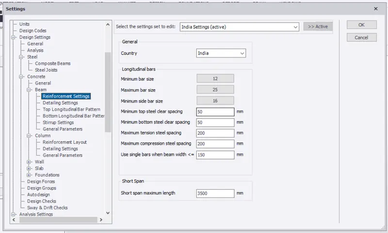
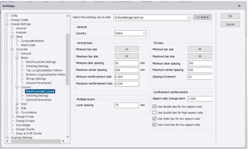
- Creating the members:
- Create the member with its appropriate property with its cover size.
- Beam in contact with ground:
- Go to Home -> manage property sets -> new -> member -> concrete beams.
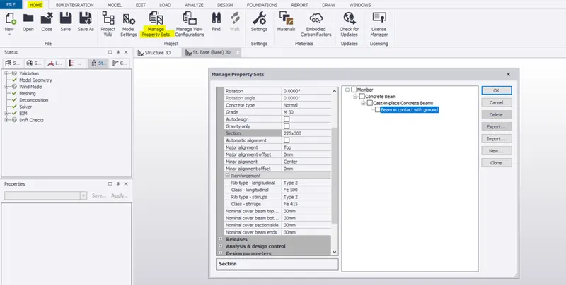
- Beam above the ground:
- Go to Home -> manage property sets -> new -> member -> concrete beams.
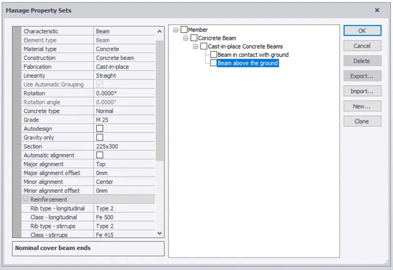
- Column below ground level:
- Go to Home -> manage property sets -> new -> member -> concrete column.
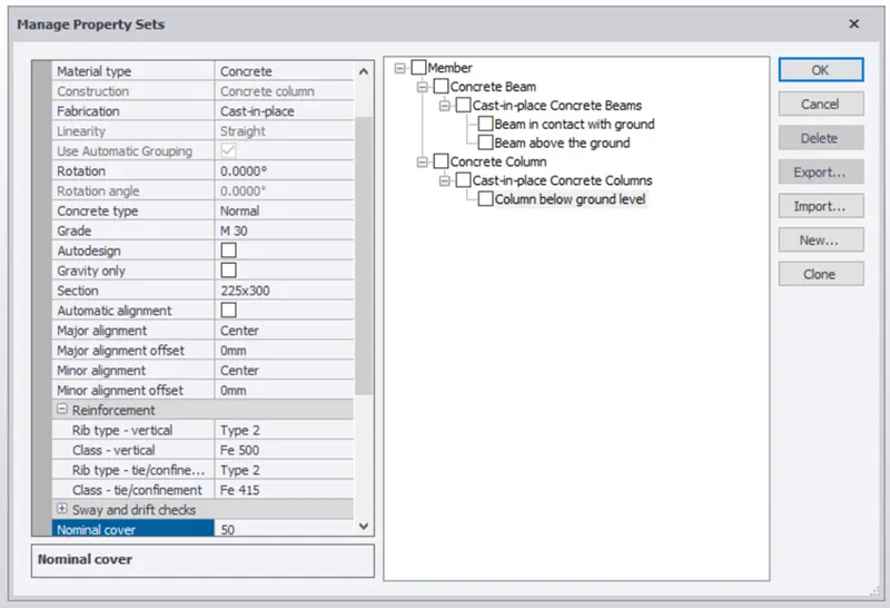
- Column above ground level:
- Go to Home -> manage property sets -> new -> member -> concrete column.
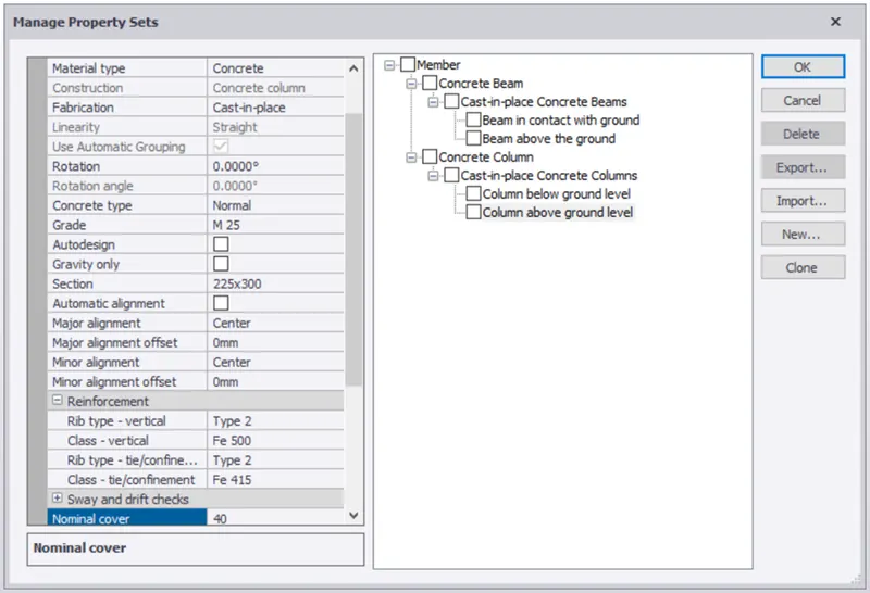
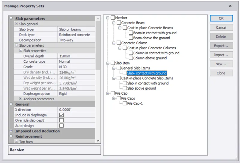
- Slab in contact with ground:
- Go to Home -> manage property sets -> new -> slab -> General slab items
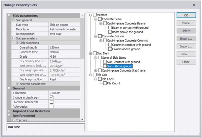
- Slab above ground:
- Go to Home -> manage property sets -> new -> slab -> General slab items
- Pile cape:
- Go to Home -> manage property sets -> new -> Pile cap
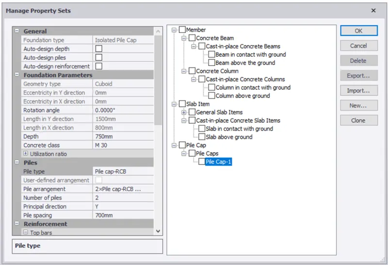
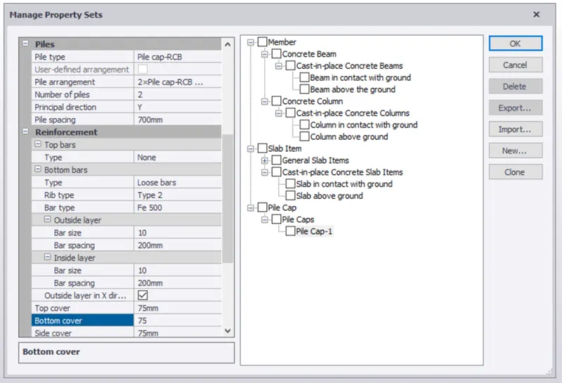
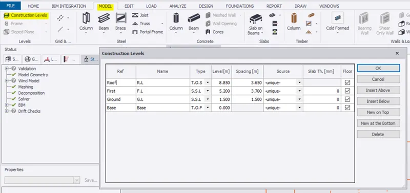
- Create construction level as shown below.
- Modeling column:
- Go to Base level-> concrete column and select the following property in the property window and select the grids
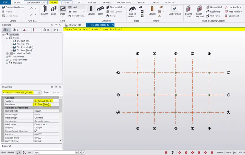
- Draw a grid 6 to create columns in between.
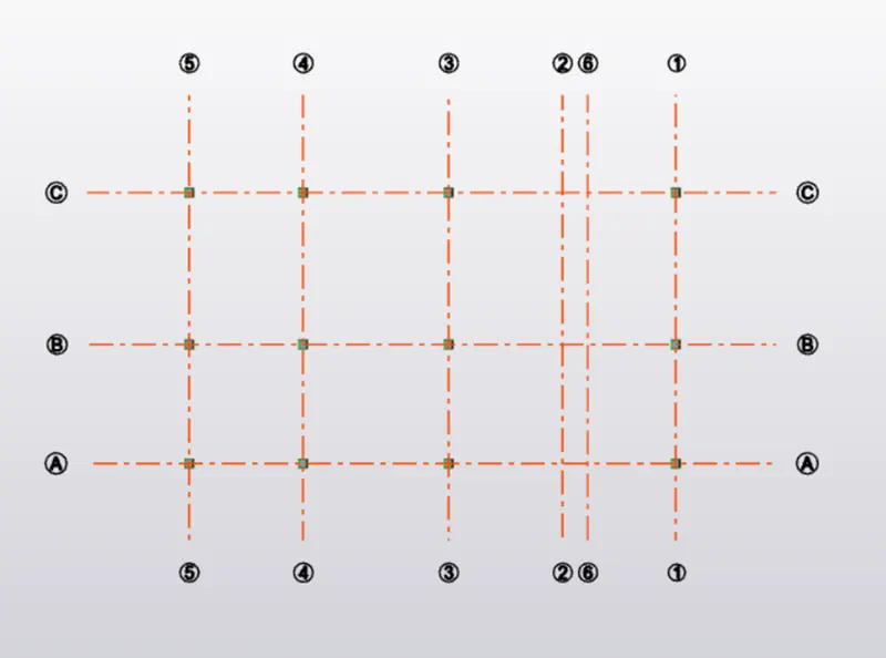
- Now pick the points.
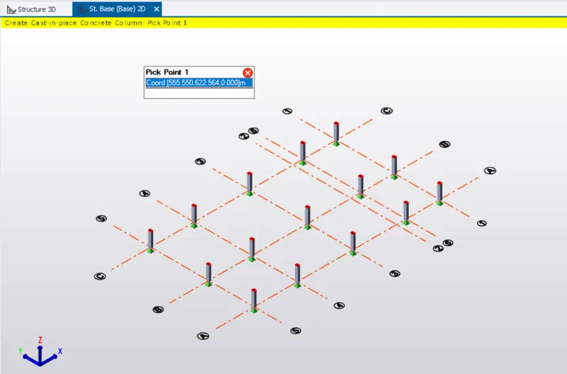
- Go to ground level and follow the same procedure.
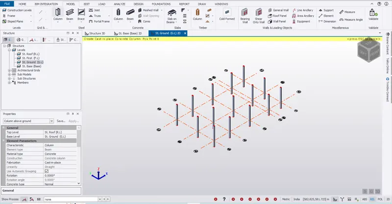
- Modeling beams:
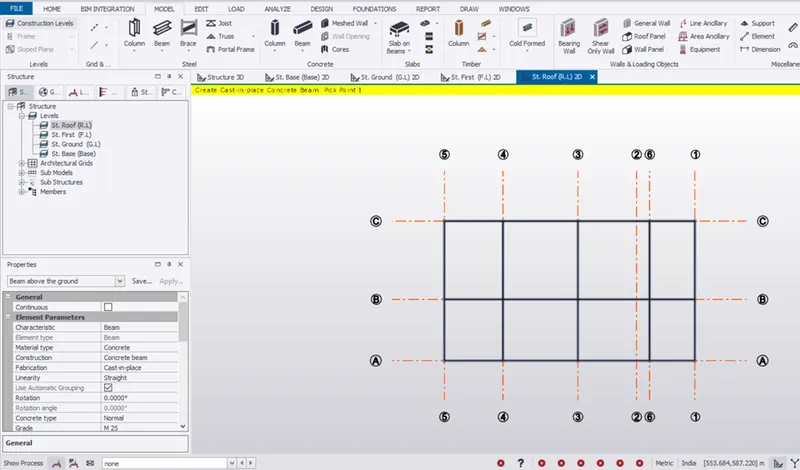
- Go to ground floor-> concrete beam and select the following property in the property window and select the columns to connect
- Create a grid D to create the beam near stairs.
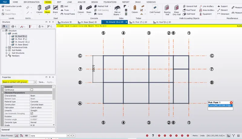
- Follow the same procedure on first floor
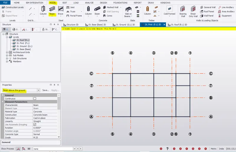
- Follow the same procedure on roof level.
- Modeling slab:
- Go to ground floor-> slab on beams and select the following property in the property window and click inside the beams
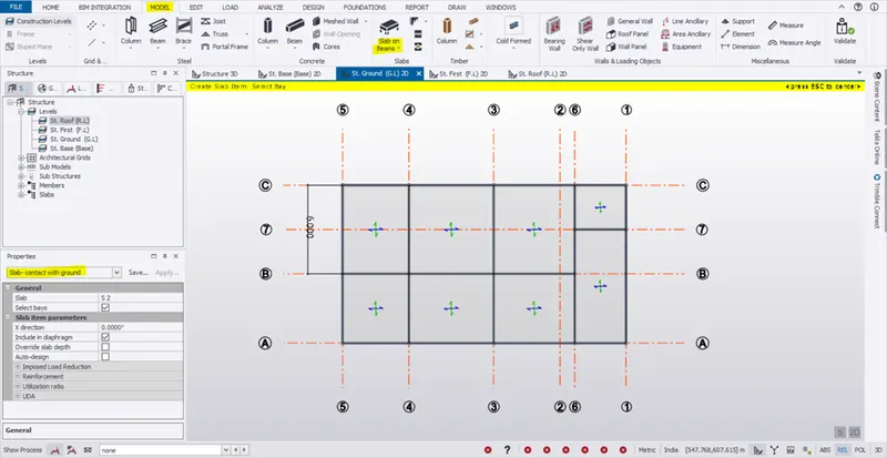
- On first floor,
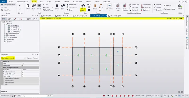
- On roof,
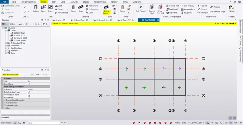
- Results:
- Hence the members are modelled.