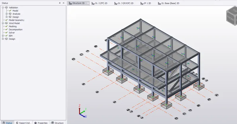
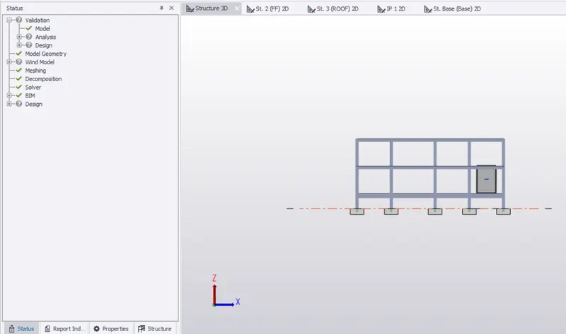
To Model a RC residential structure using TSD
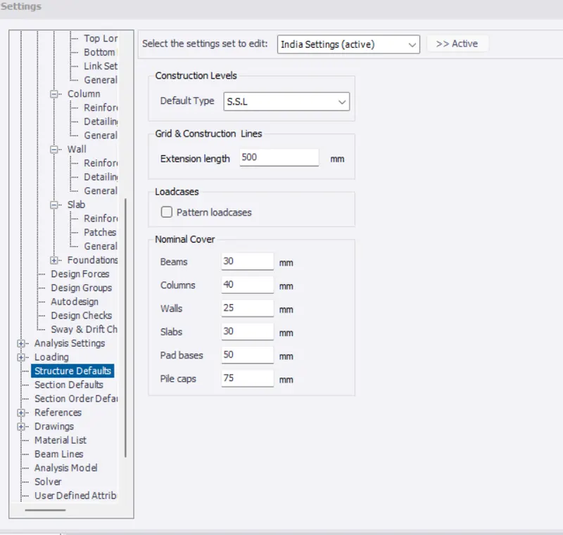
1. Setup model for RC building design and based on following parameters for cover
|
MEMBERS |
IN CONTACT WITH GROUND |
ABOVE GROUND |
|
Column |
50mm |
40mm |
|
Beam |
30mm |
25mm |
|
Slab |
30mm |
25mm |
|
Pilecap |
75mm |
|
|
Foundation |
50mm |
AIM : To create RC building design using Tekla structures
INTRODUCTION :
- Thickness of walls is 225 mm
- Slab thickness is taken as 125 mm
- Size of concrete column taken as 400x400 mm
- Size of concrete beam taken as 400x600 mm
- Size of stringer beam taken as 250x500 mm
PROCEDURE :
- Open new project in tekla structures
- Open settings and change settings to indian code
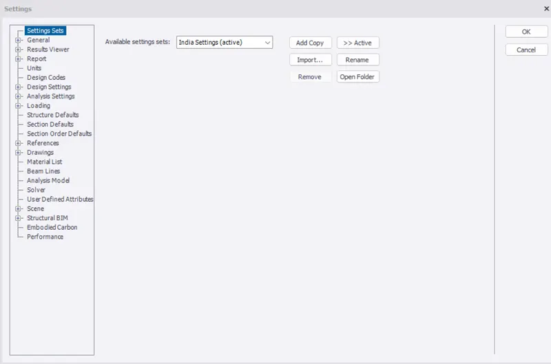
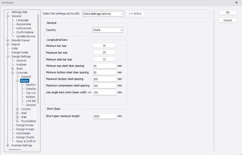
- Set beam details in "Design setting" as :
- 1. Reinforcement details
- Minimum bar size as 16mm and Maximum bar size as 25mm, Minimum side bar=12mm
- Minimum top steel clear spacing =50mm
- Minimum bottom steel clear spacing =50mm
- Maximum tension steel spacing = 200mm
- Maximum compression steel spacing = 200mm
- Use single bars when beam width <=150
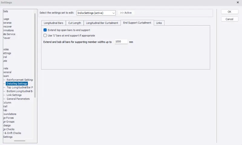
- 2. In Detailing settings of beam tick mark "Extend top span bars to end support" and select symmentrical in links
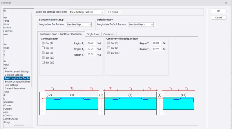
- 3. In Top Longitudinal bar set as "Standard top 1"
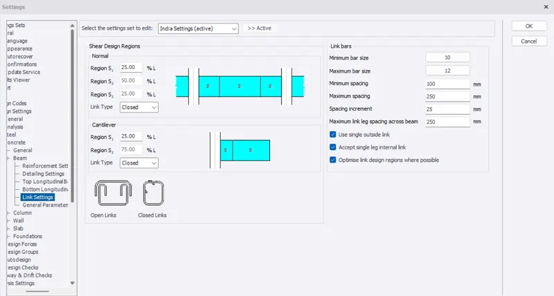
- In stirrup setup
- Minimum bar size 10mm
- Maximum bar size 12mm
- Minimum spacing 100mm
- Maximum spaing 250mm
- Spacing increment 25mm
- Maximum link leg spacing across beam 250mm
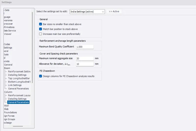
- Now set "Column settings"
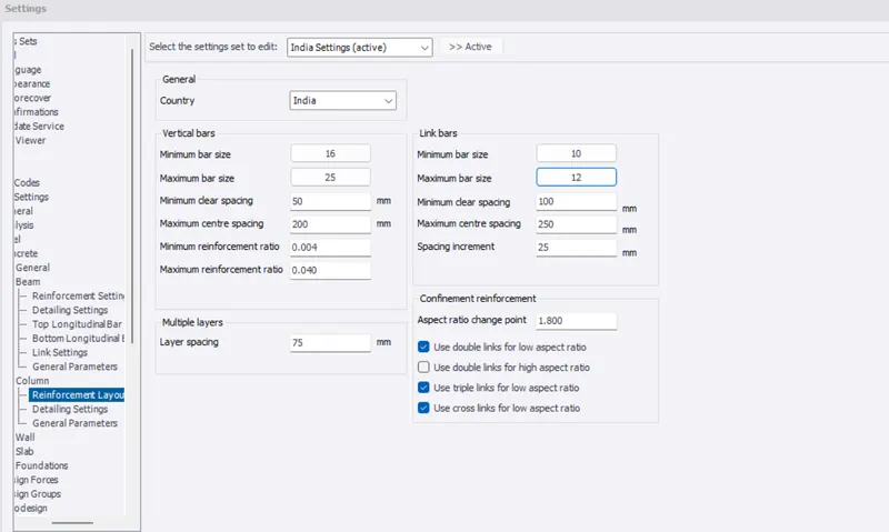
- 1. Reinforcement details
- In vertical bars :
- Minimum bar size = 16mm
- Maximum bar size = 25mm
- Minimum clear spacing = 50mm
- Maximum centre spacing = 200mm
- Minimum reinforcement = 0.004
- Maximum reinforcement ratio = 0.040
- Link bars
- Minimum bar size = 10mm
- Maximum bar size = 12mm
- Minimum clear spacing = 100mm
- Maximum clear spacing = 250mm
- Spacing increment = 25mm
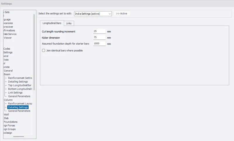
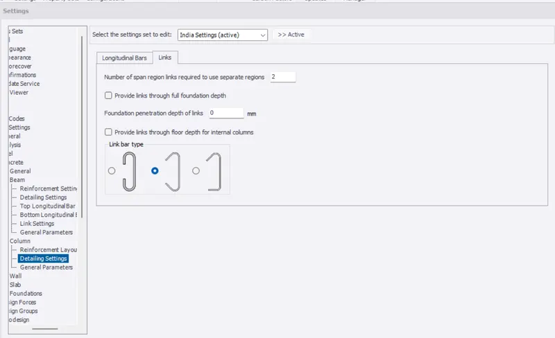
- 2. In Detailing settings check longitudinal bars and type of stirrups
- Similarly set wall reinforcement details as :
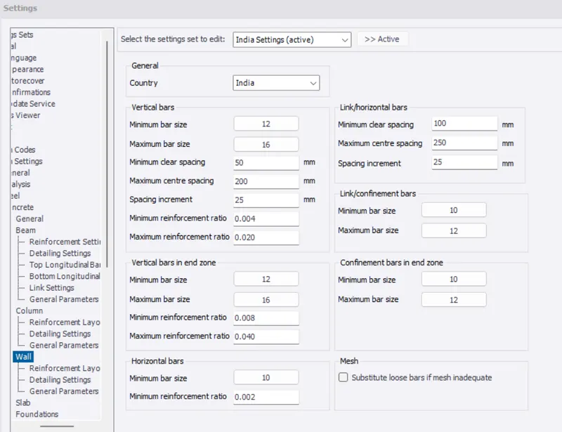
- 1. Reinforcement details
- In vertical bars :
- Minimum bar size = 12mm
- Maximum bar size = 16mm
- Minimum clear spacing = 50mm
- Maximum centre spacing = 200mm
- Minimum reinforcement = 0.004
- Maximum reinforcement ratio = 0.040
- Vertical bars end zone
- Minimum bar size = 12mm
- Maximum bar size = 16 mm
- Minimum reinforcement ratio = 0.008
- Maximum reinforcement ratio = 0.040
- Horizontal bars
- Minimum bar size =10
- Minimum reinforcement ratio = 0.002
- Link/Horizontal bars
- Minimum clear spacing = 100mm
- Maximum centre spacing = 250mm
- Spacing increment = 25mm
- Link/Confinement bars
- Minimum bar size = 10mm
- Maximum bar size = 12mm
- Confinement bars in end zone
- Minimum bar size = 10mm
- Maximum bar size = 12mm
- Change slab settings as :
- Maximum principle bar spacing distance x slab depth = 150x2
- Maximum secondary bar spacing distance x slab depth = 250x3
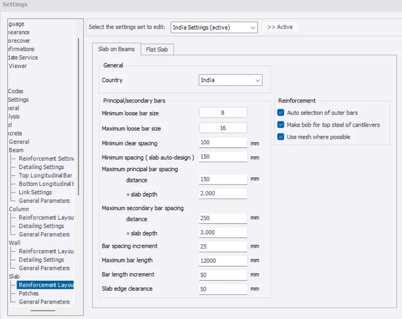
- Check structure defaults
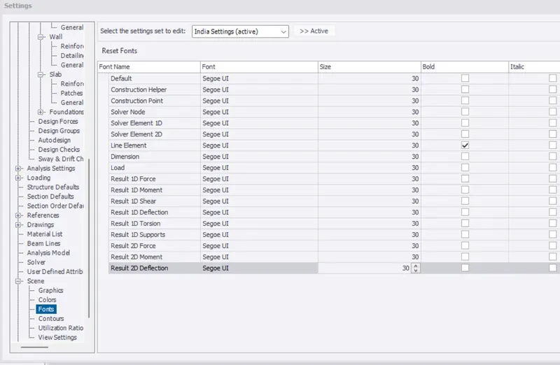
- Set Font sizes to 30
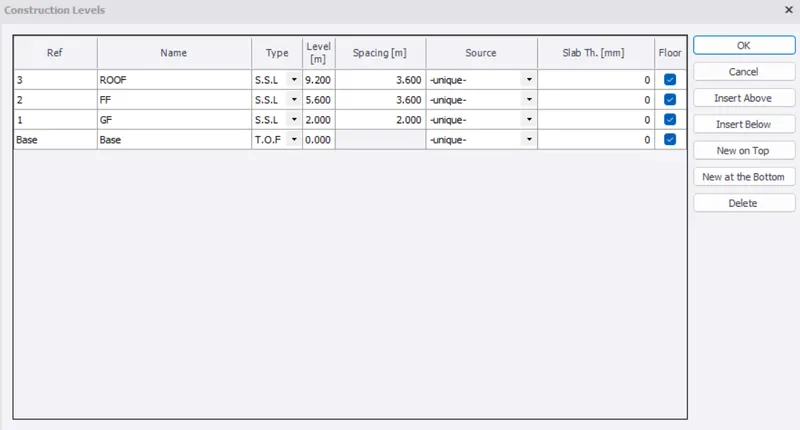
- Set construction levels which contains ground floor, first floor and roof with spacing 3.6m
- Foundation settings
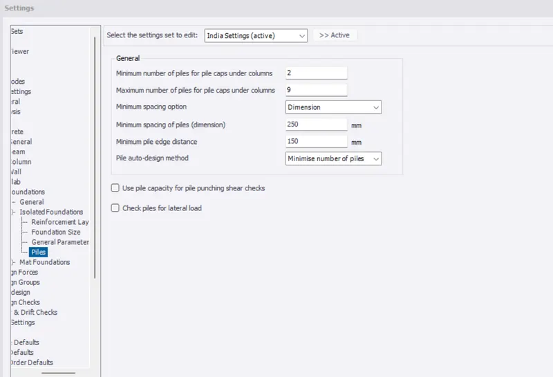
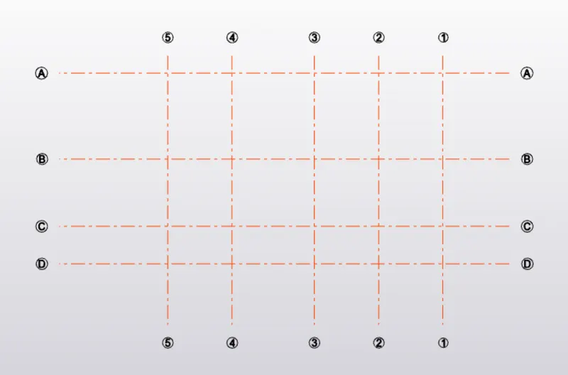
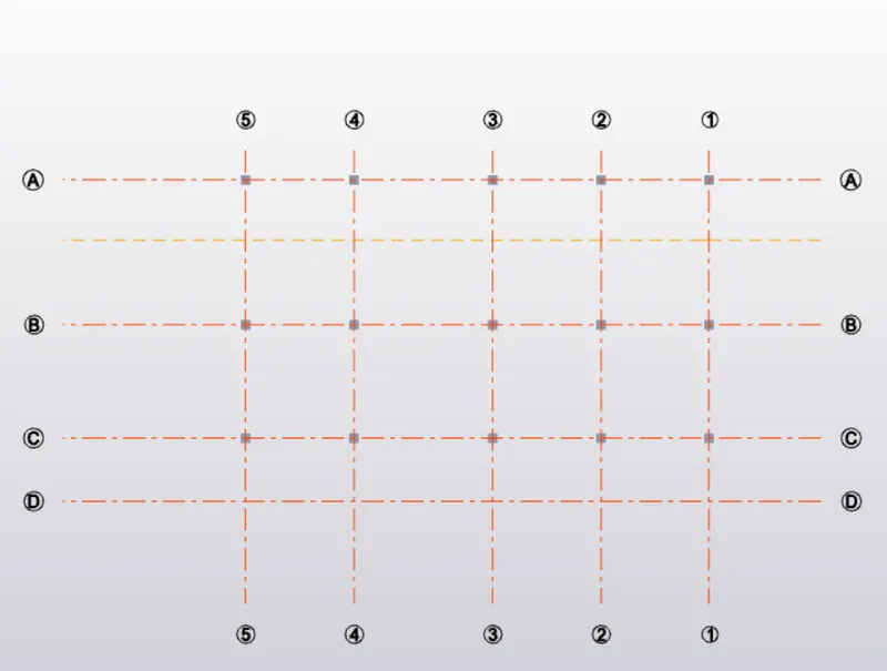
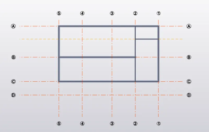
- Now draw grids lines according to the dimensions given in plan :
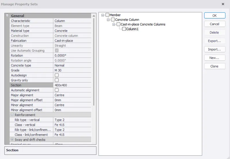
- Set column, beam properties
- Column = 400x400 size with M30 grade
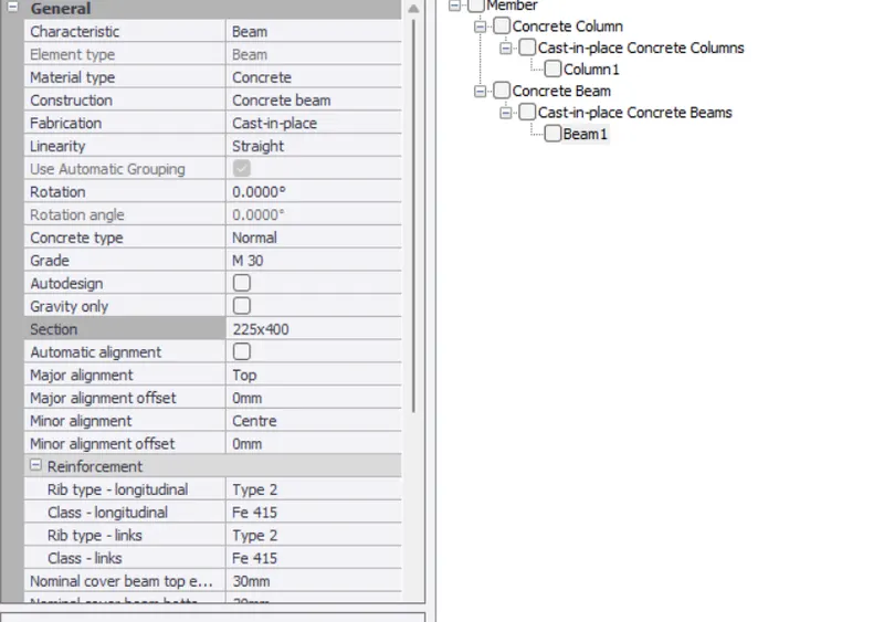
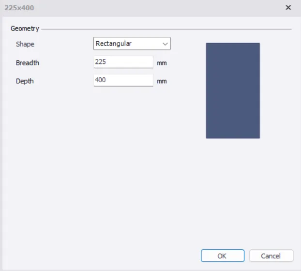
- Beam = 225x400mm and M30 grade
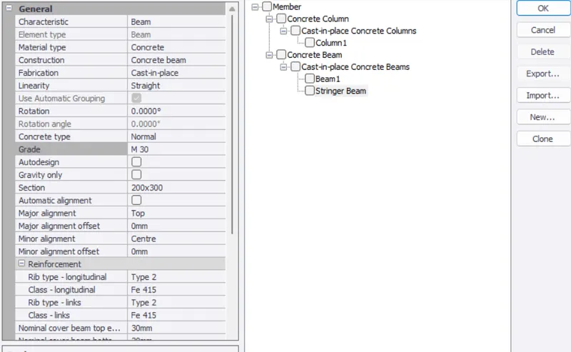
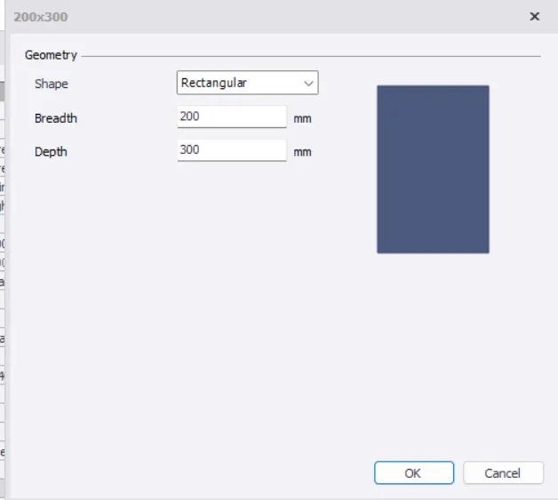
- Stringer beam = 200x300mm with M30 grade
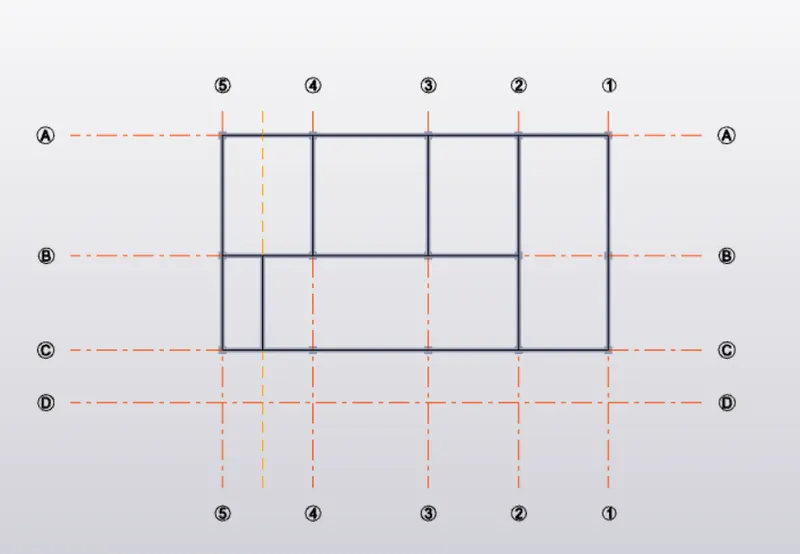
- Place columns (From base to roof) and beams in Ground floor and First floor
- Ground floor
- First floor
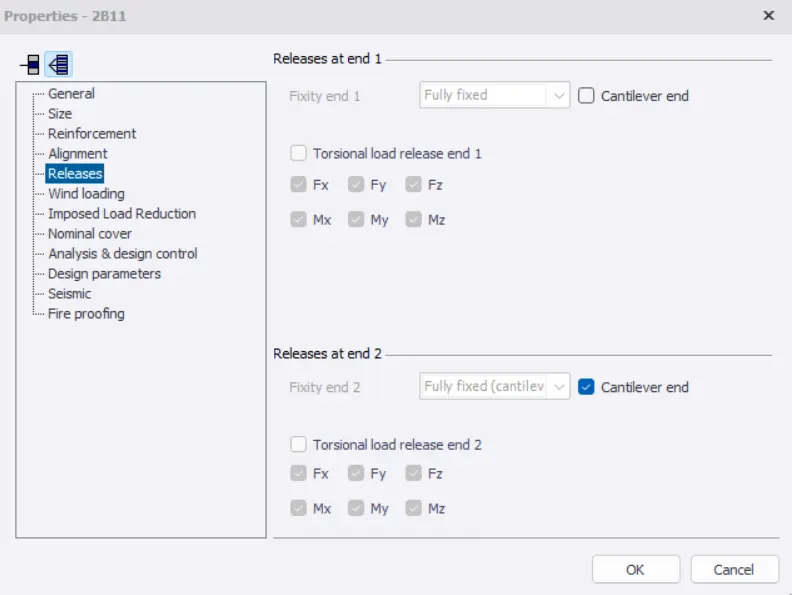
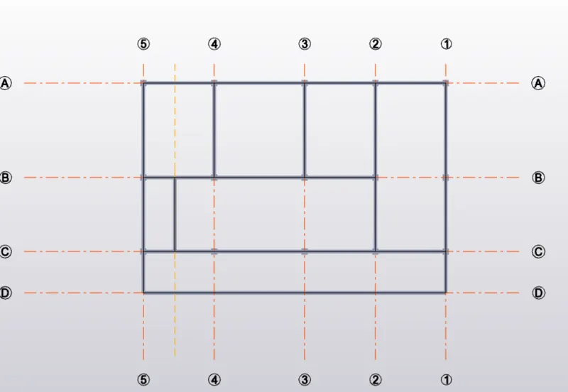
- Draw beams in corridor First floor and make those beams as cantilever beam by changing properties
- Draw beams in roof level
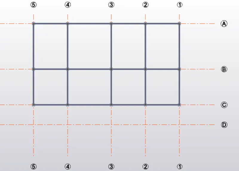
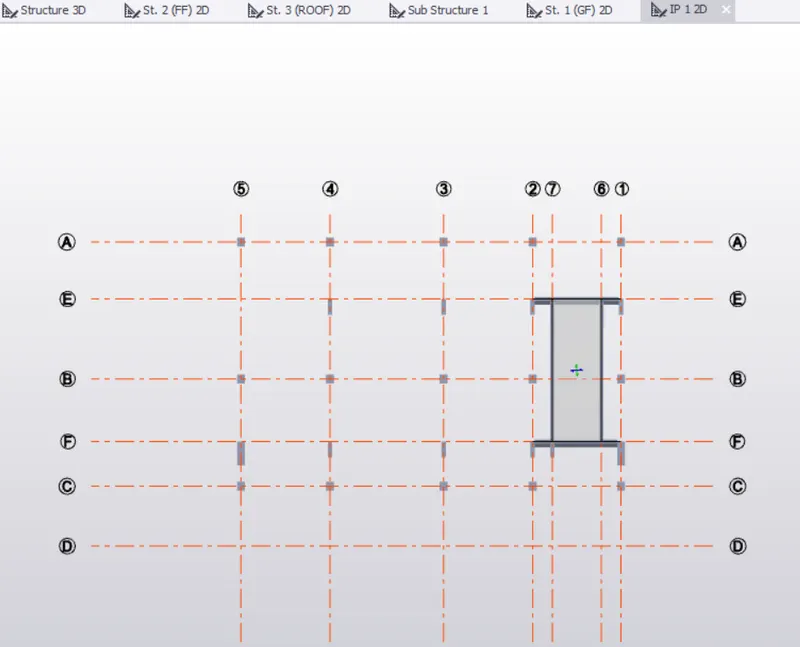
- Now draw stringer beam for staircase
- To add staircase
- Select beams, columns around staircase
- Right click on members and select add to substructure
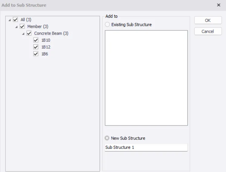
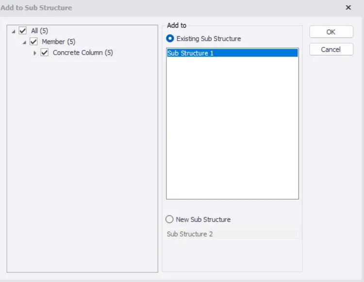
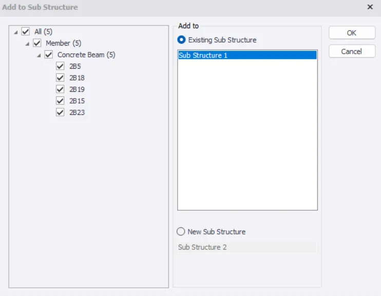
- Open substructure from properties panel
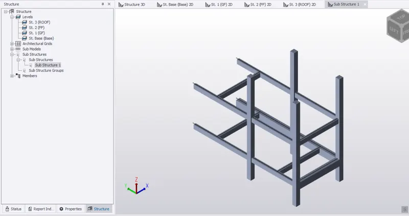
- Click on sloped plane and draw stringer beams for the staircase
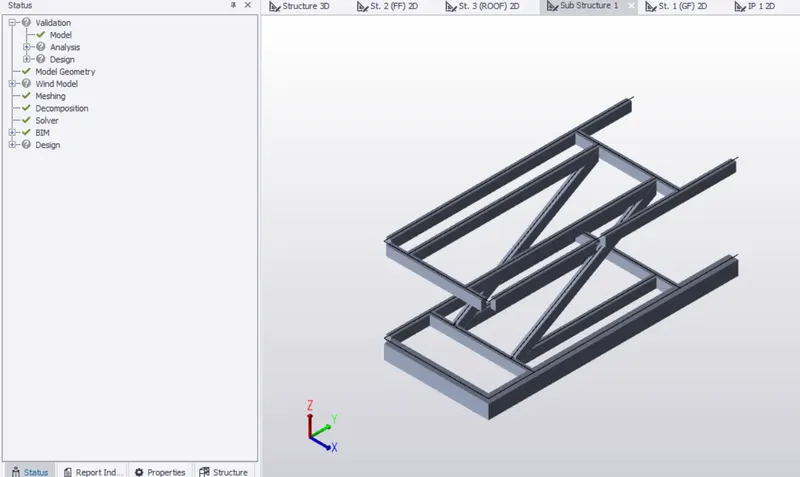
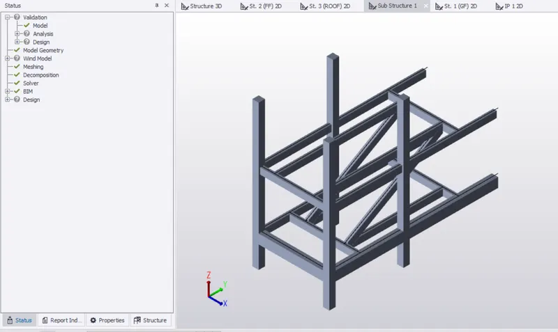
- Draw slabs on groundfloor, first floor, roof floor with 125mm thickness and staircase slab 100mm thickness
- Ground floor
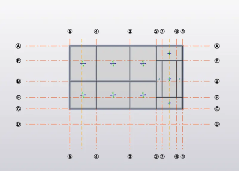
- First floor
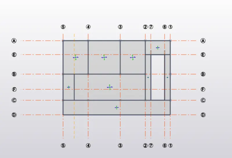
- Roof floor
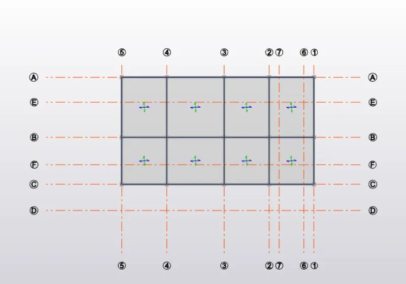
- Validate the model
RESULTS :