TO DEVELOP AN ADAS FEATURE FOR COLLISION MITIGATION BRAKING SYSTEM (CMBS) USING MATLAB SIMULINK
OBJECTIVE
TO DEVELOP A SIMULINK MODEL FOR ONE OF THE ADAS FEATURE OF COLLISION MITIGATION BRAKING SYSTEM (CMBS)
ABSTRACT
In this project we need to develop a model based design using Simulink for the feature that the CMBS should get deactivated while the vehicle is moving in reverse direction/reverse gear. The Simulink model should detect the direction of the vehicle. The CMBS should get activated once the vehicle is moving forward at speeds above 15km/h.
INTRODUCTION OF CMBS
What is CMBS?
Collision Mitigation Brake System (CMBS) is a radar‐based autonomous emergency braking system. At speeds above 15km/h, moving and stationary vehicles are detected along a path some 100m ahead of the vehicle.
It can assist you when there is a possibility of your vehicle colliding with a vehicle or a pedestrian detected in front of yours. The system can give you visual, audible, and tactile alerts when a potential collision is determined, and reduce your vehicle speed to help minimize collision severity when a collision is deemed unavoidable. When a potential collision with a detected oncoming vehicle is determined, the system also alerts you with rapid vibrations on the steering wheel.
Features of CMBS
Collision Mitigation Braking System (CMBS) can assist you when there is a possibility of your vehicle colliding with a vehicle or a pedestrian detected in front of yours. The CMBS is designed to alert you when a potential collision is determined, as well as to reduce your vehicle speed to help minimize collision severity when a collision is deemed unavoidable.
Alert Stages
The system has three alert stages for a possible collision. Depending on the circumstances or CMBS settings, CMBS may not go through all of the stages before initiating the last stage.
Stage 1: Visual and audible warning, steering wheel vibrations
Stage 2: Visual and audible warning, light brake application
Stage 3: Visual and audible warning, strong brake application
Changing Settings
- From the HOME screen, select Settings.
- Select Vehicle. The vehicle must be in Park (P). Beep Steering vibrations
- Select Forward Collision Warning Distance.
- Select Long, Normal, or Short.
- Press BACK to exit the menu. Turning CMBS On or Off Press and hold the CMBS OFF button.
A beep sounds and a message appears in the MID. The CMBS indicator appears when the system is off. Important Safety Reminder CMBS is designed to reduce the severity of an unavoidable collision. It does not prevent collisions nor stop the vehicle automatically. It is still your responsibility to operate the brake pedal and steering wheel appropriately according to the driving conditions.
PROCEDURE
- Requirement Analysis is the first step for developing any model. This consist of a function requirement and feature description. In the requirement following points are considered for developing the model
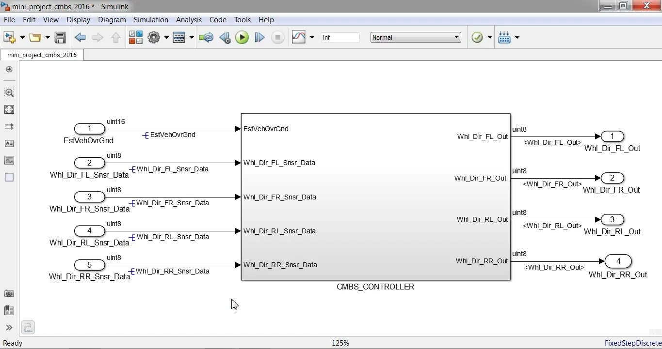
Fig. CMBS CONTROLLER
- Collision mitigation braking system (CMBS) should start its working only when the vehicle speed is attained to 15Km/hr.
- Brake system on vehicles equipped with CMBS and a manual transmission should communicate with the wheel direction for at least 1 wheel via CAN signal, Whl_Dir_xx.
- If a (fault) is unable to detect accurate vehicle direction, Whl_Dir_xx should be set to ‘Failed’. In case of normal condition it should report ’Unknown’ (0kmph if direction detection is temporary not accurately available)
- If a directional wheel speed sensor is not installed on a given wheel, the Whl_Dir_xx is set to ‘Unknown’
- Vehicle speed is compared with calibration data that states the direction detection is not accurate.
- If the vehicle speed is greater than calibration data, FAULT will be detected at the wheel direction detection
- Fault data pf vehicle wheel sensor is compared against the vehicle wheel sensor data & the error which compares with the direction of the wheel
- When no fault is detected it takes sensor data or else error data will be calculated. This calculation remains same across all wheels
- Model development is the next step after the requirement analysis using the information from it the model will be developed. Initially we need to create a controller subsystem in which all the input and output ports should be available.
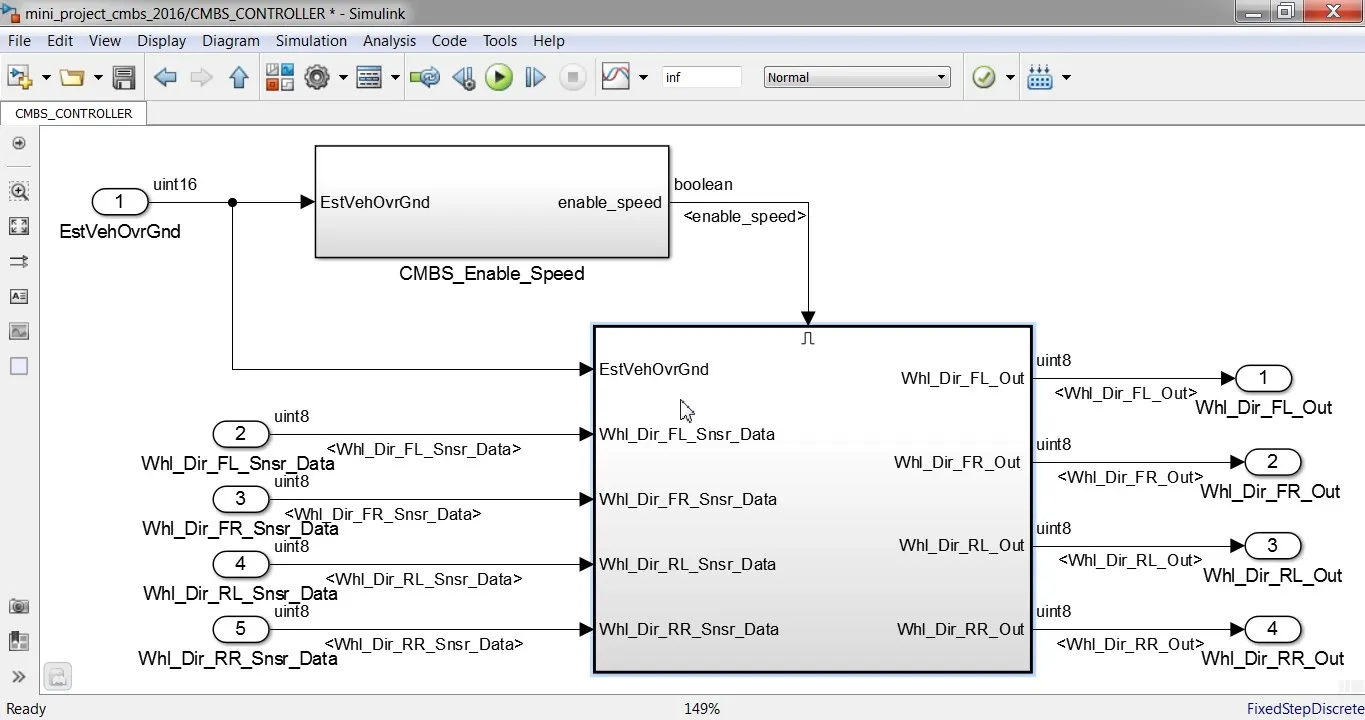
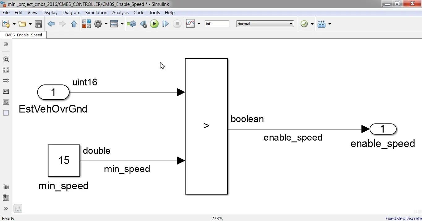
CMBS ENABLE SUBSYSTEM
- The input port for the model are:
- Vehicle speed data - EstVehOvrGrnd
- Front right wheel direction sensor – Whl_Dir_FR_Snsr_Data
- Front left wheel direction sensor – Whl_Dir_FL_Snsr_Data
- Rear right wheel direction sensor – Whl_Dir_RR_Snsr_Data
- Rear left wheel direction sensor – Whl_Dir_RL_Snsr_Data
- The output ports for the model are:
- Front right wheel direction data – Whl_Dir_FR_Out
- Front left wheel direction data – Whl_Dir_FL_Out
- Rear right wheel direction data – Whl_Dir_RR_Out
- Rear left wheel direction data – Whl_Dir_RL_Out
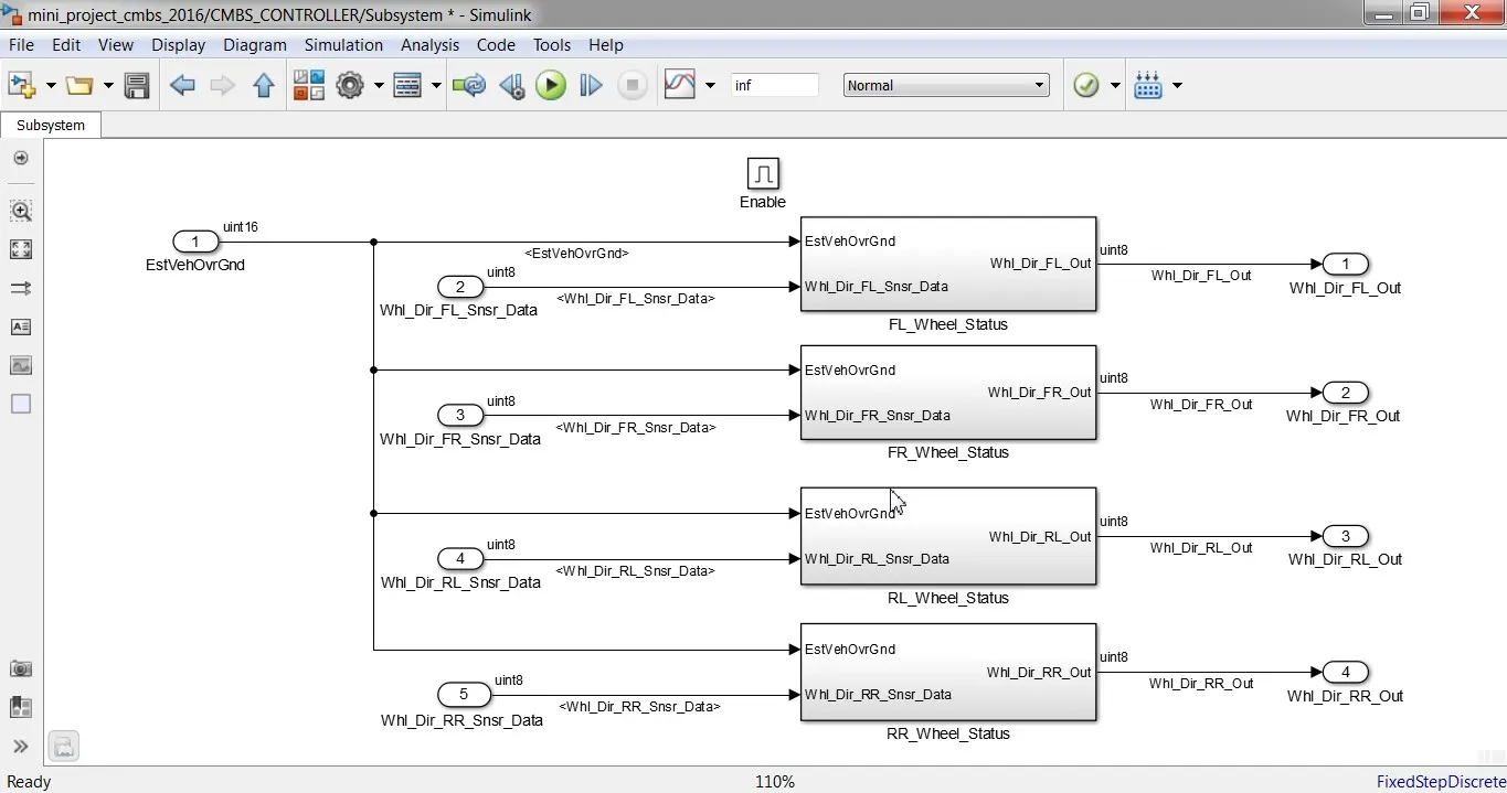
Fig. CMBS WHEEL STATUS
- Inside the CMBS _Controller subsystem, another enabled subsystem is created which will be enabled if the vehicle speed be more than the threshold speed which 15km/hr. Input speed ‘EstVehOvrGrnd’ will be compared with the constant block with value 15 using relational operator.
- Inside the enabled subsystem, there will be 4 separate subsystem for each wheel, and each subsystem provides the wheel direction as the output. Each of the subsystem receive the input data as the input vehicle speed and their respective wheel sensor data.
- Inside the subsystem for ‘FL_Whl__Status’ as per our requirement the vehicle input speed is compared with the calibration value ‘K_Vehspd_dirdetect’ using the relational operator, output of this block is given to the switch block. If result of the comparison is 1 i.e when the vehicle speed is greater than calibration value the direction of the wheel is set to FAILED. FAIL_DIR will go further else the UNKNWN_DIR will go further as an input to another switch block. Output of the switch is again used as the input for another switch block.
- The switch will be triggered by the detection of sensor fault.
- If the sensor data has the fault then the error data generated from previous switch goes as the output, if the sensor data do not have fault then wheel sensor data goes out of the switch as wheel direction output signal.
- Similar arrangement of blocks for each wheel is created except the wheel sensor data is separate for each wheel.
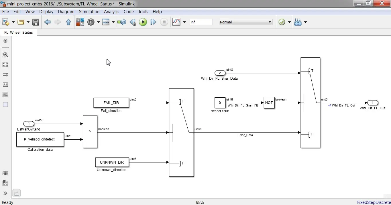
Fig. FRONT LEFT WHEEL STATUS
- Simulink Data Dictionary is used to describe all the signals used while designing the model. A new SLDD is created and linked with the model created for CMBS feature. All the signal properties are edited according to the requirement. Signal properties such as Data type, storage, maximum value, minimum value etc. needs to be defined. Initially we need to add Alias type to describe all data types, then Simulink parameter signals are added. Lastly all the signals used in the model are specified with the properties given in the requirement data.
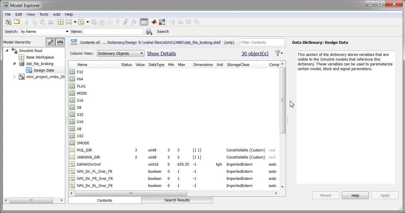 Fig. SLDD
 - Signal resolving is the next important task as the signals are specified in SLDD. If the signals are originating from the block then these signal should be marked as Simulink signal object and if these signals goes from each subsystem and then block, it should be marked as propagated signal in its further process.
- Model Update is carried out after resolving all the input and output signal, the model is updated using update option under the Modelling Tab. Ctrl +D is the shortcut for carrying out model update. If no errors are found during model update, it means there will not be any error while the model will run also no errors during code generation.
- Configuration parameter is updated once the model don’t show any error, model setting option is available under Modelling Tab
- Model Advisor Check is carried out for the parameters used in the model. Model advisor check is under the Modelling Tab. All the warnings and the errors were resolved and the final report is generated.
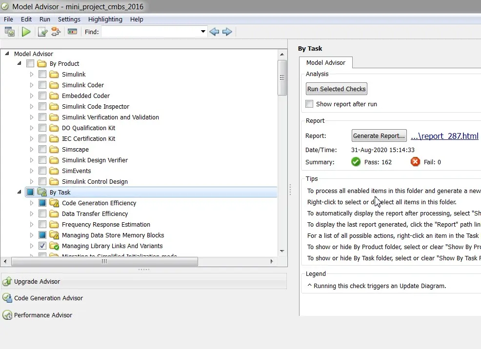
Fig. MODEL ADVISOR CHECKS
The Code is generated of the CMBS model. The shortcut for code generation is Ctrl+B.
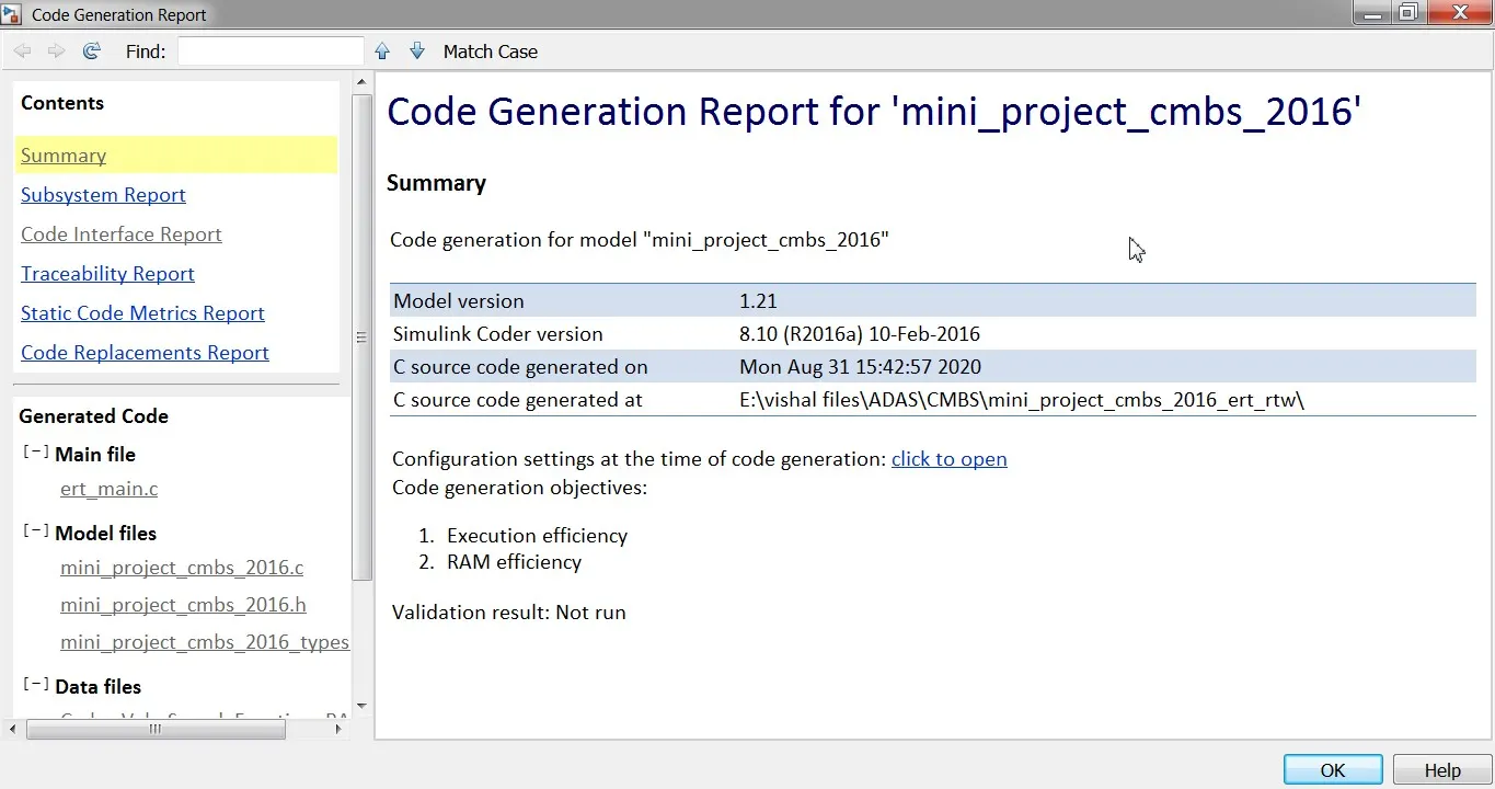
Fig. CODE GENERATION REPORT
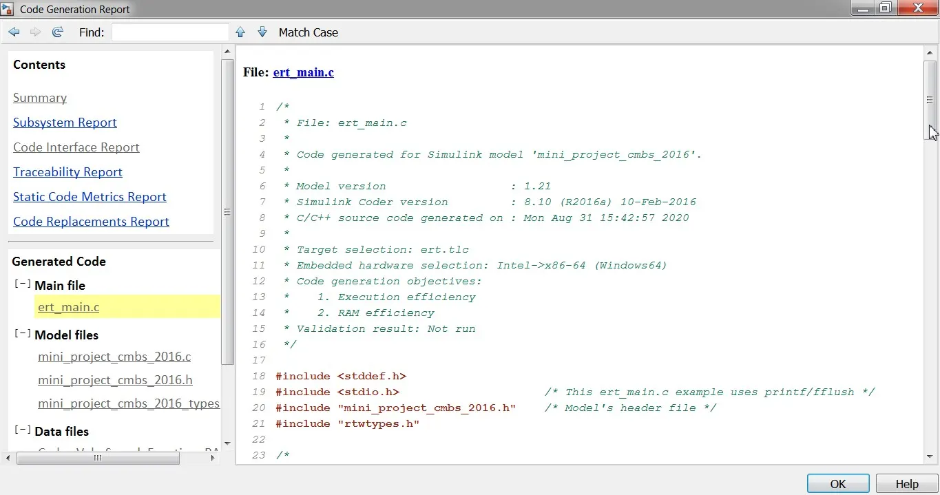 Fig. C-CODE
RESULTS
- The output of the model developed in Simulink is the information regarding direction of each wheel.
- Finally the Code is successfully generated for the CMBS model. The shortcut for code generation is Ctrl+B. After successful code generation, C-code is generated for the Model CMBS developed using Simulink.
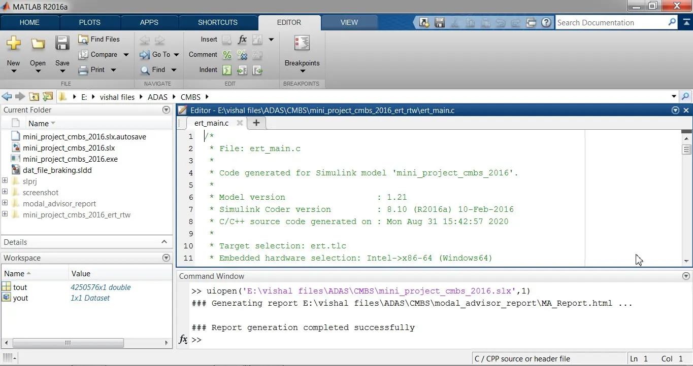
Fig. C-CODE GENERATED SUCCESSFULLY