To calculate the dead , live and wind load for RC residential structure and to apply them using TSD
1Q. Calculate dead load in design report based on IS Code and apply dead load on the mode
- Finishes of 50mm
- Slab thickness as per the design
- Brick eall load
- Roofing load
Answer:
Dead Weight:
- Completes the load for a thickness of 0.05x24 = 1.2 KN/m^2 (50 mm)
- The software models slab load as equal to slab dead load.
- One brickwall's loading when plaster is 155 mm thick.
- It is established that the weight of a brick is 20 KN/m^3.
Floor Height
From first floor to rooftop: 3 meters
For the brick wall loading, compute 0.155x3x20 = 9.3 KN/m.
Plaster thickness plus brick wall loads equals 230 mm for two brick walls.
Brick weight is known to be 20 KN/m^3.
height of the floor
From first floor to rooftop: 3 meters
The brick wall loading is now calculated as follows: 0.230x3x20= 13.8 KN/m.
Roof loading:
1.5 KN/m^2 is the dead load calculated by adding the slab weight and any other minor loading, such as water proofing.
Dead Load:
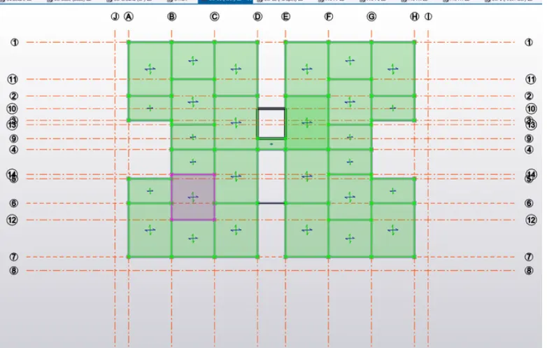
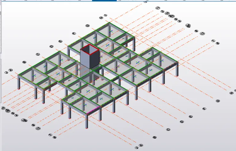
An area load of 1.2 KN/m^2 is imposed from the ground floor to the tenth floor as the finishing load.
Wall load for interior walls with a 155mm thickness requires the application of 9.3 KN/m as the entire UDL from the ground floor to the tenth storey.
Wall load for exterior walls with a 230 mm thickness, or 13.8 KN/m, must be applied as the entire UDL from the ground floor to the tenth storey.
Dead load, or the finishing load applied to the roof area, is 1.2 KN/m^2.
Full UDL applies a parapet wall load of 0.230x20x1.5=1.3 KN/m.
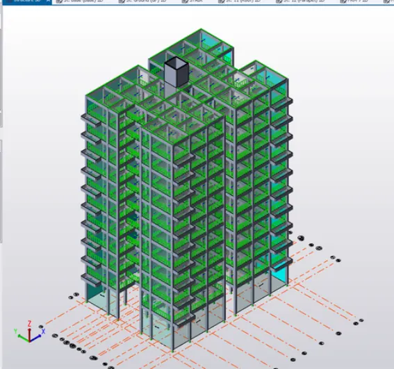
3D View:
2Q. Calculate live load in design report as per IS code and apply dead load on the model.
Answer:
Live load consideration for residential buildings in accordance with IS 875 part 2 table 1
The accommodations listed in the plan are
Bedroom: 2 KN/m^2.
Dining = 2 KN/m^2
Room Pooja = 2 KN/m^2
Kitchen: 2 KN/m^2.
Toilets: 2 KN/m^2.
Storage space: 3 KN/m^2.
Step example: 3 KN/m^2
balconies = 3 KN/m^2
Drawing room = 3 KN/m^2
For the store room, a live load of 3 KN/m^2 is applied.
Every other room has a live load of 2 KN/m^2.
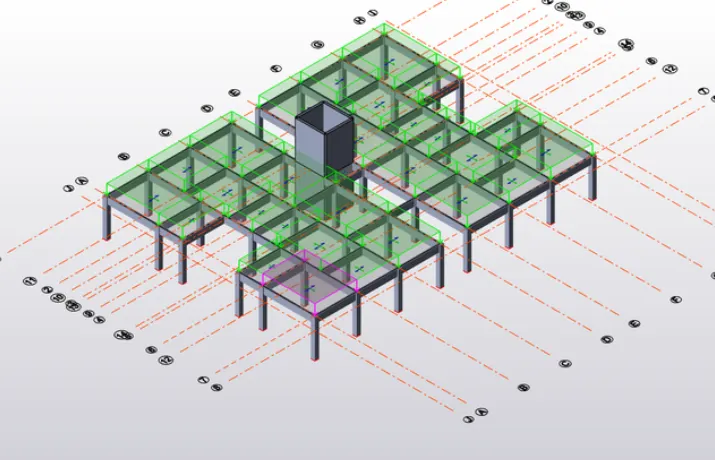
Live load of every floor in 3D, ranging from the first to the tenth
For the building, an area load of 0.3 KN/m^2 is applied from the first floor to the tenth floor.
The building's area load is set at 10 KN/m^2, with the service load applied at roof level.
3Q. Generate manual wind loading in the design report as per IS code as the following inputs.
- Basic wind speed = 50m/s
- Terrain category 2
Answer:
Wind load calculation:
Manual |
|
| Wind Load Calculation | |
| AS per IS 875 Part 3 | |
| Basic wind speed(Vb) | 47m/s |
| (From Annexure A Clause 6.2 of IS 1893 Part 3) | |
| Probable Design Life of structure | 50 years |
| Terrian Category | 2 |
| Class of the Structure | A |
| Horizontal Dimension of structure(Greater)I | 29.36 |
| Horizontal Dimension of structure(Lesser)w | 21.24 |
| Eaves level Height of structure | 41.6 |
| Width of Frame 1 between the Grids | 6 |
| Ratio for Wall and Roof Coefficients Wall | 11w h/w |
| wall h/w | 1.37 |
| wall I/w | 1.94 |
| Roof h/w | 0.94 |
Calculations:
Topography Factor k3 From Clause 6.3.3 1 Risk Coefficient kl From Table 1 1
Height in m up to 10 m
Terrian Height factor k2 = 1
Important Factor for Cyclonic Region k4 = 1.15
Design wind Speed Vz = Vb*kl"k2" k4 = 47 m/s
Design Wind Pressure Pz Vz^2 = 1325.4N/m
1.94 = Roof Angle alpha Internal Pressure Coefficient Internal Pressure Coefficient = 16 deg
0.5 (up to 20% opening) -0.5 (up to 20% opening)
Wall Loading Calculation Wind Direction = +Y WIND ANGLE = @90deg
| wall Load Calculation | (Applied in Global Y) | |
| Wind Direction = +X | ||
| For Face A & B | Cpi+ | Cpi- |
| Height at Different Level = | up to 10 m | up to 10 m |
| External pressure coefficient Cpe | -0.8 | -0.8 |
| Internal pressure coefficient Cpi | 0.5 | -0.5 |
| Net pressure coefficient Cp | -1.3 | -0.3 |
| Design wind pressure for wall | 1.33 | 1.33 |
| Loading to be applied on the wall in KN/m2 | -1.72 | -0.4 |
| After application of factor 1.05 in KN/m2 | -1.81 | -0.42 |
| After application of factor 1.07 in KN/m2 | -1.89 | -0.44 |
| After application of factor 1.12 in KN/m2 | -1.93 | -0.45 |
| After application of factor 1.17 in KN/m2 | -2.02 | -0.47 |
| wall Load Calculation | ||
| Wind Direction = +X | ||
| For Face C | Cpi+ | Cpi- |
| Height at Different Level = | up to 10 m | up to 10 m |
| External pressure coefficient Cpe | 0.8 | 0.8 |
| Internal pressure coefficient Cpi | 0.5 | -0.5 |
| Net pressure coefficient Cp | 0.3 | 1.3 |
| Design wind pressure for wall | 1.33 | 1.33 |
| Loading to be applied on the wall in KN/m2 | 0.40 | 1.72 |
| After application of factor 1.05 in KN/m2 | 0.42 | 1.81 |
| After application of factor 1.07 in KN/m2 | 0.44 | 1.89 |
| After application of factor 1.12 in KN/m2 | 0.45 | 1.93 |
| After application of factor 1.17 in KN/m2 | 0.47 | 2.02 |
| wall Load Calculation | ||
| Wind Direction = +X | ||
| For Face D | Cpi+ | Cpi- |
| Height at Different Level = | up to 10 m | up to 10 m |
| External pressure coefficient Cpe | -0.25 | -0.25 |
| Internal pressure coefficient Cpi | 0.5 | -0.5 |
| Net pressure coefficient Cp | -1.75 | 0.25 |
| Design wind pressure for wall | 1.33 | 1.33 |
| Loading to be applied on the wall in KN/m2 | -0.99 | 0.33 |
| After application of factor 1.05 in KN/m2 | -1.04 | 0.35 |
| After application of factor 1.07 in KN/m2 | -1.09 | 0.36 |
| After application of factor 1.12 in KN/m2 | -1.11 | 0.37 |
| After application of factor 1.17 in KN/m2 | -1.16 | 0.39 |
WIND ANGLE = @0DEG
| wall Load Calculation | (Apllied in Global X) | |
| Wind Direction = +Y | ||
| For Face A | Cpi+ | Cpi- |
| Height at Different Level = | up to 10 m | up to 10 m |
| External pressure coefficient Cpe | 0.8 | 0.8 |
| Internal pressure coefficient Cpi | 0.5 | -0.5 |
| Net pressure coefficient Cp | 0.3 | 1.3 |
| Design wind pressure for wall | 1.33 | 1.33 |
| Loading to be applied on the wall in KN/m2 | 0.4 | 1.72 |
| After application of factor 1.05 in KN/m2 | 0.42 | 1.81 |
| After application of factor 1.07 in KN/m2 | 0.44 | 1.89 |
| After application of factor 1.12 in KN/m2 | 0.45 | 1.93 |
| After application of factor 1.17 in KN/m2 | 0.47 | 2.22 |
| wall Load Calculation | ||
| Wind Direction = +Y | ||
| For Face B | Cpi+ | Cpi- |
| Height at Different Level = | up to 10 m | up to 10 m |
| External pressure coefficient Cpe | -0.25 | -0.25 |
| Internal pressure coefficient Cpi | 0.5 | -0.5 |
| Net pressure coefficient Cp | -0.75 | 0.25 |
| Design wind pressure for wall | 1.33 | 1.33 |
| Loading to be applied on the wall in KN/m2 | -0.99 | 0.33 |
| After application of factor 1.05 in KN/m2 | -1.04 | 0.35 |
| After application of factor 1.07 in KN/m2 | -1.09 | 0.36 |
| After application of factor 1.12 in KN/m2 | -1.11 | 0.37 |
| After application of factor 1.17 in KN/m2 | -1.16 | 0.39 |
| wall Load Calculation | ||
| Wind Direction = +Y | ||
| For Face C&D | Cpi+ | Cpi- |
| Height at Different Level = | up to 10 m | up to 10 m |
| External pressure coefficient Cpe | -0.8 | -0.8 |
| Internal pressure coefficient Cpi | 0.5 | -0.5 |
| Net pressure coefficient Cp | -1.3 | -0.3 |
| Design wind pressure for wall factor of 1 | 1.33 | 1.33 |
| Loading to be applied on the wall in KN/m2 | -1.72 | -0.40 |
| After application of factor 1.05 in KN/m2 | -1.81 | -0.42 |
| After application of factor 1.07 in KN/m2 | -1.89 | -0.44 |
| After application of factor 1.12 in KN/m2 | -1.93 | -0.45 |
| After application of factor 1.17 in KN/m2 | -2.02 | -0.47 |