To calculate the dead , live and wind load for RC residential structure and to apply them using TSD
1)
Aim :-
Calculate dead load in design report based on IS code and apply dead load on the model
* Finishes of 50mm
* Slab thickness as per the design
* Brick wall load
* Roofing load
Procedure :-
* Open MS Excel to perform load calculations
* The slab loads are automatically calculated by software
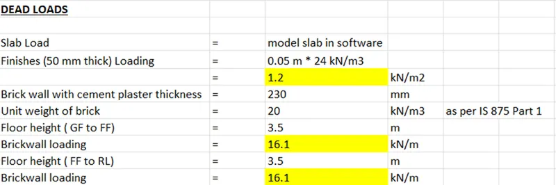
* The floor finishes loads are calculated by multiplying the floor thickness with the unit weight of RCC
* The brickwall loading is calculated by multiplying the wall thickness, height of the wall with the unit weight of the brick. The external and internal wall thickness is assumed as 230mm. The height between 2 floors is assumed as 3.5m
Result :-
Successfully complete to calculate dead load in design report based on IS code and apply dead load on the model
* Finishes of 50mm
* Slab thickness as per the design
* Brick wall load
* Roofing load
2)
Aim :-
Calculate live load in design report based on IS code and apply dead load on the model
Procedure :-
* Open MS Excel
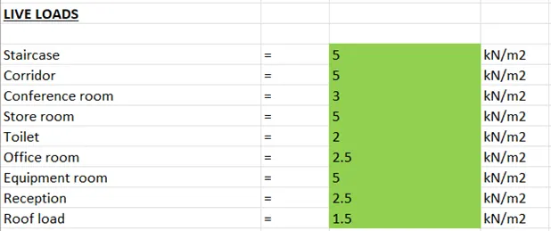
* The various rooms in our structure are listed one by one
* The corresponding live loads are obtained from the IS 875 Part 2 code book
Apply dead and live load
Dead load
* Go to Load – Load Cases
* Check the load cases
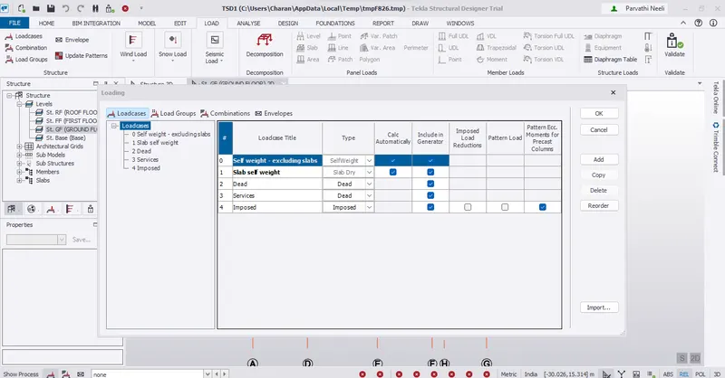
* Select the load as Dead load from the load case below
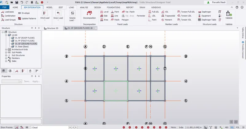
* First apply the floor finish load of 1.2 kN/m2
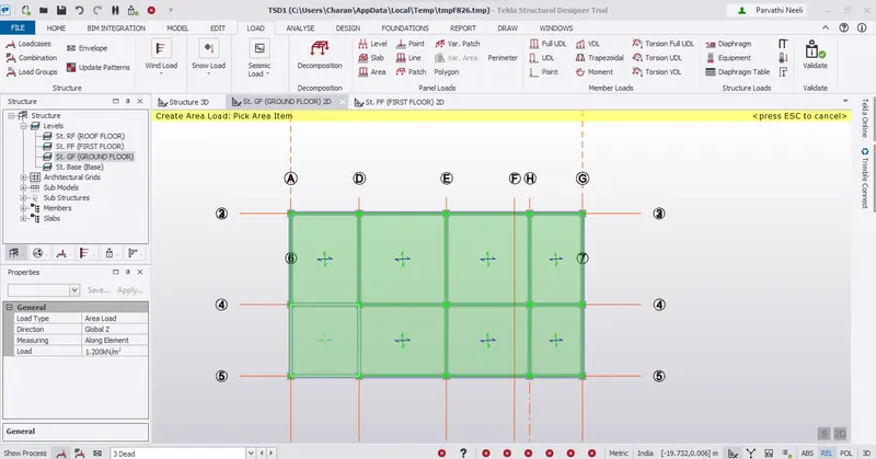
* Repeat the same for every other floor and validate the model
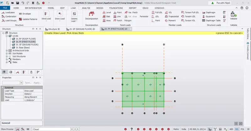
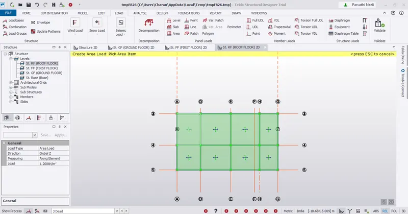
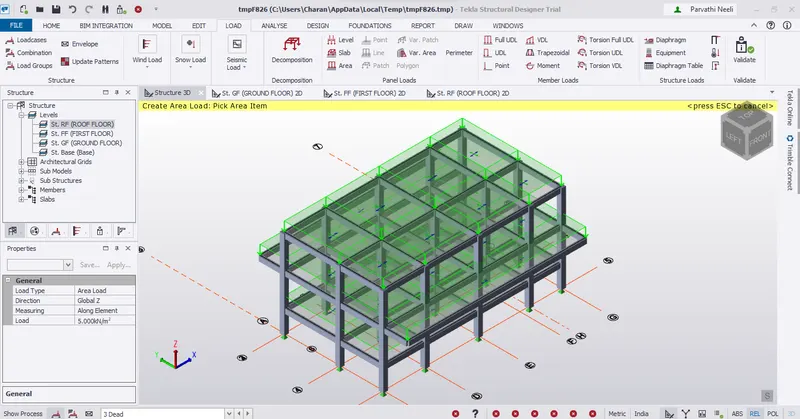
* Now lets apply the brickwall loading to GF and FF
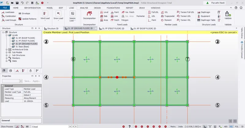
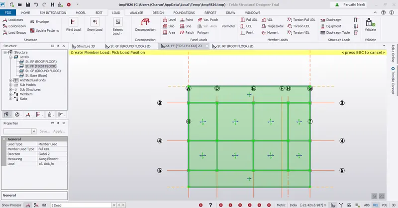
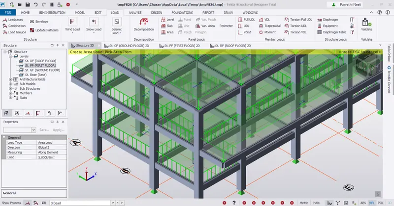
* Validate the model for any errors
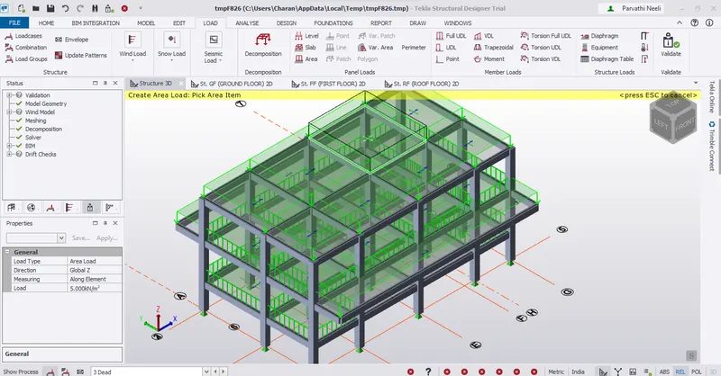
Live load :-
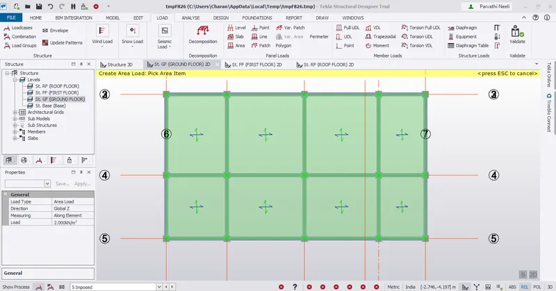
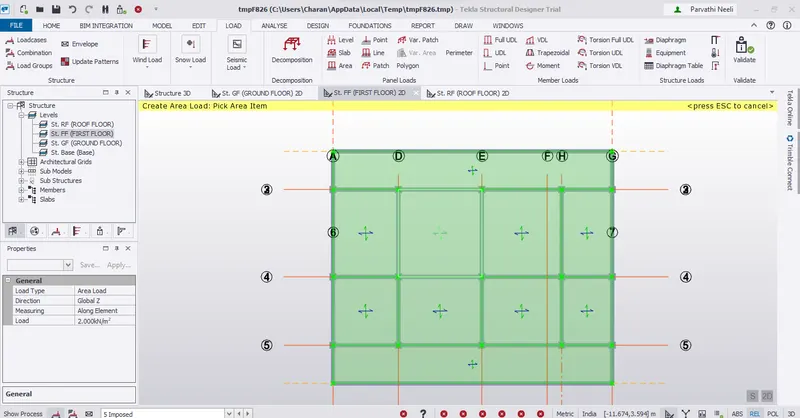
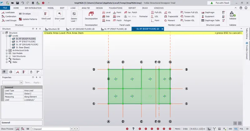
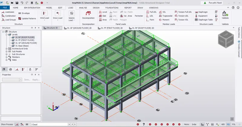
* Now lets apply the imposed load to the model by checking the layout
* Lets first go to GF and apply the loads
Result :-
Successfully complete to calculate live load in design report based on IS code and apply dead load on the model
3)
Aim :-
Generate manual wind loading in the design report based IS code as per the following input
* Basic wind speed = 50m/s
* Terrain category 2
Procedure :-
* Given, basic wind speed , Vb = 50 m/s ; Terrain Category = 2
* Length of the building, l = 19.225 m
* Breadth of the building, w = 10.7 m
* Height of the building, h = 9 m
Step 1: Finding Design Wind Speed:
* Referring to IS 875 P3, Vz = Vb k1 k2 k3 k4 according to Cl 6.3
Where Vz – Design wind speed
K1 – probability factor
K2 – terrain roughness and height factor
K3 – topography factor
K4 – importance factor for cyclonic region
* From table 1, k1 = 1
* From table 2, for height of the building 10 m and terrain category 2 , k2=1
* From Cl 6.3.3 , k3 = 1 since, theta < 3(flat terrain)
* From Cl 6.3.4, k4 = 1 for general structures
* Substituting all the above values, Vz = 50 * 1 * 1* 1 * 1 = 50 m/s
Step 2: Finding Design Wind Pressure:
* From Cl 7.2, wind pressure, pz = 0.6 Vz^2
* pz = 0.6 * 50 ^ 2 = 1500 N/m2
* pz = 1.5 kN/m2
Step 3: Design Wind Load:
Wind Load on Wall:
* From Cl 7.3.1, F = (Cpe – Cpi) A pz = Cp * pz
* Cpe is found from Table 5 of IS 875 P3 for h/w and l/w ratios
* h/w = 9 / 10.7 = 0.84
* l/w = 19.225/10.7 = 1.80

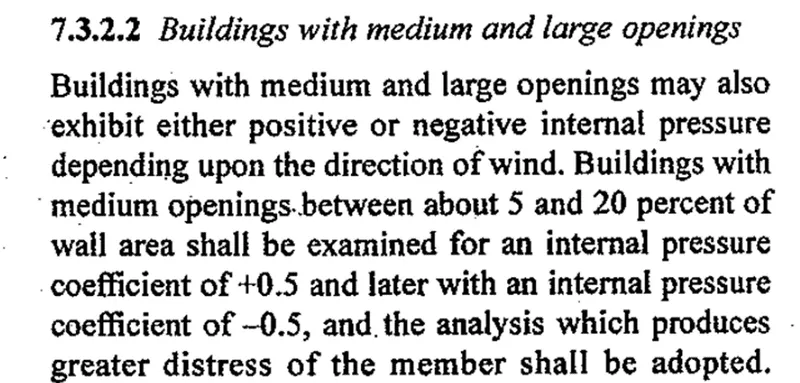
- Lets consider medium openings in which Cpi = + 0.5 / -0.5 according to Cl 7.3.2.2 of IS 875 part 3

Result :-
Successfully complete to Generate manual wind loading in the design report based IS code as per the following input
* Basic wind speed = 50m/s
* Terrain category 2
4)
Aim :-
Based on the above calculation apply the loadings on the model
Procedure :-
* For application of wind loads, its necessary to model wind panels
* Hence frames are created from Model – Frame
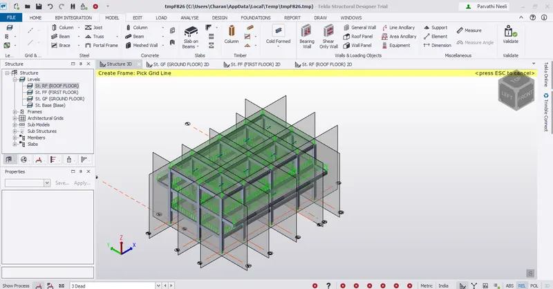
* Pick end frames and model wind and roof panels
* Model – Wall panel
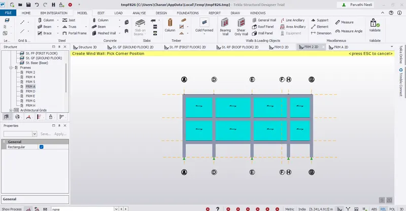
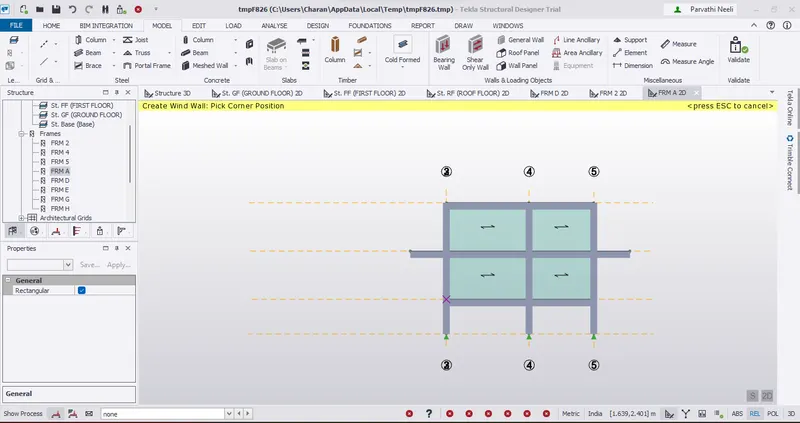
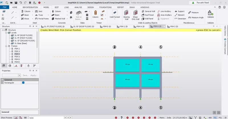
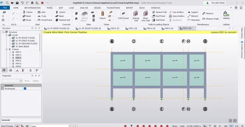
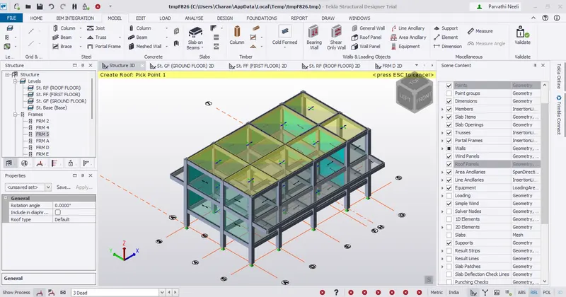
* Now lets start applying the wind loads in faces A,B,C and D
* Load – Load cases – Create 4 load cases for wind load
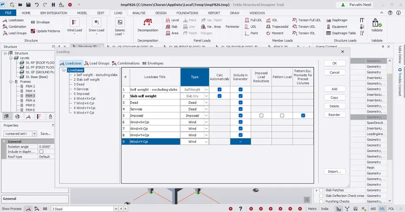
Now Apply the wind load
Wind+Y+Cpi :-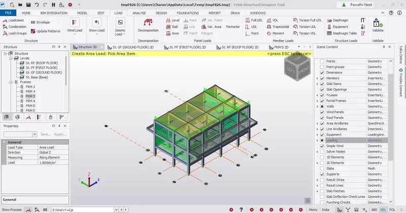
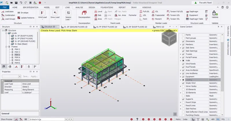
Wind+Y-Cpi :-
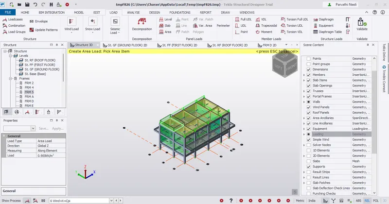
Wind+X+Cpi :-
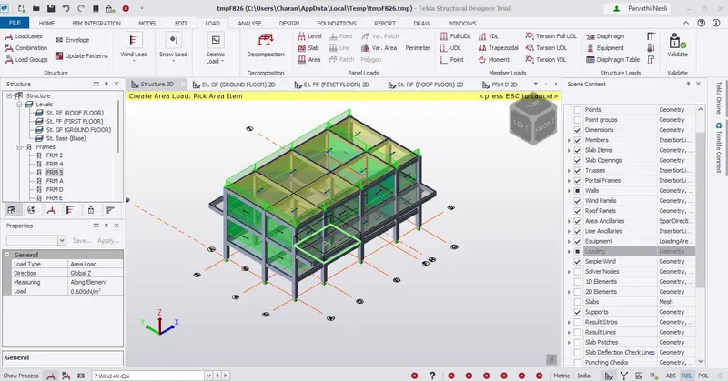
Wind+X-Cpi :-
Result :-
Successfully complete to based on the above calculation apply the loadings on the model