To Analysis and Design of Steel Structures using TSD
WEEK 6 CHALLENGE
1. Summarize your study for the bending moment, shear force and deflection diagrams foe the elements of the model.
Answer:
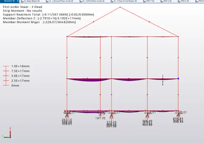
Bending Point:
It speaks about a member bending as a result of applied forces.
Simple supported beams subjected to specific udl and bending moment values are depicted in the image below.
Since every support is hinged, there is no reaction at the ends.
The central concave shape shows how the applied load bent the beam.
Shear Force:
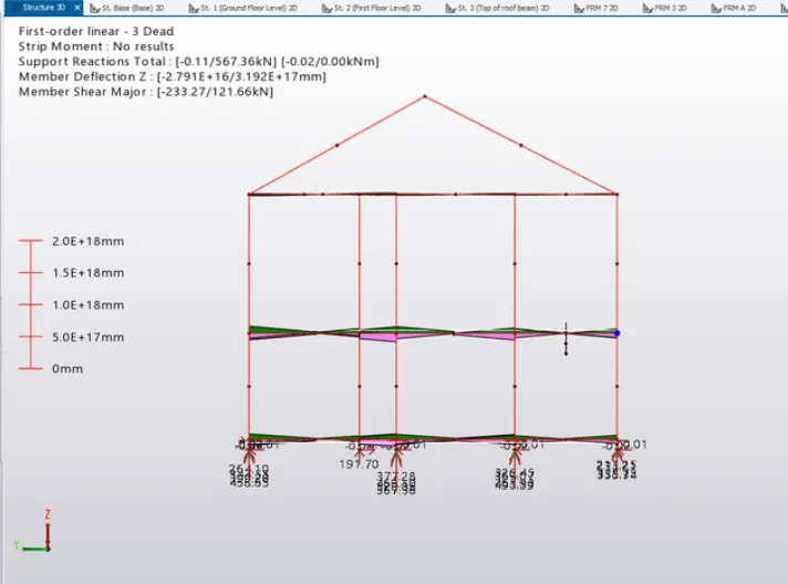
It is described as a system of two opposing, equal forces operating near together or side by side.
It happens at a beam's supports, where an upward force is exerted at both ends and a response is created at the bottom, resulting in the development of two equal and opposing forces in the system.
According to the description above, we can observe that the response in the following figure is zero in the center and maximal at the ends.
Diagrams of Deflection:
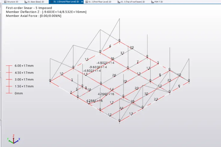
is used to describe how structural elements like beams and columns settle or distort.
The applied forces cause these components to shift somewhat out of place.
The maximum deflection allowed is span/250; if this value is exceeded, the member's dimensions need to be adjusted.
2. Based on the analysis design the member and outline the thought process in selecting the member sizes along with the foundation design.
Answer:
- The construction has been thoroughly examined.
- Identify the component or member that isn't working.
- Determine the cause of the member's failure.
- Select the member that can withstand bending if the failing member bends.
- The part that can withstand bending the most is the one with a higher section modulus.
- Check that the replaced member is not experiencing any shear failures or other problems at the same time.
- In a similar vein, replace the member with one that has a high shear capacity if it fails due to shear.
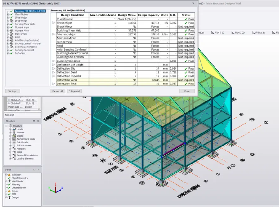
One way to describe this is low shear=0.6Vd. - Additionally, verify the member for deflection. If it does not meet the limiting deflection, replace it with the appropriate member in accordance with IS 800-2007 Table 6.
The beam member was found to be failing in a few areas during inspection, and the issue was fixed by enlarging the beam.
Design of the foundation:
Three requirements are met while choosing the design of the foundation member:
They are as follows:
One-way shearing
Two-way shearing
Using the internal force with the highest failure rate among the three listed above, the member's depth is estimated.
The footing member's size is determined by its bearing capability.
Regarding foundation design:
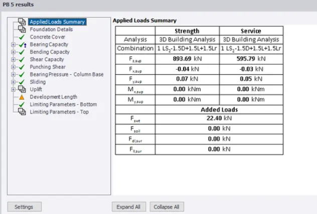
Navigate to the Ribbon's Foundation tab, choose Pad Base, and designate it for the column.
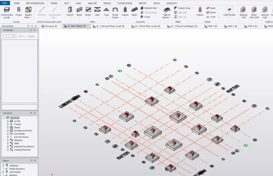
Result: Following the foundation pad's design, everything checked out.