Switch Bezel Design Week 8 Challenge
AIM:
Creation of Tooling Axis and Draft Analysis and creation of Door switch bezel and add thickness to it.
Given CLASS A SURFACE
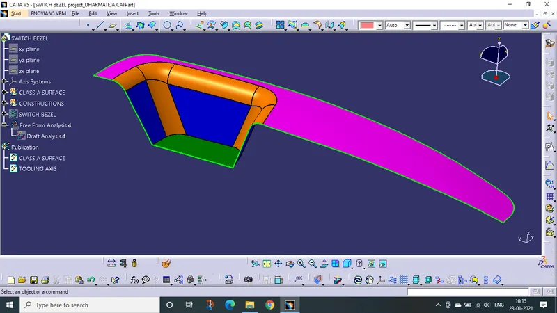
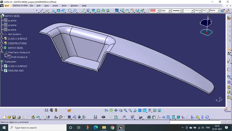
Picture of the 3D CAD WITH 2.5MM THICKNESS
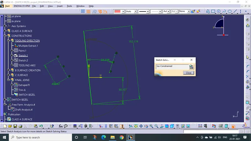
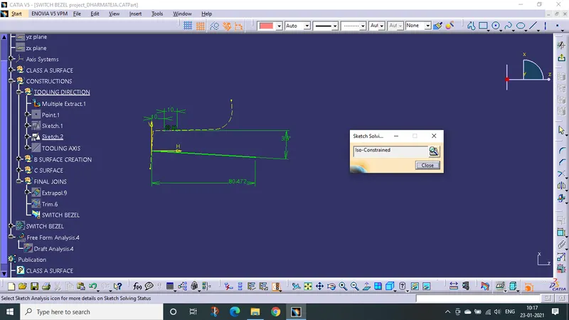
Picture of the sketches with Sketch solving status’s geometry tab
These sketches are used while creating tooling axis
Picture of the Detailed tree structure.
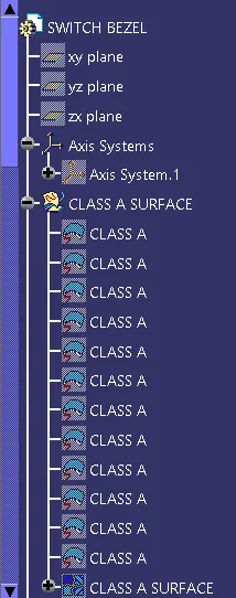
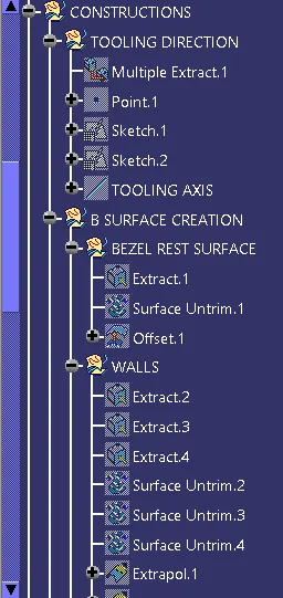
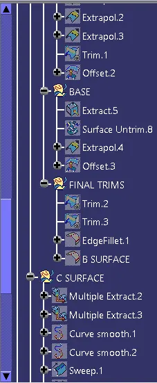
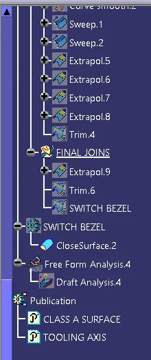
IMAGE OF FULLY CONSTRUCTED SURFACE MODEL OF SWITCH BEZEL
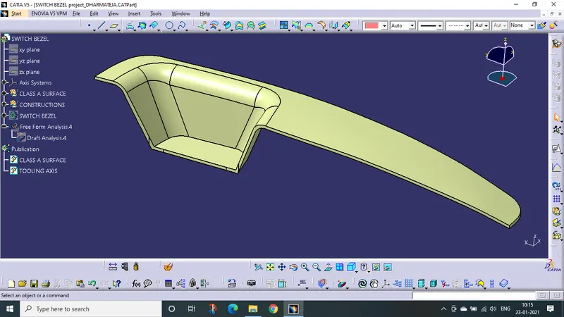
IMAGES OF TOOLING AXIS AND DRAFT ANALYSIS REPORT
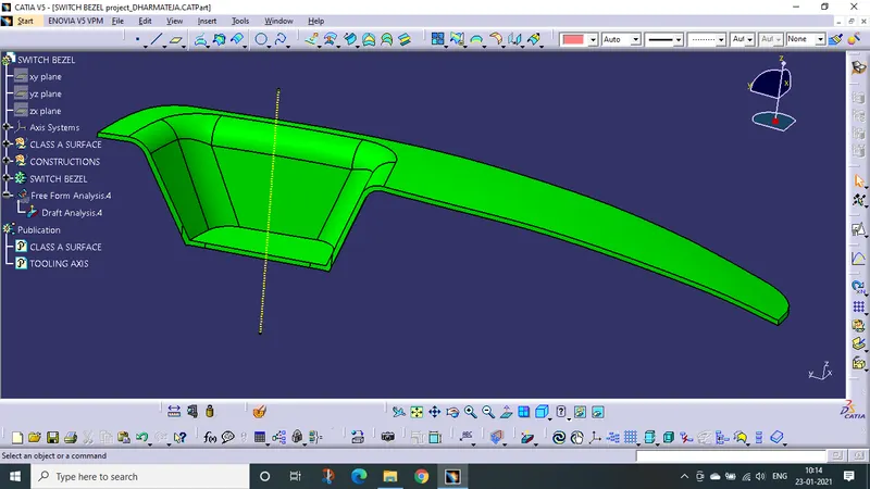
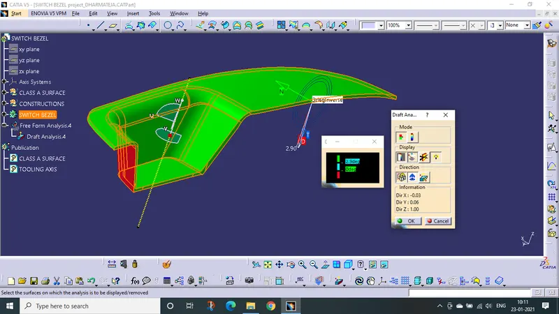
- Initially, we have to create a Tooling axis for the draft analysis.
- We have to extract the base surface of the switch bezel and we have to create a point on the surface.
- Then we have to create the intersection line with the YZ plane with class A surface as a reference, then we have created the point to point lines at the two sides of the switch bezel.
- The bisecting line is created by selecting line 1 and line 2with the point as reference and marked as axis-1.
- Then we have to create the intersection line with the XZ plane with class A surface as a reference, then we have drawn a line from the point and dimension the line length and the angle of the line from the intersection line and marked as axis-2.
- Tooling axis is created by bisecting of axis 1 and 2 with the point reference.
- Extracting all the surface of class A surface and they are untrimmed and extrapolate the edge along with the surface of extraction.
- Then we have offset all the extraction surface for 2.5mm in the outward direction and marked as the class B surface.
- Trim the extra surface of the class B surface and do fillet for the required edge with the proper dimensions.
- Extract the boundary from the class A surface and then smooth curve the boundary.
- Then sweep the smooth curve for 3 deg. This sweep surface is considered as class C surface.
- Join the class A and class C surface and they trimmed with class B surface to get the required surface model.
- And check whether the surface is fully close or not.
- And the surface is not fully closed, there are some greener areas. Because we have created the smooth curve. So in that time we have to extrapolate the class A surface and trim with the class C surface and then join class A and class C surface. Then trim with class B surface.
- The surface is fully closed and we have to change the surface to solid part.
- Now, we have to check the Draft analysis for solid surface of the door switch bezel.
- Before the draft analysis , we have to check whether the customize view parameters are in the material.
- In the solid surface , the Draft Analysis is in between 0 to 2.9 deg. Green above 2.9 deg, Sky blue 0 to 2.9 deg, Red below 0 deg.
- In the solid surface class A and class C surface are green in colour As they were above 2.9 deg ,and class B surface area is red in clour as it is below 0 deg.
- Hence the creation of 3D model with 2.5mm thickness, creation of Tooling axis and Draft analysis is finished.