Study of battery pack and it's temperature using simscape model.
Aim:
To study battery pack and it's temperature using simscape model.
Objectives:
01.
To summarize thermal management techniques for electric car battery pack.
02.
To Create a simple simscape model with a battery and show the temparature dependance in the performance.
03.
To study the resultants graph for different areas of contact of heat.
Introduction:
- Operation of electrochemical system.
- Efficiency and charge acceptance.
- Power and energy efficiency.
- Safety and reliability.
- Life and life-cycle costs.
Li-ion batteries are extremely sensitive to low and high temperatures. For battery packs it is important to regulate the pack to remain in the desired temperature range for optimum performance and life, and also to reduce uneven distribution of temperature throughout a pack which would lead to reduced performance. Importantly, the attainment of even temperature distributions through the battery pack eliminates potential hazards related to uncontrolled temperature build-up (Thermal runaway).
Cooling/Heating Methods:
- Thermal management systems using active cooling (forced circulation of air or liquid) have been proposed and simulated for lead-acid batteries in EVs applications.
- Air convection (natural or forced) quite often is insufficient for effective heat dissipiation from batteries under abuse conditions leading often to non-uniform temperature distributions within the battery pack.
- Indirect liquid cooling of battery packs (both passive and active) can prove an efficient method for dissipiation or addition of heat.
- However, it is desirable to keep the cooling fluid separate from the battery and so far small battery packs, cooling by fluid may not actually be possible.
- It is known that the desired operating temperature for most Li-ion batteries is 20ºC to 30°C, although ambient temperatures can vary from -50ºC to 50°C.
Thermal Management Systems:
- When designing battery pack should be compact, lightweight, have low cost manufacture and have easy access for maintenance.
- The management system should have low parasitic power, allow the pack to operate under a wide range of climatic conditions and provide ventilation if the battery generates potentially hazardous gases.
- The thermal management control strategy is enacted using an electronic control unit.
- The method employed is fundamentally to surround the cells with a conducting material, that is, a form of heat sink, and remove or add heat using fluid.
Problem statement:
01.
Prepare a report summarizing thermal management techniques for electric car battery pack.
02.
Create a simple simscape model with a battery and show the temparature dependance in the performance.
Also connect a resistor load of 10 Ohm.
03.
Compare the resultants graph for different area of contact of heat.
Solution:
01.
Prepare a report summarizing thermal management techniques for electric car battery pack.
Battery Thermal Management Techniques:
a. Air-Based BTMS:
The advantages of these systems are the low cost, simplicity, light extra weight and despite their low-conductivity and low-efficiency they are still studied by researchers and used in electric-driven vehicles. A first classification of air-based systems can be made considering whether it is natural or forced convection. Despite its simple structure, the natural method creates large thermal gradients in the battery pack and is highly dependent on ambient conditions. Therefore, a forced-air system is necessary for most applications, despite its higher costs and additional power consumption. A second classification of air-based systems is based on the source of the air, which can be external, cabin pre-conditioned or pre-conditioned by an auxiliary heat exchanger.
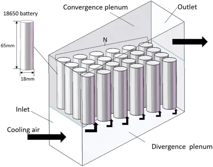
Fig01: Air-Based BTMS.
b. Liquid-Based BTMS:
Liquid-cooled systems are the most used in practical applications due to their high efficiency and compactness. Liquid possesses good heat capacity and heat transfer coefficient, representing a suitable solution for the BTM of EVs. Compared to an aircooling system, 2–3 times less energy is needed to maintain the same average temperature of the batteries. The disadvantages are the increased complexity, added weight, extra costs, rigidity of the structure. Moreover, a significant additional power is required to circulate the fluid at the desired flow rate, increasing the overall energy consumption of the vehicle.
Liquid-cooling is easily applicable for prismatic batteries due their regular shape, allowing a compact arrangement of the BTMS, while cylindrical batteries require special structures to integrate the cooling channels, increasing the system’s complexity and mass.
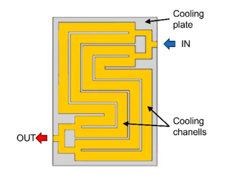
Fig02: Liquid-Based BTMS.
c. PCM-Based BTMS:
Phase change materials represent an interesting alternative to the conventional forced-air and liquid cooling systems, because it could allow the implementation of a passive BTMS. It is applied especially for cylindrical batteries, because it allows the filling of the unused spaces between the batteries. PCMs have high latent heat capacity and are able to maintain the temperature of the batteries in a small range, close to the melting temperature of the PCM. The melting point is in the 5.5–76 °C temperature range and the phase change process is usually not isotherm. In case of continuous charge and discharge cycles at high rates, there is the risk of the PCM melting completely, leading to thermal instability and leakage of the PCM. Moreover, the melting of the PCM automatically increases its volume, which must be considered when designing a PCM-based BTMS. Another disadvantage of PCMs is their low thermal conductivity, resulting in a difficult heat dissipation.
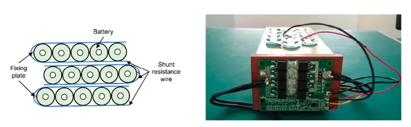
Fig03: PCM-Based BTMS.
d. Heat Pipe-Based BTMS:
Heat pipes are heat transfer devices with extremely high thermal conductivity, 90 times higher than copper ensuring better heat dissipation and temperature uniformity. They represent a passive, compact, lightweight BTMS, with no need of maintenance and long life cycle. The working principle consists in the phase change of the internal working fluid, which absorbs heat at the evaporation section and releases it at the condensation section. As long as there is a temperature gradient between the two sections, the transfer of heat goes on, without any power consumption. Despite its very high thermal conductivity however, in most applications heat pipe is coupled with forced air or liquid cooling for a more effective heat dissipation at the condensation section. Heat pipe-based BTMSs are studied mostly for prismatic and pouch batteries due to the adaptability of the shapes and the large available contact areas, while in case of cylindrical batteries special attention needs to addressed to the contact surface between heat pipe and batteries.
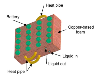
Fig04: Heat Pipe-Based BTMS.
e. Hybrid BTMS:
Hybrid BTMSs usually combine active and passive methods, with the aim of enhancing the heat transfer process of passive systems and offering the possibility to actively
control their working process. In general, PCMs are used for a better temperature uniformity and the active system reduces the risk of heat saturation, while HPs are used for their high thermal conductivity which significantly improves local heat transfer and the active system enhances the heat release at the condensation section. Although forced air can be successfully implemented as the active system for lower thermal load systems, liquid cooling offers higher efficiency. Another classification criterion is the combination method, which can be parallel, series or both. The main disadvantages of hybrid BTMSs regularly are their weight, volume, complexity and energy consumption.
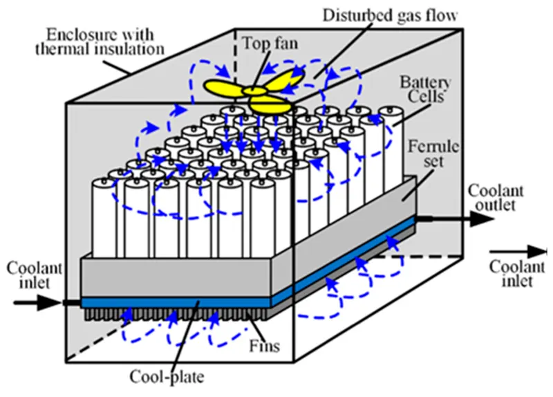
Fig05: Hybrid BTMS.
02.
Create a simple simscape model with a battery and show the temparature dependance in the performance.
Also connect a resistor load of 10 Ohm.
Case-I: Temperature dependancy model without resistor.
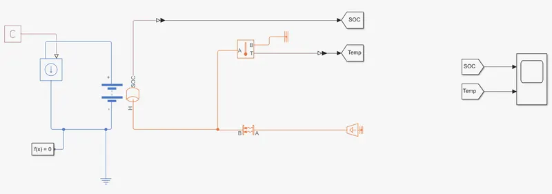
Fig06: Interface of Temperature dependency model without resistor.
Model consists of following blocks:
- Constant block: To define the rate of discharge of the battery in Amperes (4 A).
- Controlled Current Source block: To moniter and control the flow of current from the battery.
- Table-based battery block: Instrumented + Show Thermal port.
- Temperature Source block: To define the temperature (293.15 K) input to the system under study.
- Convective Heat Transfer block: To define the Area (1e-4 m^2) and the Heat transfer coefficient (20 w/[m^2*K]) of the system under study.
- Temperature Sensor block: To sense and measure the temperature of the system.
- Goto Tag block: To define the value of a parameter of a system under study and assign it to the 'From Tag'.
- From Tag block: To define the value of a parameter of a system under study received from the 'Goto Tag'.
- Scope block: To display the results of the system under study.
- Configuration Solver block: To support the simulation of the system under study.
- PS-Simulink Converter block: To convert the Physical system into simulink signal.
- Electrical Reference block: Electrical reference for the electrical blocks of the system under study.
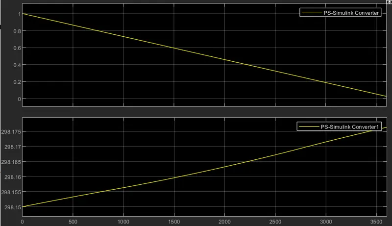
Fig07: Results for Temperature dependency model without resistor.
The SOC of the system reaches to 2% within a hour and Temperature rises to 298.17 K from 298.15 K.
Case-II: Temperature dependancy model with resistor.
Link: Temperature dependency of the battery pack.
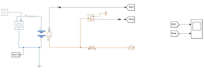
Fig08: Interface of Temperature dependency model with resistor (10 Ohm).
Model consists of following blocks:
- Constant block: To define the rate of discharge of the battery in Amperes (4 A).
- Resistor block: To define the value of resistance (10 Ohm).
- Controlled Current Source block: To moniter and control the flow of current from the battery.
- Table-based battery block: Instrumented + Show Thermal port.
- Temperature Source block: To define the temperature (293.15 K) input to the system under study.
- Convective Heat Transfer block: To define the Area (1e-4 m^2) and the Heat transfer coefficient (20 w/[m^2*K]) of the system under study.
- Temperature Sensor block: To sense and measure the temperature of the system.
- Goto Tag block: To define the value of a parameter of a system under study and assign it to the 'From Tag'.
- From Tag block: To define the value of a parameter of a system under study received from the 'Goto Tag'.
- Scope block: To display the results of the system under study.
- Configuration Solver block: To support the simulation of the system under study.
- PS-Simulink Converter block: To convert the Physical system into simulink signal.
- Electrical Reference block: Electrical reference for the electrical blocks of the system under study.
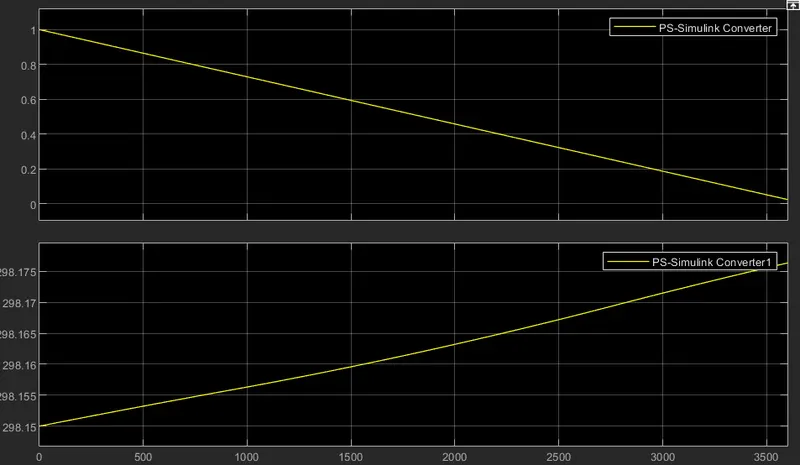
Fig09: Results for Temperature dependency model with resistor (10 Ohm).
The SOC of the system reaches to 2% within a hour and Temperature rises to 298.17 K from 298.15 K.
There is nearly no change in the SOC and temperature of the battery in both Cases I and II. That is because resistance of 10 Ohm is very very low value to affect the performance of the battery. Otherwise the battery of less capacity and voltage rating is better option.
03.
Compare the resultants graph for different area of contact of heat.
Case-I: Temperature dependancy model with Area of Contact of Heat = 1 m^2.
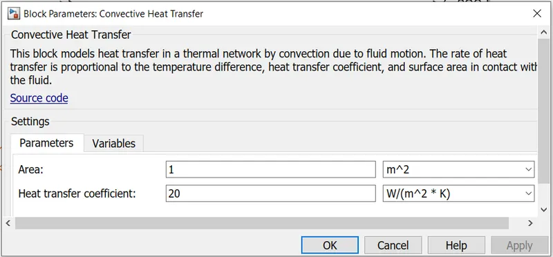
Fig10: Area of contact for convective heat transfer = 1 m^2.
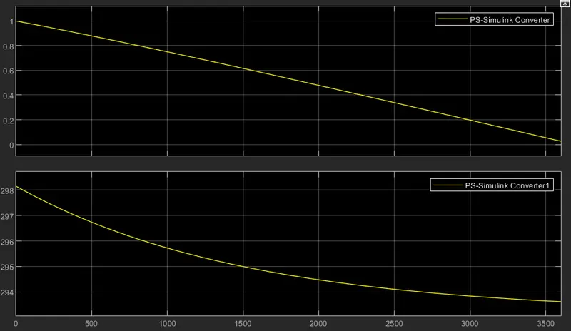
Fig11: Results for area of contact for convective heat transfer = 1 m^2.
The SOC of the battery reaches to 2% within a hour and the temperature of the battery falls to 293.7 K from 298.2 K.
Case-II: Temperature dependancy model with Area of Contact of Heat = 10 m^2.
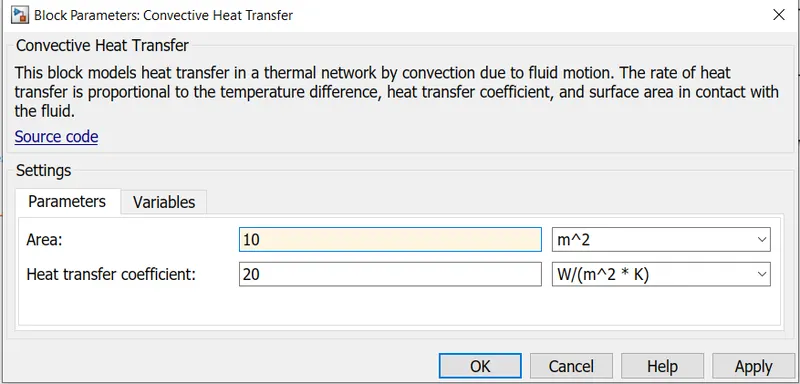
Fig12: Area of contact for convective heat transfer = 10 m^2.
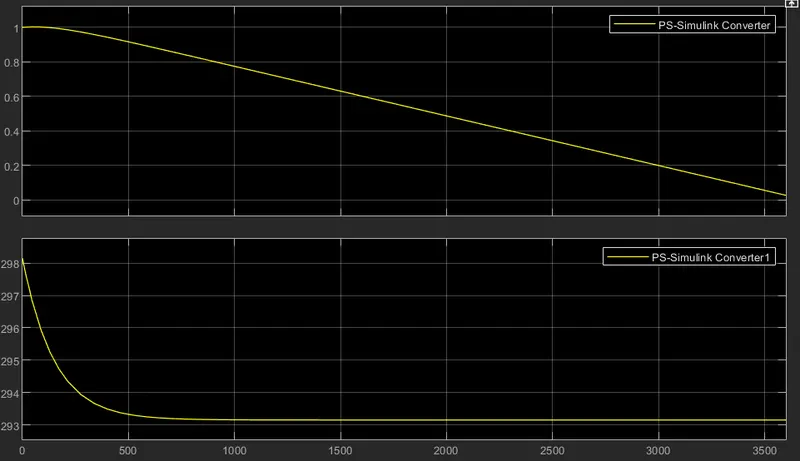
Fig13: Results for area of contact for convective heat transfer = 10 m^2.
The SOC of the battery reaches to 2% within a hour and the temperature of the battery falls to 293.2 K from 298.2 K.
Comparitively lower is the risk of thermal runaway when compared to Case-I.
Comparing both Cases I and II we can conclude that the rate of heat transfer is directly praportional to the area of contact of the system for convective heat transfer.
Greater the area greater is the heat transferred and thus lowerer the temperature achieved by the system.
Conclusion:
In this study we learnt the various techniques for Thermal management of the of the battery packs in EVs.
We also learnt the effects of resistors on the performance of the battery pack.
We also learnt the effects of area of contact of the system for convective heat transfer on the performance of the battery pack.