Structural Modelling using Etabs 2018
Aim
- To conceptualize a framing plan layout and then model the given G+7 building situated in zone 5 in Etabs
- To develop the structural model that comply with provisions of IS 1893 and IS 13920.
- To run the modal response spectrum analysis and to check analysis results of the etabs model for inter-storey drift requirements, vertical & planar irregularities, minimum shear wall requirements, maximum axial load ratio for column and shear walls, effective moment of inertia for beams and columns etc.
Introduction:
- ETABS is an engineering software product that caters to multi-storey building design and analysis.
- Modelling tools and templates, code base load prescriptions, analysis methods and solution techniques, all coordinated with the grid like geometry unique to this class of structure.
- Basic or advanced systems under static or dynamic conditions may be evaluated using ETABS.
- Fundamentals to ETABS modelling is the generalisation that multi-storey buildings typically consist of identical or similar floor plans that repeat in the vertical direction.
- Once modelling is complete ETABS automatically generates and assigns code-based loading conditions for gravity, seismic, wind and thermal forces. Users may specify an unlimited number of load cases and combinations.
- Outputs and display formats are also practical and intuitive. Moment, shear and axial force diagrams, presented in 2D and 3Dviews with corresponding data sets, may be organised into customisable reports.
- Here, in this challenge we are going to model an entire G+7 building with the floor plan using ETABS software.
Procedure:
Step 1)
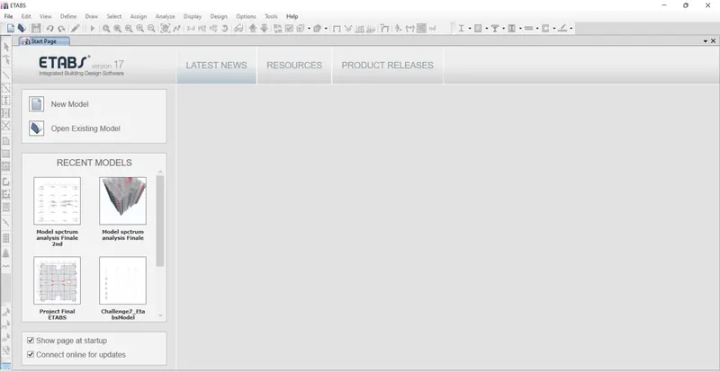
- We have to open the ETABS software and click on the new model option from the file menu.
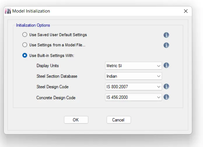
- Now in the model initiation window desired units, Design codes which are to be used was selected.
Step 2)
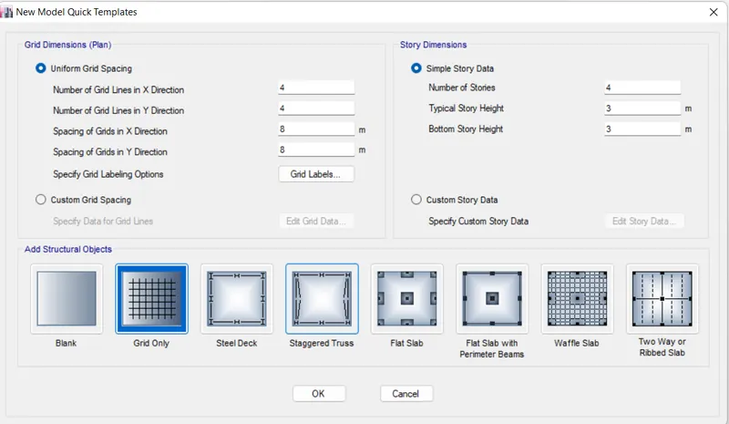
- In New Model Quick templates under grid dimensions select the custom grid spacing and then click edit grid data.
- The grid dimensions were inserted according to CAD file drawing as follows.
Step 3)
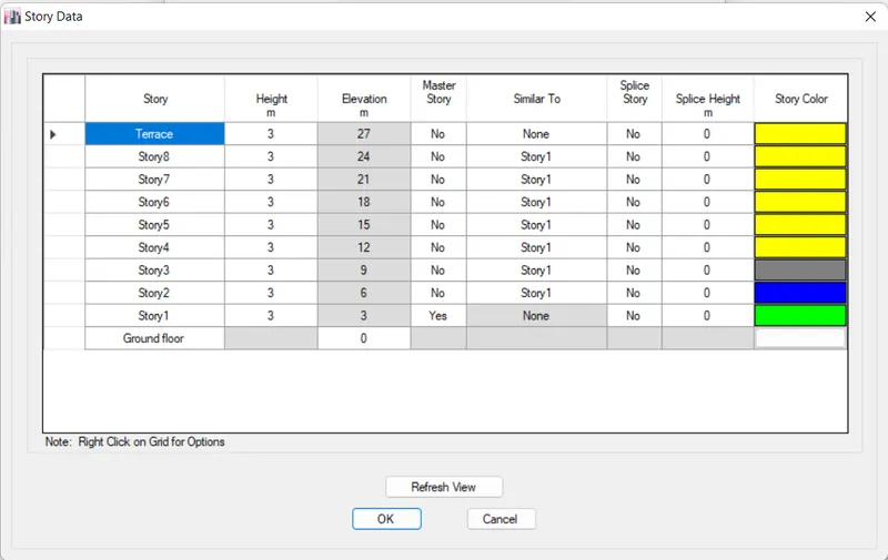
- Now we have to enter the Story data as per cad files. (It's G+7 building)
- Floor to floor height is given as 3m
- For that click on New Model Quick templates under Story dimensions select the custom story data and
- then click edit story data.
- Now input the storey details as given in question and story 1 was selected the master story as and was applied to rest story from 2nd story to roof and then click OK.
Step 4)
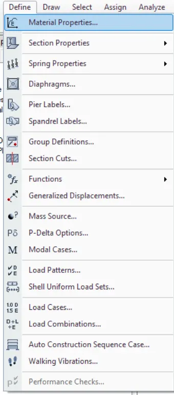
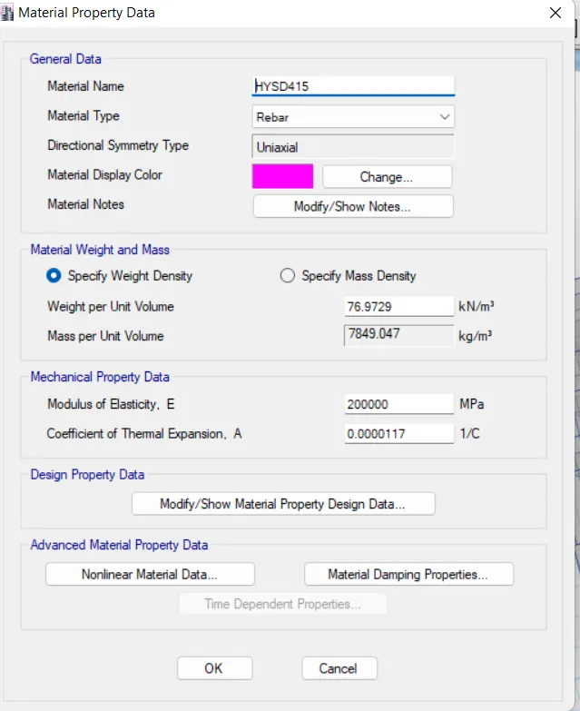
- Now we have to define material properties
- For that Define the properties of elements - Define menu
- Select material properties.
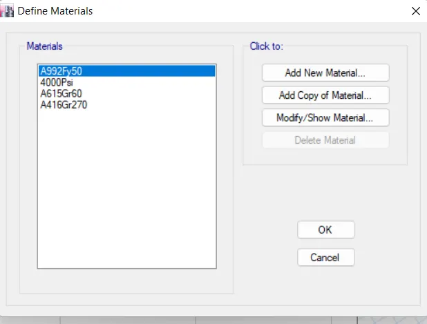
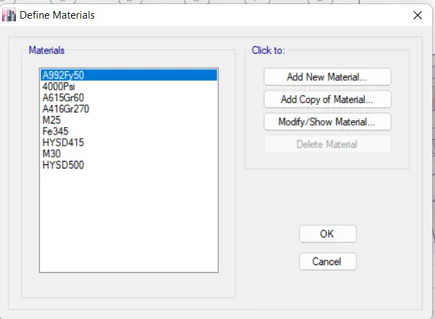
- Once you select material properties a following dialog box will appear
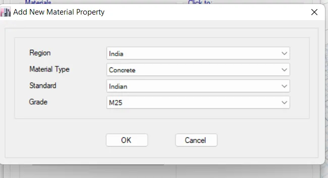
- Define the materialsAdd New material
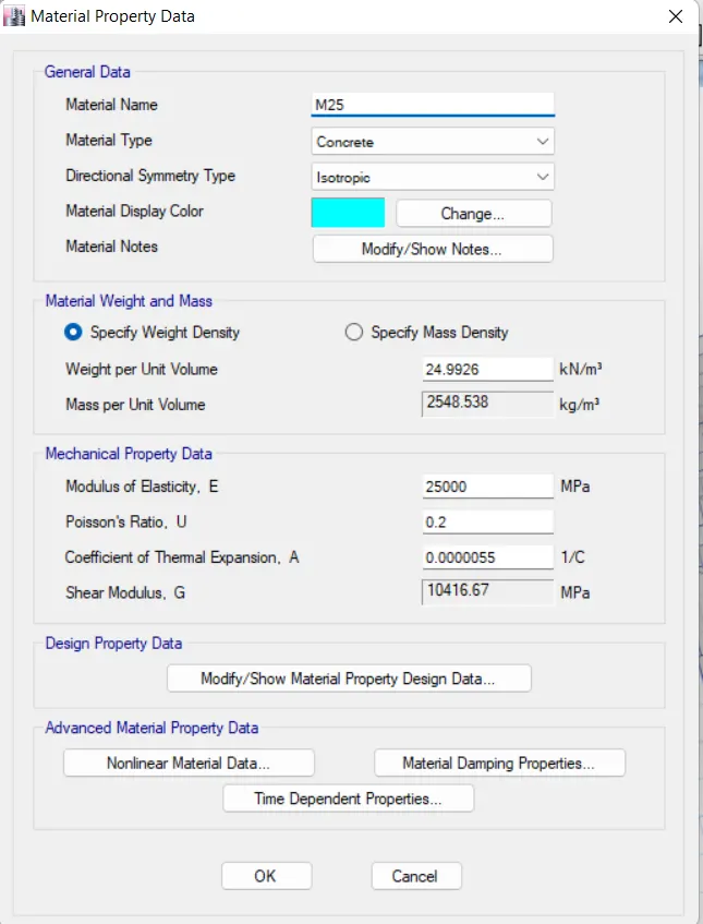
- Select M25 grade of concrete
Step 5)
- Now we have to add section properties -
- For that Click on Define Properties-Section Properties-frame sections options.
- From the frame properties dialogue box click on add new property option.
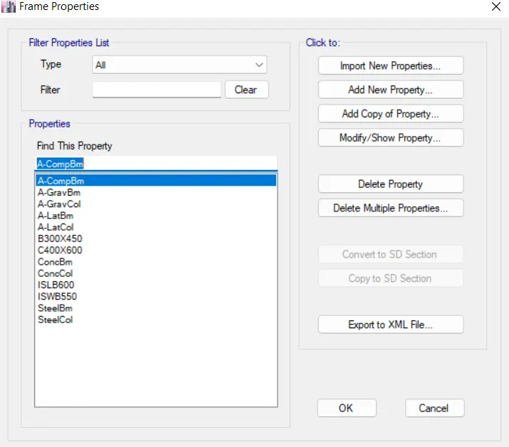
- Click on Add new Property
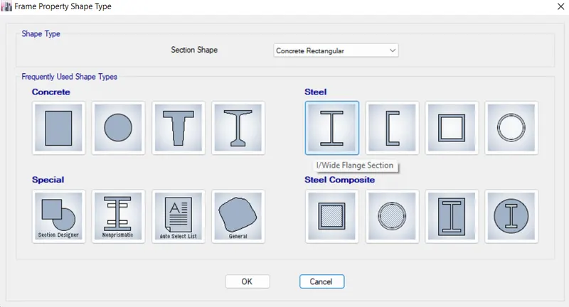
- Select frame property shape type select the rectangular concrete option and click OK.
- Beam details (250x450) was provided as shown in figure and then click on Modify/ Show reinforcement under reinforcement section.
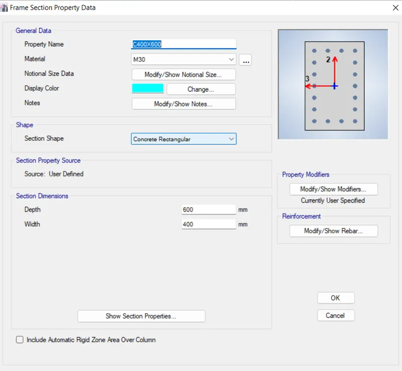
- Click on Modify/Show Rebar
- Select M3 Design Only (Beam) and chose the rebar materials as shown and click Ok
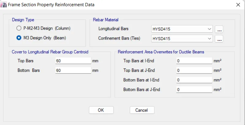
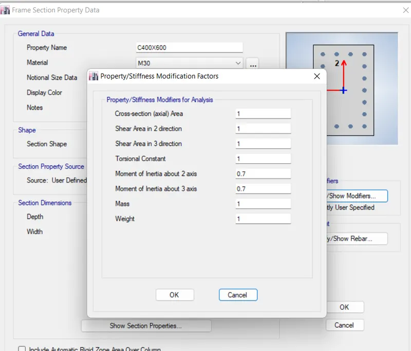
- Click on Modify/Modifier
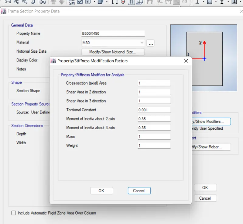
- The torsional constant was reduced to 0.001, The Moment of Inertia about 2 and 3rd axis was reduced to 0.35 respectively
- Similarly the beam of size 300x500 is also added by following same steps
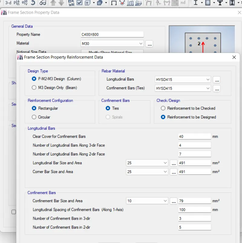
- From property list we can see the columns of size 400x400 and 400x600 and Beams of size 250x450 and 300x500.are added
Step 6)
- To design the slab initially for select slab section from the section properties under define menu
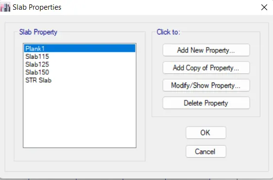
- select add new property option
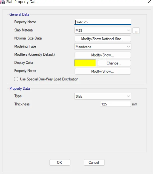
- Slab properties like thickness and other details are added as shown below and then click ok
- Give the thickness = 125 mm
Step 7)
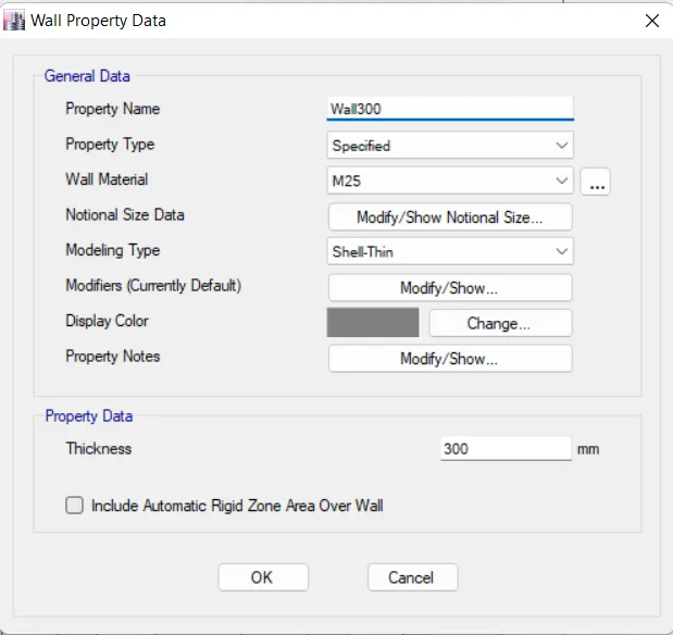
- Now we have to add the shear walls
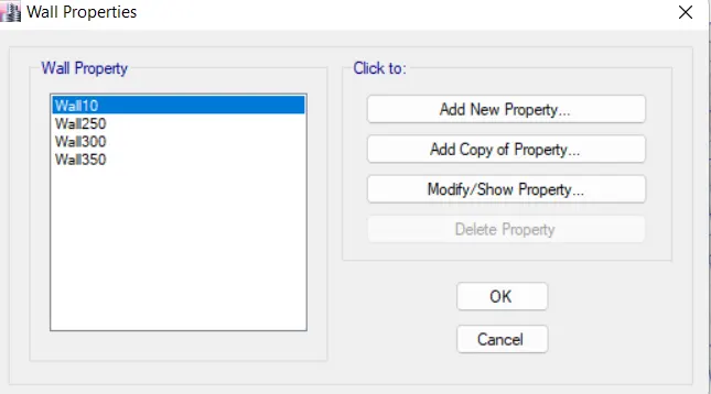
- For that click on Define- section properties-Wall sections
- Assign the wall thickness as 300 mm
Step 8)
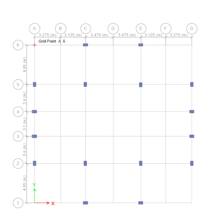
- First we have to draw the columns by using quick draw column option
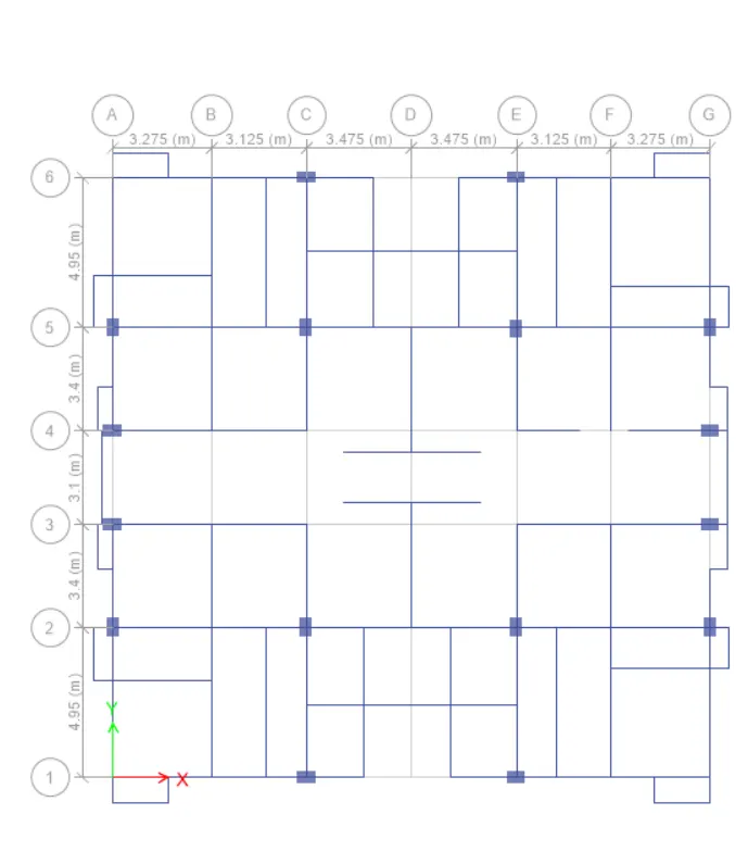
- Next we need to add the beams using quick draw beams option as shown below
- Next we need to add the secondary beams by using quick draw secondary beams option as shown below
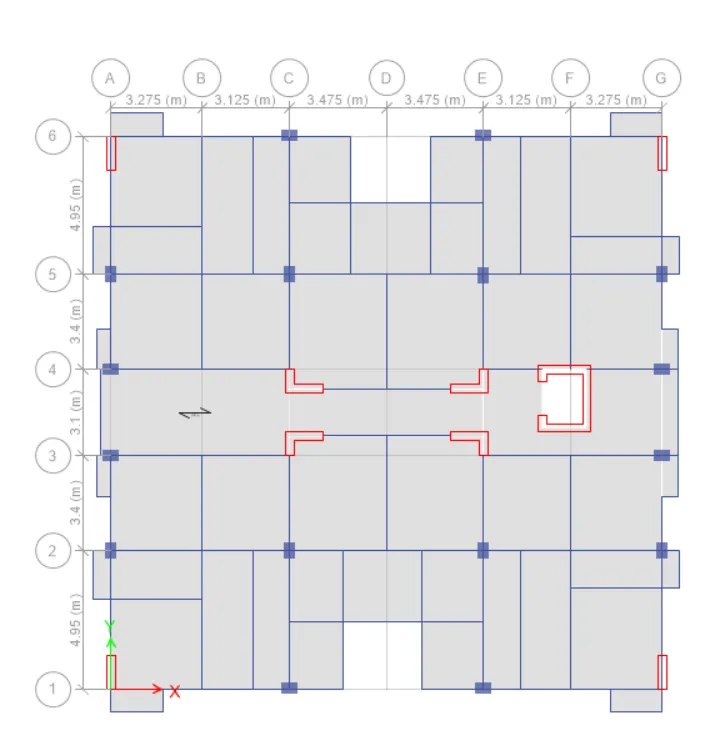
- Next we have to add the slab by using quick draw floor plan/walls
- Next we have to add the shear walls in required locations as shown below
- And add the balcony wherever required
Step 9)
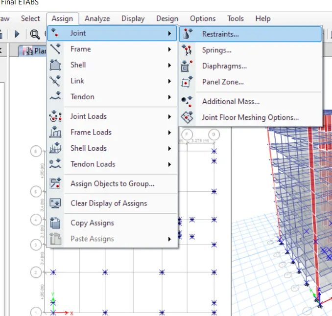
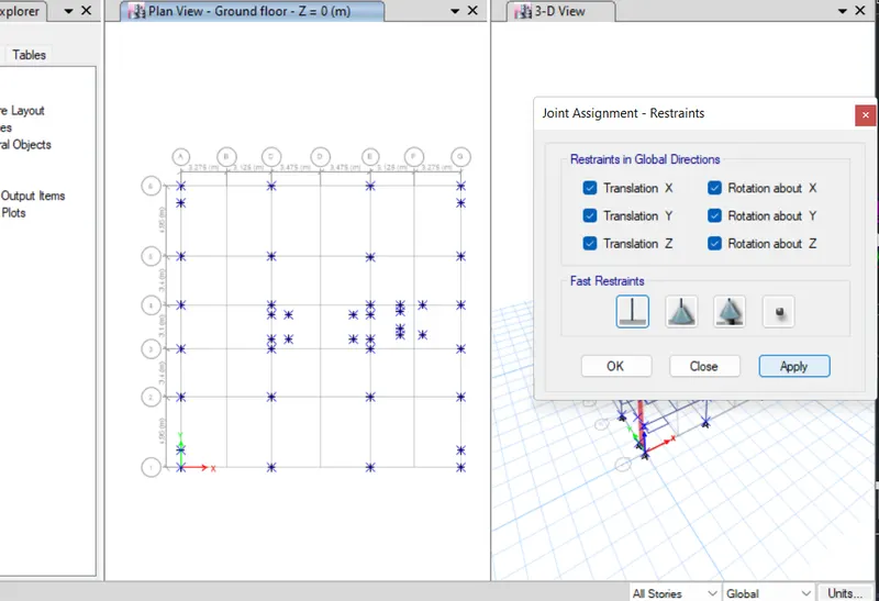
- Now we go to the base plan and select all base joints
- Next we select the restraints from the joint option as shown below
- Select the connection as fixed
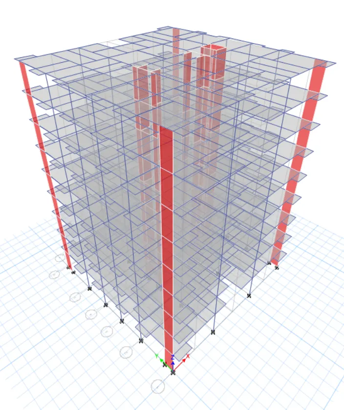
- 3D view after assigning all properties
Step 10)
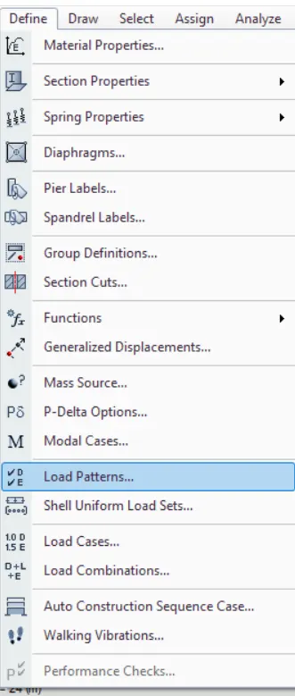
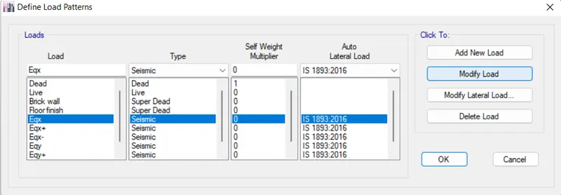
- Now we have to assign loads patterns
- Select Define - by load patterns to open the Define load pattern dialogue box.
- The various loads which are applied are as shown below
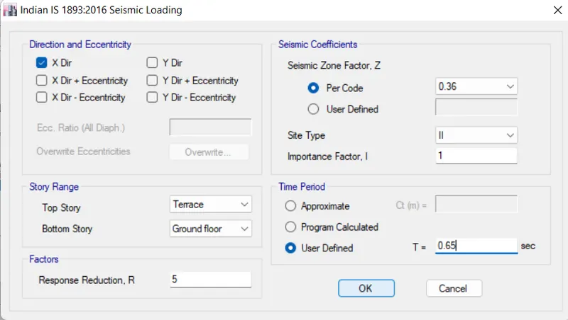
- The direction and eccentricity were selected as the X direction
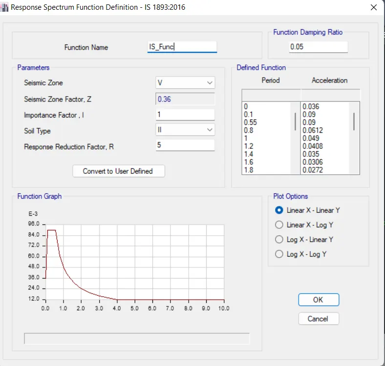
- The Response Reduction Factor R was taken as 5
- Seismic zone is 5 so Z=0.36
- Soil type was taken as III
- Importance factor for residential building with less than 200 is taken 1 and time period is taken as 0.5
Step 11)
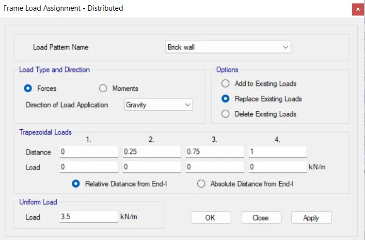
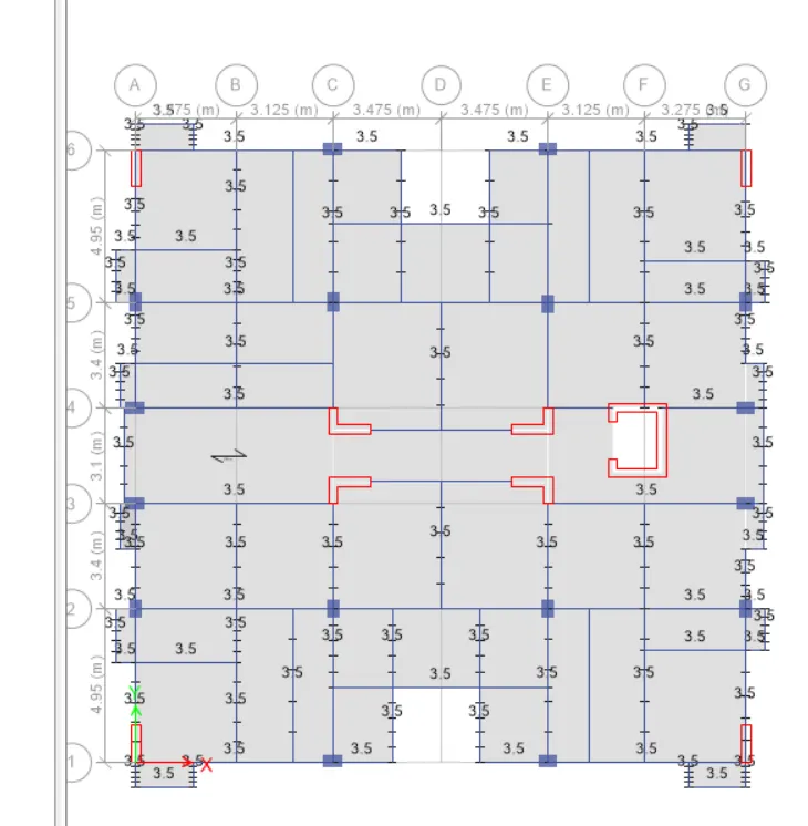
- Now we have to assign the loads to the strucure
- Brick wall load -3.5 kn/m2
Live loads were applied to slabs next.
- As per IS 875 in residential buildings its 2kn/m^2 for rooms and bathrooms whereas its 3Kn/m^2 for staircase, lift and balcony
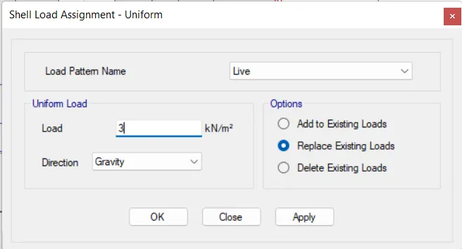
- Live loads are applied repectively.
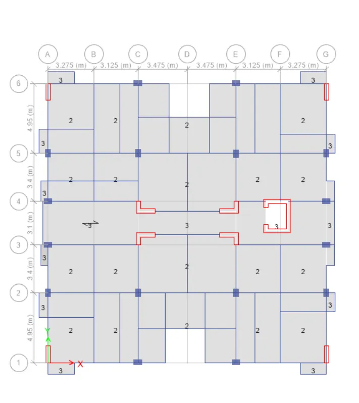
Floor Finish
- In the same way select slabs to assign floor finish which is 1.25kn/m^2 for rooms and bathrooms whereas its 3Kn/m^2 for staircase balcony.
Step 12)
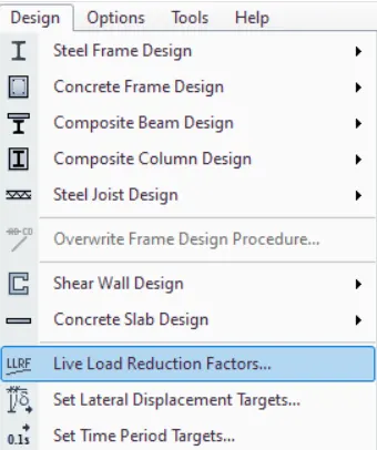
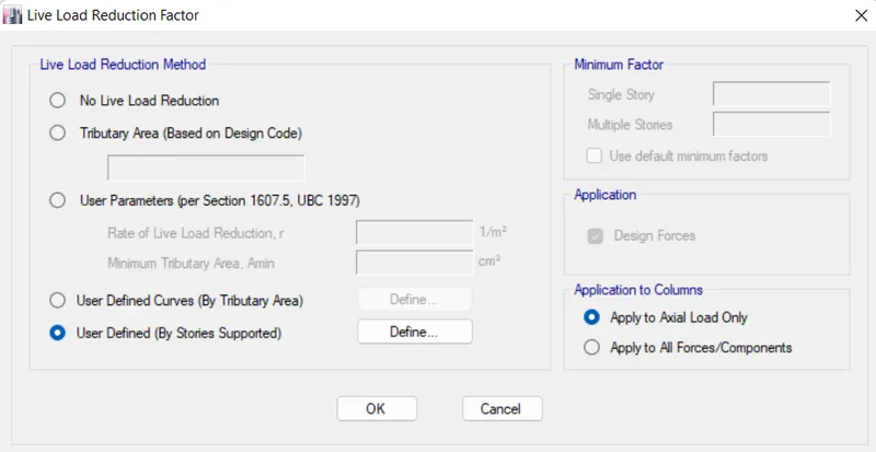
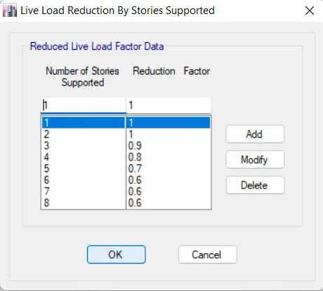
- Live load reduction factor as per IS 875 code ii) For Building Above 10 Storey we have to reduced live load by 50%
Step 13)
- Now we have to assign Mass source
- For that Define menu - mass source options to open the mass source dialogue box.
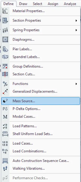
- Now select Modify mass source data option and click OK
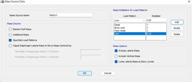
- Now mass source data was provided as shown and load pattern was also added to it.
- For live load upto 3Kn/m2- we have to assumed some fraction of live load i.e 25%
Step 14)
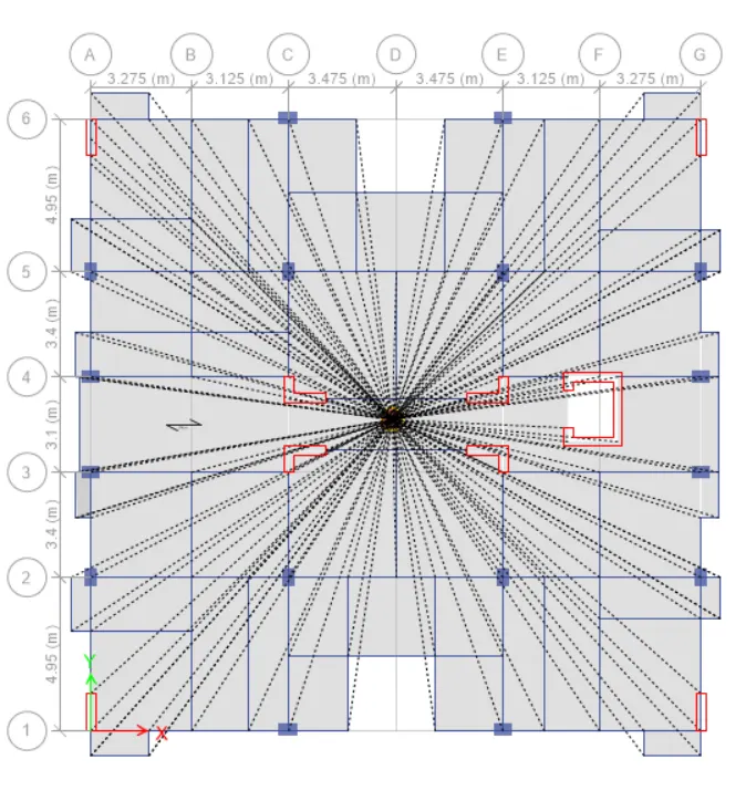
- Now we haev to assign diaphragm
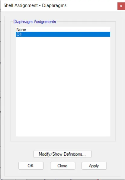
- In assign menu select Shell followed by Diaphragm to open the shell Assignment diaphragm dialogue box
- Select D1 from the diaphragm assignments and click apply followed by OK.
- The Diaphragm D1 is applied and is as shown below.
Step 15)
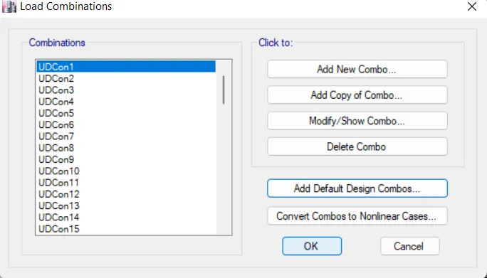
- Now we have to add the load combinations
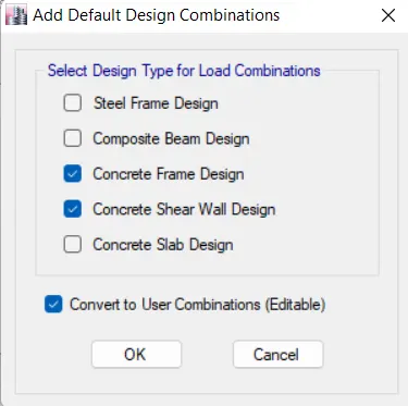
- Click on add default design combo
Step 16)
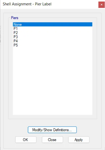
- Next we have to select the pier label from the shell option as shown below
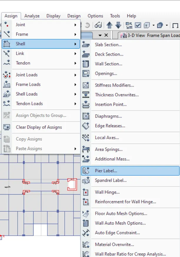
- Before going to the shear wall design we have to assign the names for the as P1, P2 etc.
Step 17)
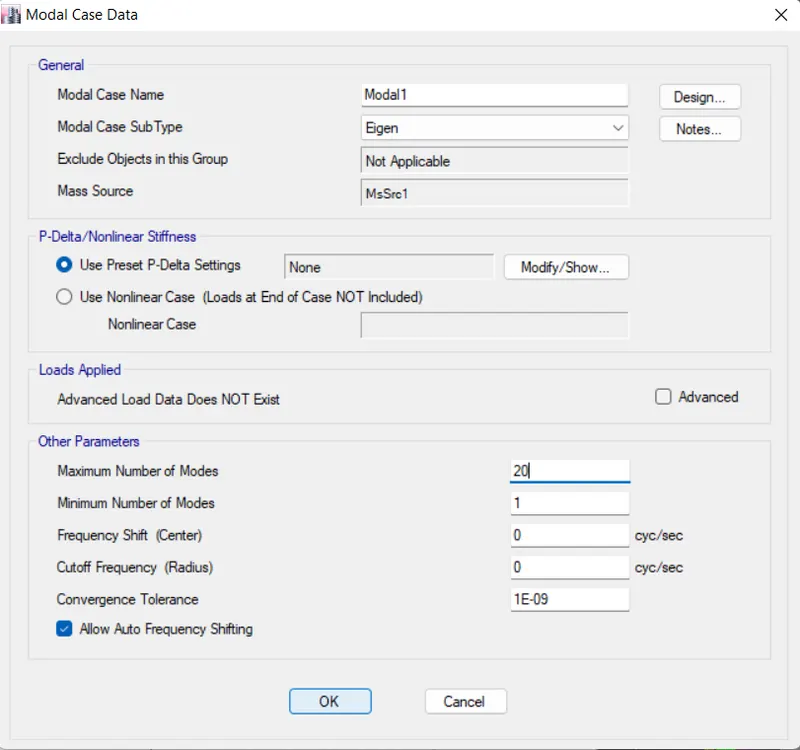
- Now we have to create a Modal analysis
- For that define tab-modal cases- and select modify
- Enter the data's as shown in image. Maximum number as 20.
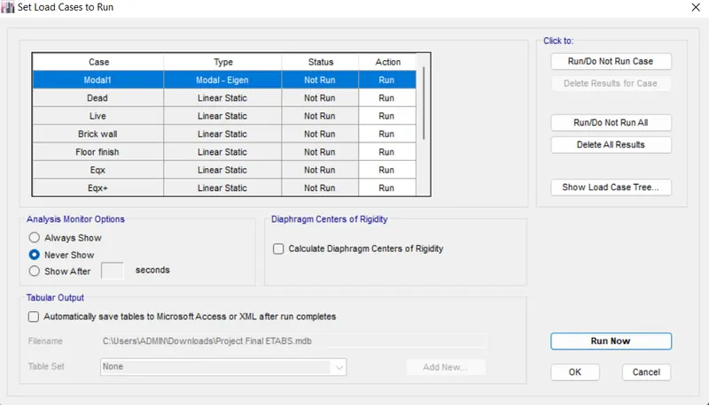
- Here both spectrum analysis and equivalent lateral force are done at the same time
Step 18)
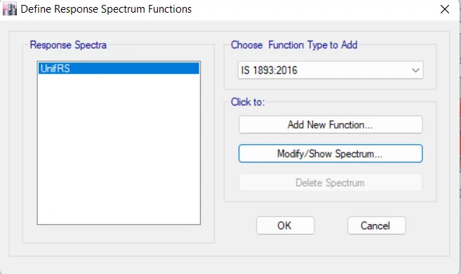
- New function was defined as per the IS 1893 for response spectrum analysis.
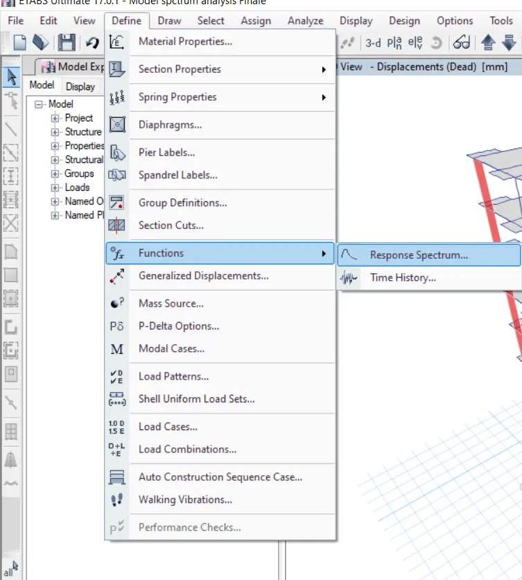
- After selecting the response spectrum the new tab is visible,
- In that we choose IS 1893:2016 from the "Choose function type" and click on the Modify/Show option as shown below
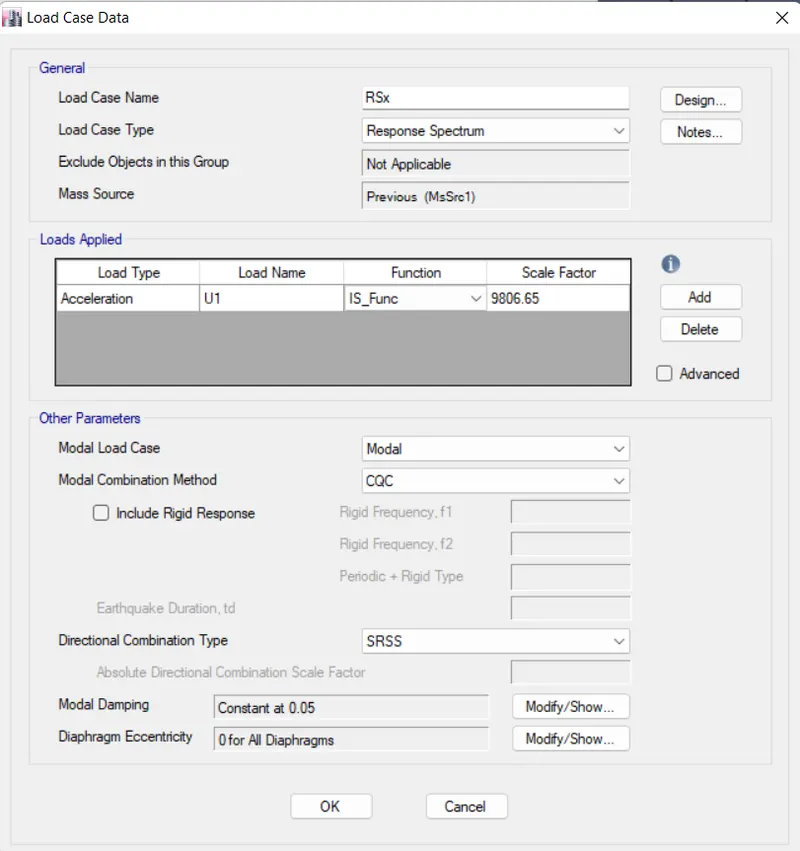
- Two load cases was defined for response spectrum analysis and set default scale
Step 19)
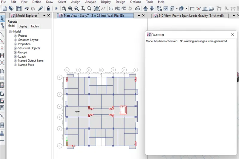
- Now we have to check the model for errors, go to Analysis tab and select check model.
Step 20)
- Now Run the model
- Click on Run Analysis
Step 21)
- In order to obtain the new scale factor, go to display-show table-structural output base shear.
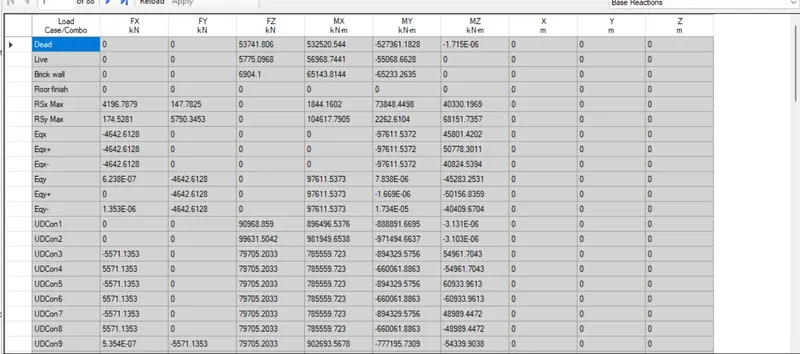
- As per IS 1893 design base shear should not be less than design base shear,
- If so then scale factor needs to be multiplied with calculated base shear by estimated base shear.
Step 21)
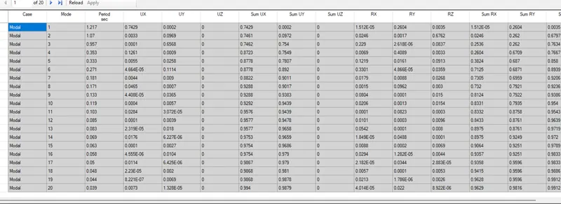
- Modal Participation ratio -
- Modal number check for that go to Display-Show Tables-Analysis Results-Structure Output-Modal Information-Modal mass participation ratio.
- According to Is 1873 clause 7.1, the natural period corresponding to fundamental torsional mode of oscillation
- should not be greater than sum of two fundamental translational mode of oscillation (Tx+Ty>Txy)-from table 1.25+1.115=2.365>0.832. hence no torsional irregularity.
- IS 1873-clause 7.1, table 6 the first three modes contribution should be more than 65% of mass participation factor in each principal plan direction. Here it is 0.738>0.65.
- Here Tx=1.254 and Ty=1.115, differ by 12%, hence conclude that building is regular in mode of oscillation in two principal plan direction
- From modal number, maximum required is 13 number as it captures more than 90% of mass in all 6 degrees of freedom.
Step 22)
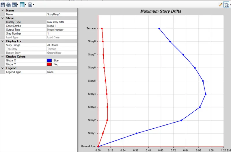
Storey response plot:
- For this go to Display-Story Response Plot-Maximum Storey drift
- Here storey response for maximum storey drift is less than 0.004 for both X and Y
Base Shear Checking:
- click on Load Display >Load Type as Eqx > Show Fx load.
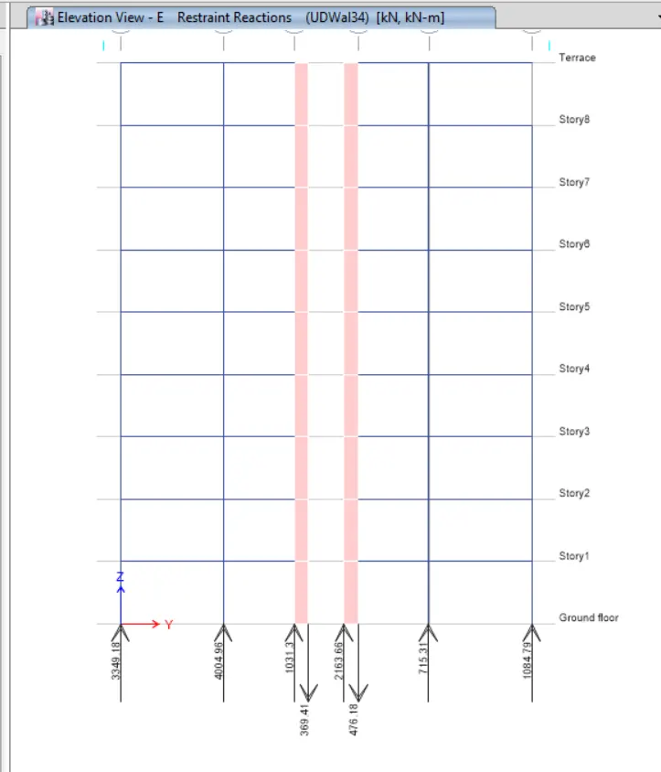
- From code- shear wall shoud should take at least 80% of the load.
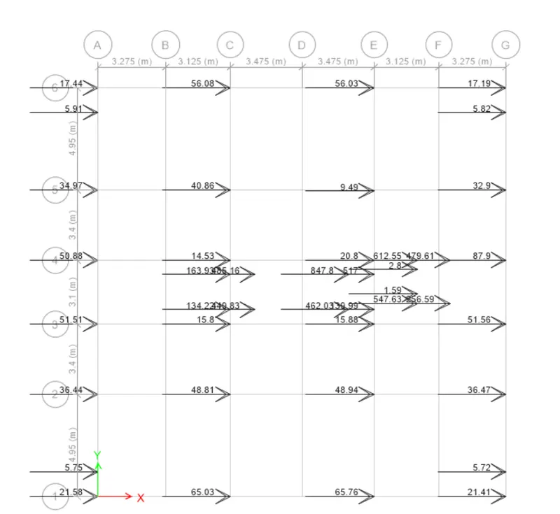
- in order to find the percentage, 3174/3800-83.5% >80%, provided shear wall is sufficient in x-direction.
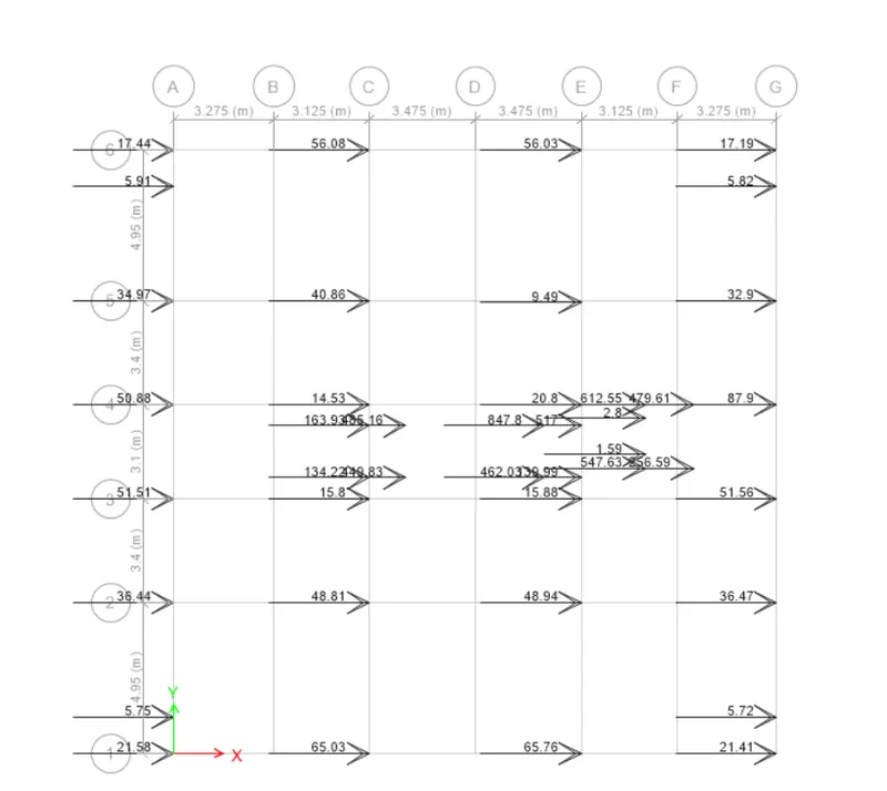
- 3181/3800=83% which is greater than 80% so the shear wall provided in Y direction is sufficient.
Check for column under tention:
- Under loading conditions 4b and 4d are found to be under tension
Check for aspect ratio for both column and shear wall
- Column
- The aspect ratio should be less than 0.4 (aspect ratio = force/cross section area*fck)
- Considering first load combination (1.5DL), force 1580KN.
- Aspect ratio=1580-1000/400*600*30-0.22< 0.4, hence ok.
- Shear wall:
- The aspect ratio should be less than 0.28.
- Force is 7.22kN.
- Aspect ratio=7.22*1000/1200*300*25 0.08-0.28, hence ok.
RESULT
- The structural model of the G+7 model is designed for given architectural planning using Etabs.
- Frame model which satisfies both code provision are analysed.
- Columns, shear walls and beam are provided in possible symmetrical way without much offsets.
- Analyses is done for modal number, base shear storey drift aspect ratio, irregularity etc.,
- As per the analyses result, building is bit flexible in y-axis, as shear wall are sufficient add additional column as provided in y-direction to meet the maximum storey drift limit.