Creating a Floor plan, Footing detail and Isometric view using AutoCad
AIM
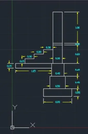
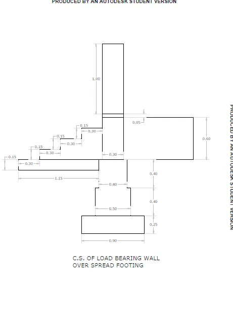
To draw C.S of load bearing wall over spread footing using AutoCAD Software
PROCEDURE
- Open AutoCAD
- In the command prompt type QNEW
- Click on imperical template, advaced setup, decimal
- In the command prompt type units.
- Type= decimal, precision = 0.00, angle = decimal degree
- In the command prompt type ds
- Snap spacing (x and y spacing=0.5)
- grid spacing (x and y spacing=0.5)
- In the command prompt type REC (RECTANGLE)
- specify first corner point 1,11
- In command prompt click dimensions
- specify length of the rectangle 0.90
- specify width of the rectangle 0.25
- In the command prompt type REC (RECTANGLE)
- specify first corner point 1.2, 1.25
- In command prompt click dimensions
- specify length of the rectangle 0.50
- specify width of the rectangle 0.40
- In the command prompt type REC (RECTANGLE)
- specify first comer point 1.25, 1.65
- In command prompt click dimensions specify length of the rectangle 0.40
- specify width of the rectangle 0.40
- In the command prompt type REC (RECTANGLE)
- specify first comer point 1.30, 2.05
- In command prompt click dimensions
- specify length of the rectangle 0.30
- specify width of the rectangle 0.60
- In the command prompt type REC (RECTANGLE)
- specify first comer point 1.30, 2.65
- In command prompt click dimensions
- specify length of the rectangle 0.30
- specify width of the rectangle 0.05
- In the command prompt type REC (RECTANGLE)
- specify first corner point 1.30, 2.7
- In command prompt click dimensions specify length of the rectangle 0.30
- specify width of the rectangle 1.0
- In the command prompt type REC (RECTANGLE)
- specify first comer point 1.25,2.05
- In command prompt click dimensions
- Specify length of the rectangle 1.15
- specify width of the rectangle 0.15
- In the command prompt type line
- specify starting point 0.40,2.05
- In the command prompt type @0.15<90
- In the command prompt type @ 0.3<0
- In the command prompt type @0.15<90
- In the command prompt type @ 0.3<0
- In the command prompt type @0.15<90
- In the command prompt type @ 0.3<0E
RESULT
C.S of load bearing wall over spread footing
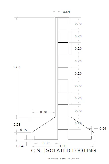
AIM:
To draw C.S Isolated footing using AutoCAD Software
PROCEDURE:
- Open AutoCAD
- In the command prompt type QNEW
- click on imperical template, advaced setup, decimal
- In the command prompt type unit
- Type= decimal, precision = 0.00, angle = decimal degree
- In the command prompt type ds
- Snap spacing (x and y spacing= 0.5)
- grid spacing (x and y spacing=0.5)
- In the command prompt type line
- In the command promt specify start point 1,1
- In the command prompt type @1<0
- In the command prompt type @0.15<90
- In the command prompt type line
- In the command prompt type 1.04,1.04
- In the command prompt type @0.38<0
- In the command prompt type @1.96<90
- In the command prompt type @0.17<0
- In the command prompt type @1.96<270
- In the command prompt type @0.38<0
- In the command prompt type @0.05<90
- In the command prompt type line
- In the command prompt type 1.04,1.04
- In the command prompt type @0.05<90
- In the command prompt type line
- In the command prompt specify start point 1.42,3.00
- In the command prompt type @0.04<180
- In the command prompt type @1.60<270
- join coordinate points (1.38,1.40) and (1, 1.15) using line command .
- In the command promtp specify start point 1.59,3.00
- In the command prompt type @0.04<0
- In the command prompt type @1.60<270
- join coordinate points (1.63,1.40) and (2,1.15) using line command
- click on the line in which coordinate points are (1.42,3.00) and (1.59,3.00)
- In the command promt type offset
- In the command prompt type distance 0.20
- In the command prompt click multiple (click on the objects till you get the number of
RESULT:
C.S Isolated footing
AIM:
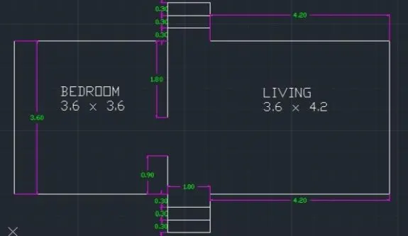
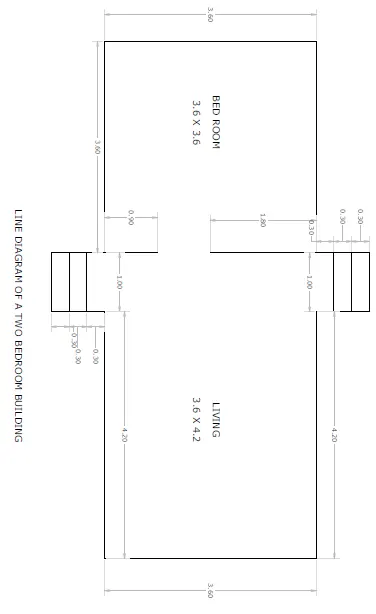
To draw a line diagram of a two bedroom building
PROCEDURE:
- Open AutoCAD
- In the command prompt type QNEW
- click on imperical template, advaced setup, decimal In the command prompt type units
- Type= decimal, precision = 0.00, angle = decimal degree
- In the command prompt type ds
- snap spacing (x and y spacing= 0.5)
- Grid spacing (x and y spacing= 0.5)
- In the command prompt type line
- In the command prompt specify start point 1,1
- In the command prompt type @3.60<0
- In the command prompt type @0.90<270
- In the command prompt type @1<0
- In the command prompt type @0.90<90
- In the command prompt type @4.20<0
- In the command prompt type @3.60<90 . In the command prompt type @4.20<180
- In the command prompt type @0.90<90
- In the command prompt type @1<180
- In the command prompt type @0.90<270
- In the command prompt type @3.60<180
- In the command prompt click close
- In the command prompt type line
- In the command prompt specify start point 4.60,1
- In the command prompt type @0.90<90
- In the command prompt type line
- In the command prompt specify start point 4.60 4.60
- In the command prompt type @1.80<270
- In the command prompt type offset
- In the command prompt type 0.30
- click on the line in which coordinate points are (4.60, 0.10) and (5.60,0.10)
- click on the previous line to get segments
- click on the line in which coordinate points are (4.60, 5.50) and (5.60,5.50 )
- click on the previous line to get segements
RESULTS:
line diagram of a two bedroom building
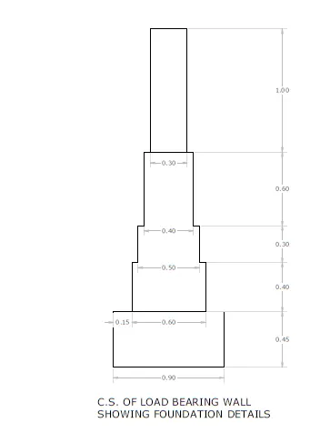
AIM:
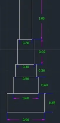
To draw c.s of load bearing wall showing foundation details
PROCEDURE:
- Open AutoCAD
- In the command prompt type QNEW
- click on imperical template, advaced setup, decimal
- In the command prompt type units Type decimal, precision = 0.00, angle = decimal degree
- In the command prompt type ds
- snap spacing (x and y spacing=0.5)
- grid spacing (x and y spacing= 0.5)
- In the command prompt type REC (RECTANGLE)
- specify first comer point 1,1
- In command prompt click dimensions
- specify length of the rectangle 0.90
- specify width of the rectangle 0.45
- In the command prompt type REC (RECTANGLE)
- specify first comer point 1.15,1.45
- In command prompt click dimensions
- specify length of the rectangle 0.60
- specify width of the rectangle 0.40
- In the command prompt type REC (RECTANGLE)
- specify first corner point 1.20,1.85
- In command prompt click dimensions
- specify length of the rectangle 0.50
- specify width of the rectangle 0.30
- In the command prompt type REC (RECTANGLE)
- specify first comer point 1.25, 2.15
- In command prompt click dimensions
- specify length of the rectangle 0.40
- specify width of the rectangle 0.60
- In the command prompt type REC (RECTANGLE)
- specify first comer point 1.30, 2.75
- In command prompt click dimensions
- specify length of the rectangle 0.30
- specify width of the rectangle 1.00
RESULT:
c.s of load bearing wall showing foundation details
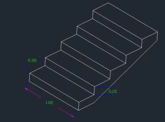
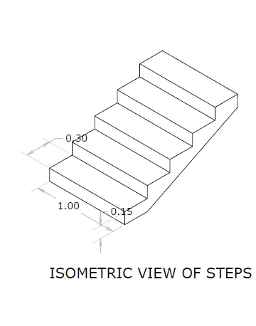
AIM:
To draw Isometric view of steps using Autocad
PROCEDURE:
- Open AutoCAD
- In the command prompt type QNEW
- click on imperical template, advaced setup, decimal
- In the command prompt type units
- Type- decimal, precision = 0.00, angle = decimal degree
- In the command prompt type ds
- In drafting settings (ds) off "snap on and off "grid on"
- select on isometric snap
- keep ortho (18) on
- In the command prompt type line
- Specify the point or select a point
- In the command prompt type 1 (distance)
- press 15 (isodraft) to get the line in desired directon
- In the command prompt type 0.15 (distance)
- press f5 (isodraft) to get the line in desired directon
- In the command prompt type 0.30 (distance)
- press f5 (isodraft) to get the line in desired directon
- This process done till the steps are formed
RESULT:
Isometric view of steps.
AIM:
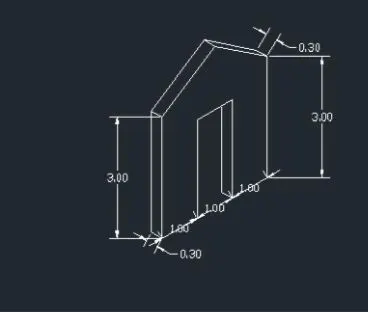
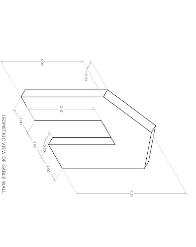
To draw isometric view of gable wall PROCEDURE:
- Open AutoCAD
- In the command prompt type QNEW
- click on imperical template, advaced setup, decimal
- In the command prompt type units
- Type= decimal, precision = 0.00, angle = decimal degree
- In the command prompt type ds
- In drafting settings (ds) off "snap on and off "grid on
- select on isometric snap
- keep ortho (18) on
- In the command prompt type line
- Specify the point or select a point
- press f5 (isodraft) to get the line in desired directon
- In the command prompt type the required distance
RESULTS:
Isometric view of gable wall