Structural Modelling using Etabs 2018
Aim
To Model and analysis the structural frame with seismic requirements for the architectural drawings using Etabs.
Introduction
A G+7 RCC Residential building is modelled using Etabs. The entire frame structure is modeled with the concrete grade of M25 and the reinforcement of Fe500 for flexural and longitudinal and F415 is assigned for shear reinforcement. Inaddition to moment frame resisting struture shear wall is included in this structure for resist the seismic lateral forces.
The AAC blocks were used as main and partition walls. The structure were design with the standard specification of IS 456, IS 1893-2016 and IS 13920 for structural detailings. The Dead loads and Live loads were taken from IS 875-Part1 and Part 2 of building codes.
Procedure in Details
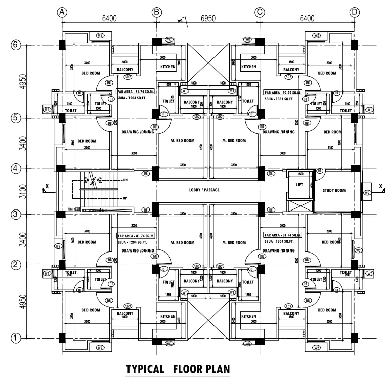
Step 1. Once the architectural drawings were reiceved from the architects the first step is to positioning and orientation of columns and make arrangements of grid line corresponding to it.
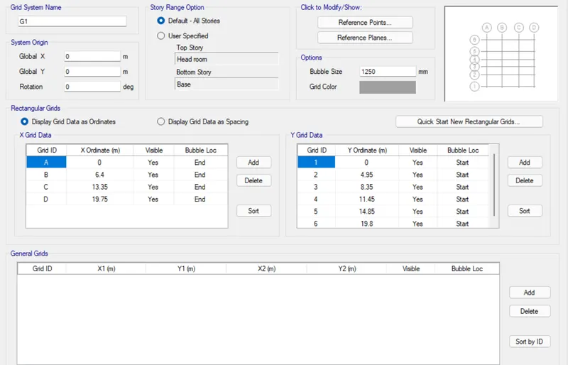
Step 2. Once the columns were finalized the grids were created in the Etabs software to model the structure.
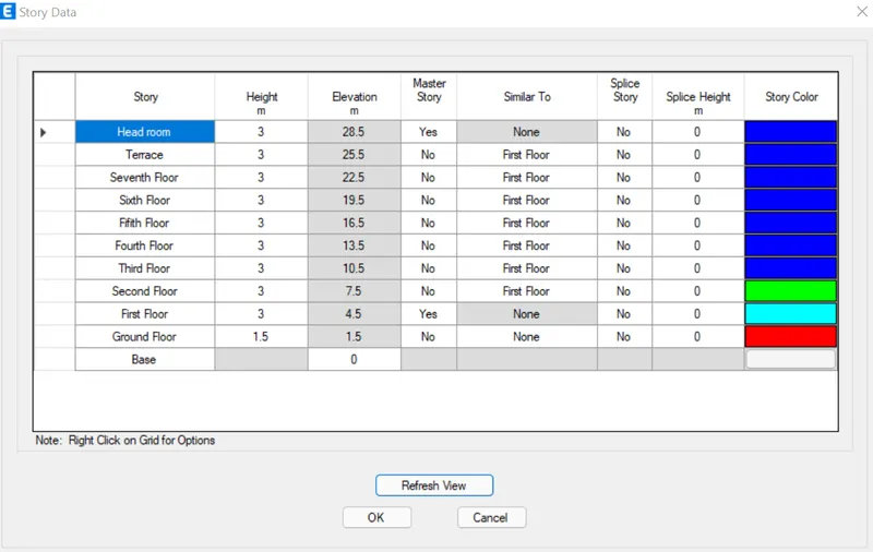
2.1 Material Properties
The Frames were graded with M25 and Fe 500 for Fexural reinforcement and Fe 415 for shear reinforcement
2.2 Frame Properties
The beam size of 300x 450 mm is used throughout the structure. Two different column sizes of C300x 500 for exterior columns and C300x600 for all other interiors columns were defined.The slab for 125mm thick is provided and 150mm thickness for Staircase area. The shear wall of 300 thickness with minimum dimnsion of 1500 length is provide initially. Once all the
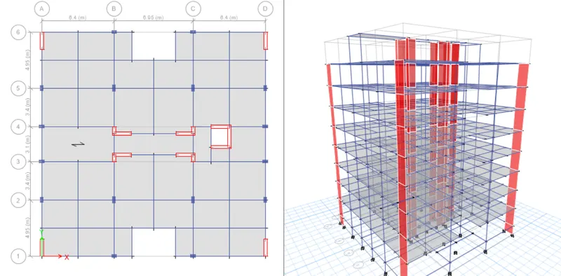
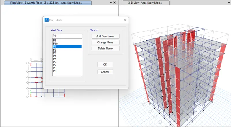
Define Pier label and assigning
2.3 Define Loads and Load Combinations
The Loads were defined in load patterns.
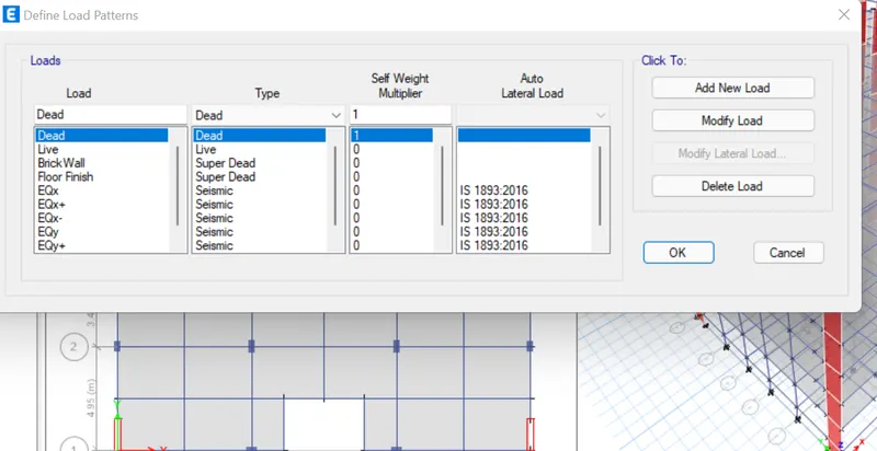
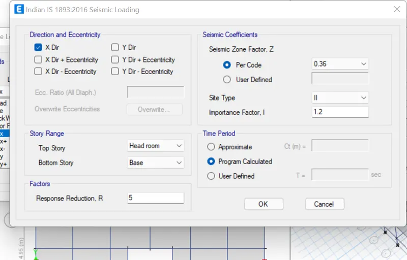
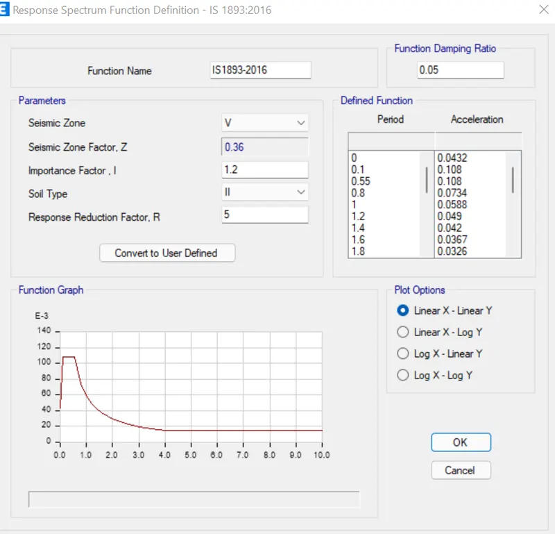
The structure is located at Zone V and the seismic parameter were given according to IS 1893:2016.
Go to Define--> Load Pattern--> Select EQx-->Modify Lateral Load and give the inputs
2.4 Define Mass Source
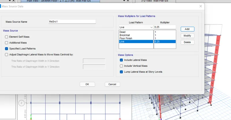
According to IS 1893-2016 the live load of upto 3kN/m^2 the load factor of 0.25 shoild be given
Go to Define--> Mass Source-->MrSrc1---> Modify Mass Source--->Live Load as 0.25
2.5 Define Modal Case
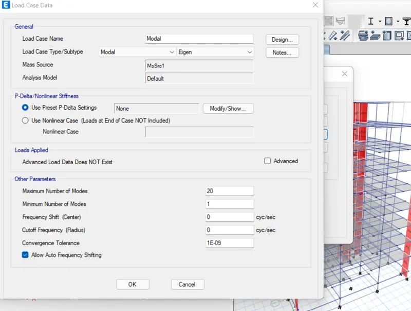
Go to Define--> Load case-->Select Modal-->Modify/Show-->For seismic the maximum number of mass assigned as 20.
2.6 Define Response Spectrum
Go to Define-->Function-->Add New Function
3 Assign of Load and Load Combination
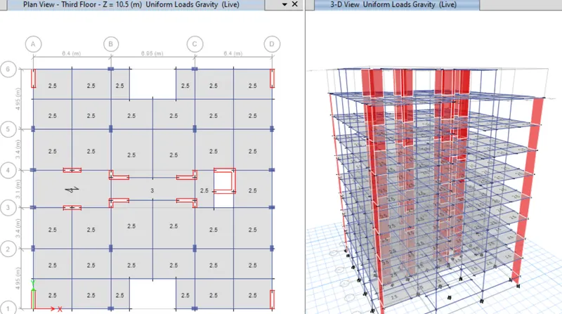
The Live load - 2.5 kN/m^2 common to all floors and 3 kN/m^2 for Staircase and Passage area
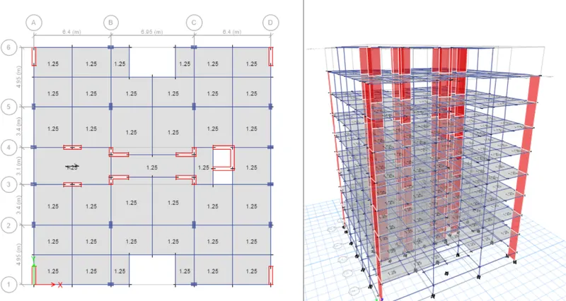
The floor Finish of 1.25kN/m^2
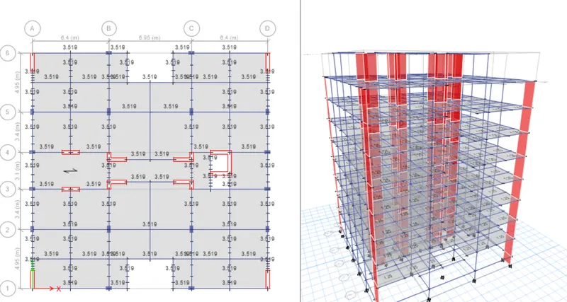
The AAC wall is 3.519kN/m^2 ia assigned
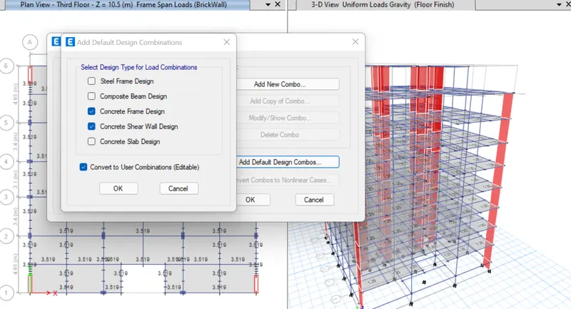
For Load Combination --> Go to Define-->Load Combination-->Add Default Design combos-->Select Concrete Frame and SHear wall Design
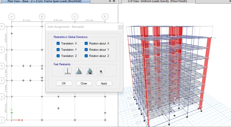
4. Assigning Support Condition
The Support is assigned as Fixed which is restraints in all the directions.
5. Analysis
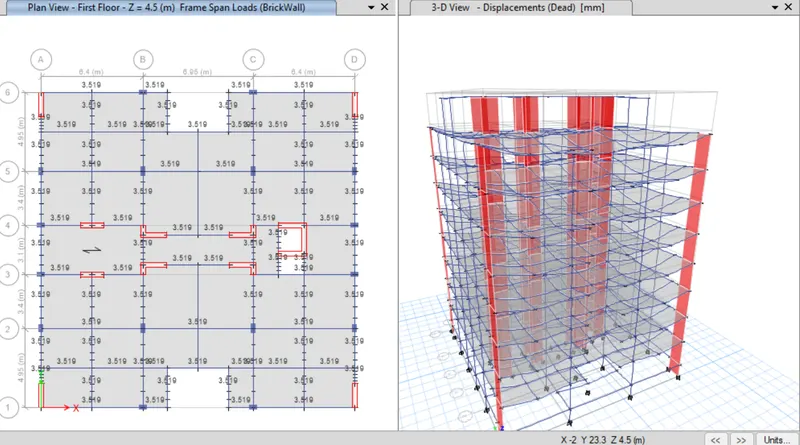
Once the models and all loads were assigned check model and then run the analysis.
6.Results and Discussion
Modal Participation ratio
Go to Display--> Tables-->Analysis Result--> Structure Output-->Modal participation ratio
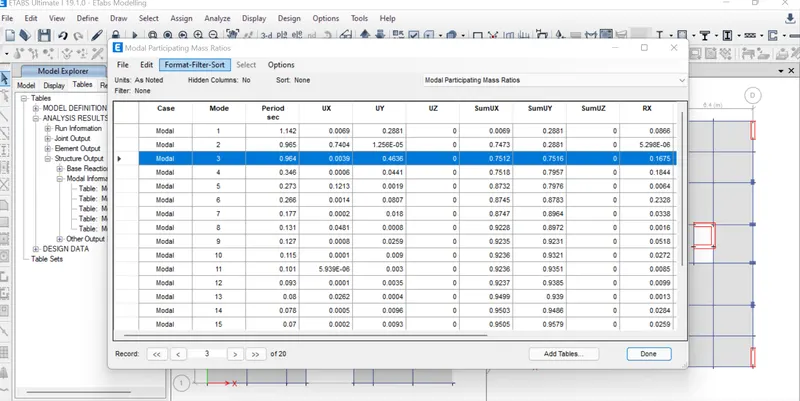
The torsional mode Modal 3 should be less than that of first two modes,therefore satisfied.
Base Reaction
Display-->Tables-->Analysis results-->Base reactions
The base reaction of the base level has be caluclated. Initially define Load Case Add Rsx and RSy and keep scale factor as default.
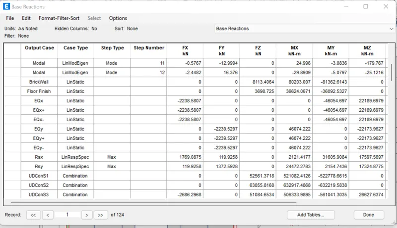
As we need to incresae the base shear in response spectrum load case which is equal to atleast equal to EQx value.
Based on the scale factor which we get will divide by EQx/Rsx which the factor is modified
Go to Define--> Load Case--> Response Spectrum modal case--> update the scale factor and re analysis
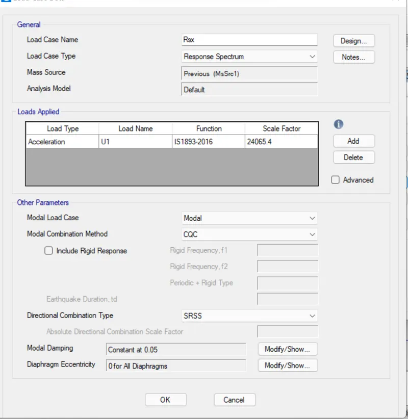
The case should be modified for the case EQy also as same. Once redefine the scale for both direction go for re analysis and check the base reaction.
Therefore the EQx=RSx which is almost equal to 2246.67
Since the purpose Eqx is over the load case is removed from the load pattern
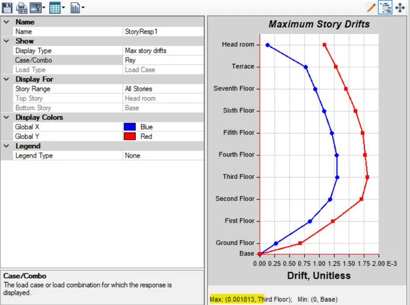
Inter Storey Drift
According to IS 1893:2016 the storey drift should be less than 0.004
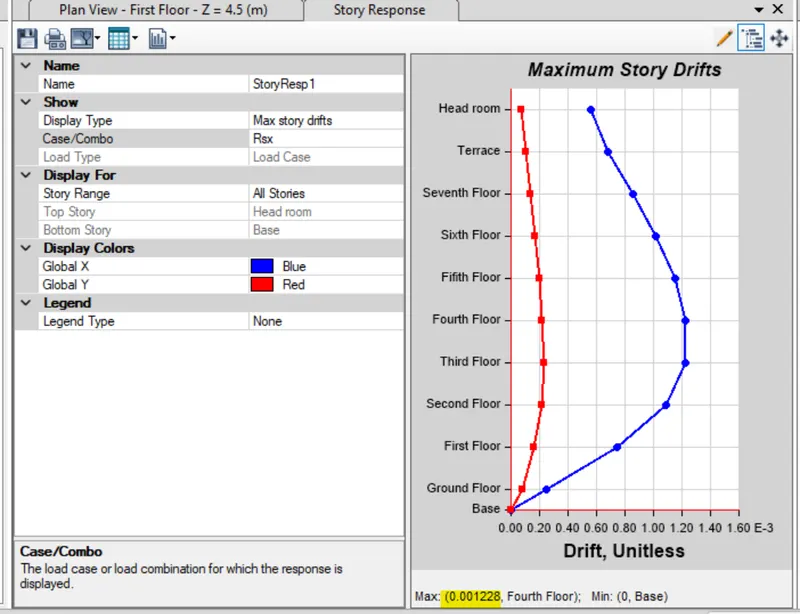
Go to Display--> Storey response plot (RSx) -->0.001228 which is less than 0.004 Hence satisfies Similarily for the RSy--> 0.0018
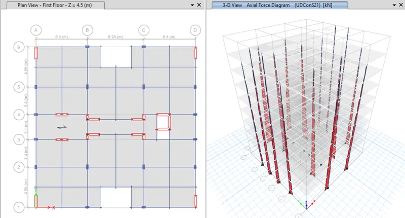
Force Stress Diagram
The base force of the column stress is ensured with compressive forces in all combination
Go to Display-->Force Stress Diagram-->Frame/Pier/Link/forces
Go to Display-->Force Stress Diagram-->Shell Stress/force
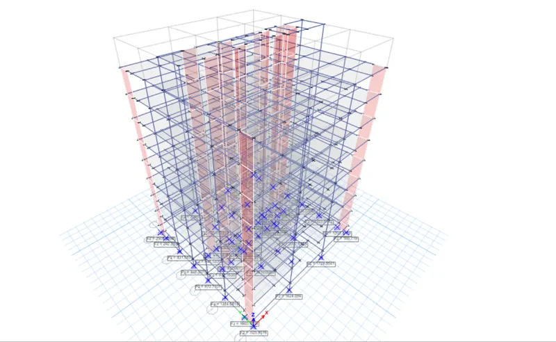
The base compressive stresses of the RC wall is ensured with compressive limit is 0.28fck
Conclusion
Thus the given structural model has been done and verified with seismic criteria as per standards.