Calculation of Stiffness in Structural elements
Qn1. Compute lateral stiffness of the one story frame with an intermediate realistic stiffness of the beam. The system has 3 DOFs as shown. Assume L = 2h and Elb = Elc
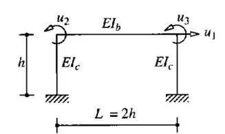
Ans. As the System has three degrees of freedom.
By using Stiffness coefficient matrix
The element of stiffness at (ki1) can be computed using the condition u1=1, u2=u3=0
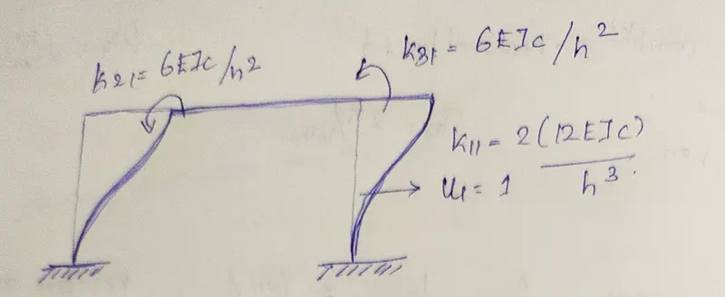
The stiffness coefficient of column translation = 2 x (12 EIC/h^3)
The stiffness co efficient of Beam rotation at 2 ends become EIC/h^2
Similarly the element of stiffness at (ki2) on the second column using the condition u2=1 , u1=u3=0
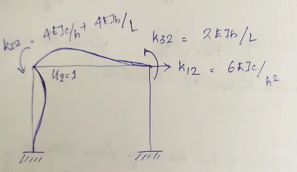
The stiffness coefficient of column rotation at right end of the beam 6EIb/h^2
The stiffness coefficient of column rotation and left end of the beam
4EIc/h + 4EIb/L where L = 2h and the second moment of inertia on beam and column are equal
then it can be written as 4EI/h + 4EI/2h = 6EI/h
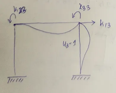
The stiffness coefficient of column rotation at left end of the beam 6EIb/h2
The stiffness coefficient of column rotation and right end of the beam
4EIc/h + 4EIb/L where L = 2h and the second moment of inertia on beam and column are equal
then it can be written as 4EI/h + 4EI/2h = 6EI/h
Thus the stiffness matrix of the structure can be determined by using the equation fs= k.u
`(EIc)/h^3`=`[[24,6h,6h],[6h,6h^2,h^2],[6h,h^2,6h^2]]`* `((u1),(u2),(u3))`=`((fs),(0),(0))`---Eqn 1
From the second and third equations, the joint rotations can be expressed in terms of lateral displacement as follows.
`((u2),(u3))= -[[6h^2,h^2],[h^2,6h^2]]^-1 ((6h),(6h)) u_1 = -6/(7h)[[1],[1]]u_1`-----Eqn 2
Substitue Eqn 2 in Eqn 1 we get it as
`f_s=((24EI_c)/h^3,-(EI_c)/h^3,6/(7h) ((6h,6h))[[1],[1]]u_1`
Therefore, the lateral stiffness of the frame is
`f_s=96/7(EI_c)/h^3`
Question 2 a
For the following structures:
- Determine the number of degrees-of-freedom for dynamic analysis
- Establish the equation of motion
- Calculate their natural frequencies
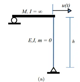
(i) The number of degrees of freedom for the dynamic analysis is 1
(ii) The equation of motion shall be as
`mddotu+ku=0`
The stiffness coefficient of the above fig as `k= (3EI)/h^3`
By substitution the equation of motion is written as
`mddotu+[(3EI)/h^3] u=0`
(iii) The naturalfrequency ɷ=√(k/m)
`root . (3EI)/(mh^3)`
Question 2 b.
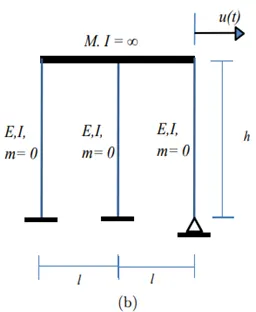
(i) The number of degrees of freedom for dynamic analysis is 1
(ii) The equation of motion shall be as
(ii) The equation of motion shall be as
`mddotu+ku=0`
In the above figure the two columns ends were fixed and one column has pinned support
The stiffness coefficient at fixed end conditions as say =`k_1=k_2=(12EI)/h^3``
The stiffness coefficient at pinned end condition as `k_3=(3EI)/h^3`
As the stiffness element were arranged in parallel
total stiffness `k=k_1+ k_2+k_3`= `(EI)/h^3[ 12+12+3]= (27 EI)/h^3`
`therefore` by substituting the value of k in equation of motion.
`mddotu+(27 EI)/h^3`u=0`
`The natural frequency ɷ=√(k/m) = (√27EI)/(mh^3)`
Question 3
Question 3:
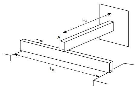
Consider the propped cantilever shown in the figure below. The beams are made from the same steel section and have lengths as shown on the diagram. Determine the natural period of this system if a large mass, M, is placed at the intersection of the beams at point A. The weight of the beams in comparison with the mass M is very small.
The natural frequency `omega_n= sqrt(k/m)`
The lateral stiffness on simply supported beam as `k_1=(48EI)/L_b^3`
The lateral stiffness on cantilever beam as `k_2= (3EI)/(L_c^3)`
Therefore the total stiffness is calculated as k=`k_1+k_2`
k =(48EI)/L_b^3`+(3EI)/(L_c^3)`
k = `3EI((16)/(L_b^3)+ 1/L_c^3)`
Therefore the natural frequency `omega_n= root*(k/m)`
`sqrt (3EI((16)/(L_b^3)+ 1/L_c^3))/sqrt M`
The natural period Tn=`(2pi)/omega_n`
= `(2pi * sqrtM)/sqrt(3EI(1/L_c^3+1/L_b^3)`
Question 4 (a)
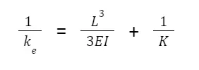
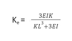
Determine an expression for the effective stiffness of the following systems
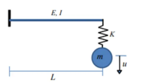
The stiffness coefficient is
``k=(3EI)/h^3`
The stiffness are arrangment as in series
therefore
Question 4(b)
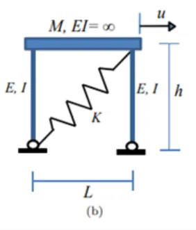
The stiffness coefficient k as (3EI)/h^3`
The stiffness coefficient of the spring is K act as inclined
Inclined component of load P= p/cosѲ
Inclined component of deformation u = u cosѲ
Stiffness coefficient of spring K = p / u `Cos^2 theta`
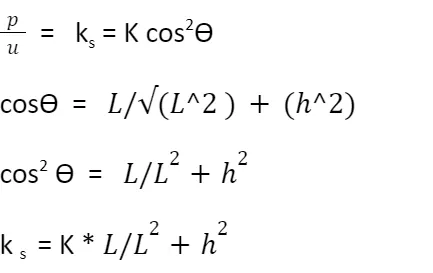
The effective stiffness of the system
`k_e= (6EI)/h^3+ (KL^2)/L^2+h^2`
Question 4 (c)
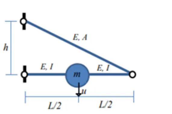
The stiffness of the element is supported as pinned support therfore,
`k_1= (48EI)/L^3`
As effective stiffness coefficient for the system has to be formed in addition to the relative axial stiffness provided by the inclined strut connected.
`(mg)/2 = kea,vert x 2 x `Delta_2`
`(mg)/Delta_2 =`4 kea,vert
`k_2=`4 kea,vert
Inorder to solve the inclined axial stiffness, the kea,vert is resolved as
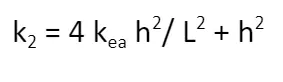
As the stiffness arrangement are in terms of series.
`1/k_e=1/k_1+1/k_2`
Substitute the value of `k_1 and K_2` in the above equation we get
`k_e= ((4AEh^2)/(L^2+h^2)^(3/2)) (48EI)/L^3/((4AEh^2)/(L^2+h^2)^(3/2)+(48EI)/L^3)`