Structural Modelling using Etabs 2018
Aim: To Run a modal response spectrum analysis and check analysis results of the etabs model for inter-storey drift requirements, vertical & planar irregularities, minimum shear wall requirements,maximum axial load ratio for column and shear walls, effective moment of inertia for beams and columns as per the IS 1893 and IS 13920 for a G+7 residential building in zone 5
Procedure:
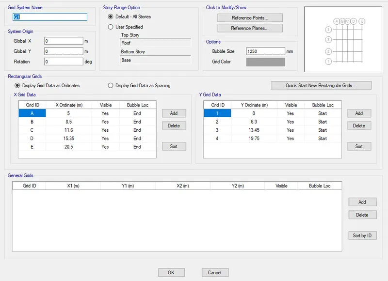
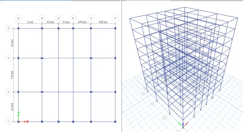
1. Opening the Etabs and setting the grid pattern and the height of the building
 '
'
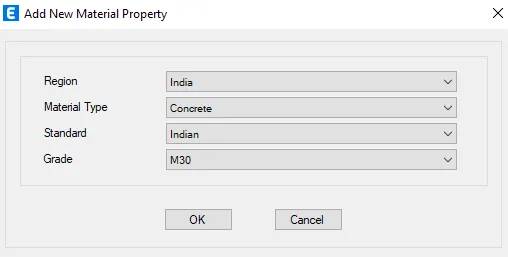
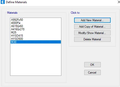
2. Defining the material Properties
a) Defining the M25 Concrete
b) Defining the M30 Concrete
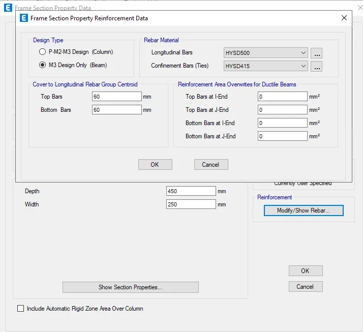
c) Defining the Fe500 steel for main reinforcement
d) Defining the Fe 415 steel for Stirrups
3. Defining the Section properties, Slab properties and the wall Properties.
a) Defining the Beam of 300X450mm
b) Defining the column of 400X400mm
c) Defining the column of 300X550mm
d) Defining the slab of 200mm
e) Defining the Slab in staircase section with one way load distribution of 250mm
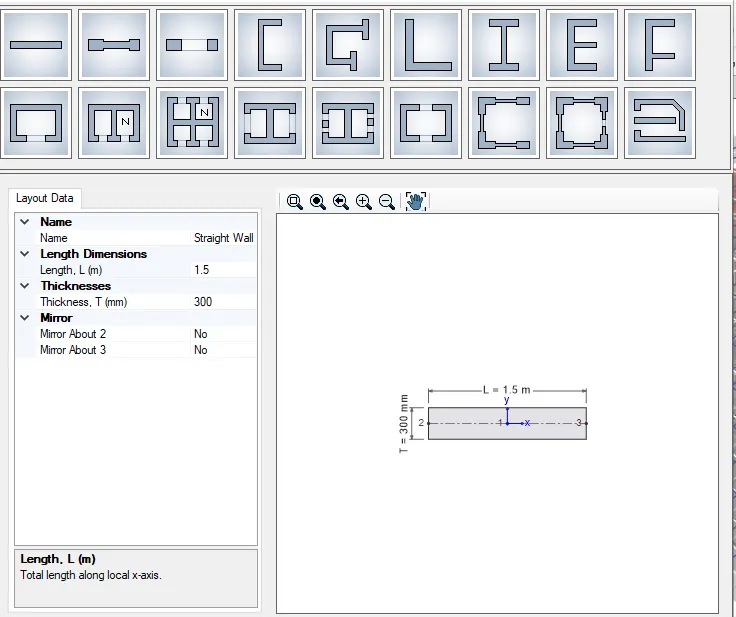
f) Defining the Shear wall of 300mm
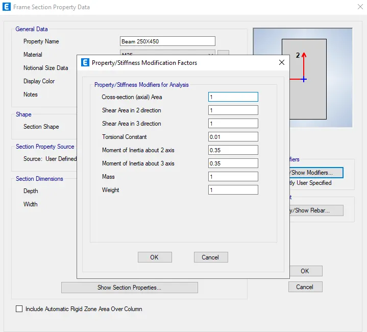
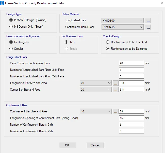
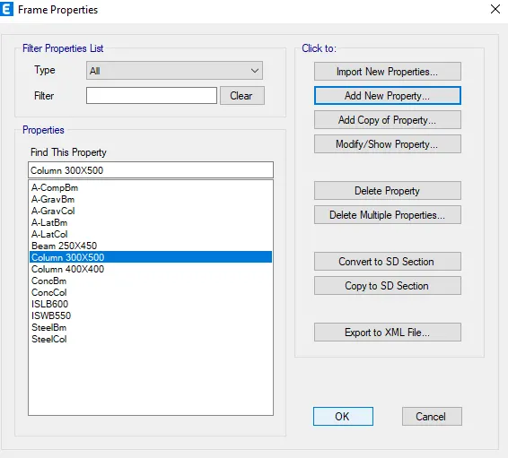
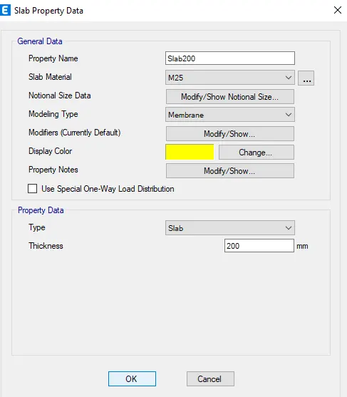
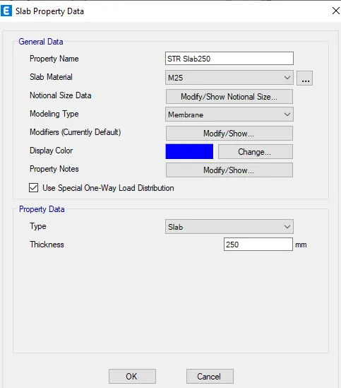
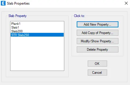
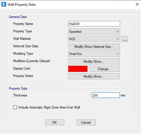
4. Placing the defined columns at the joint and the beams on the positions.
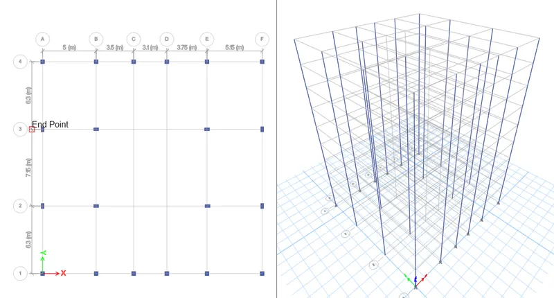
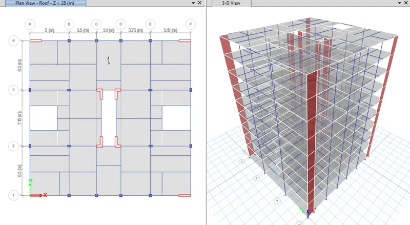
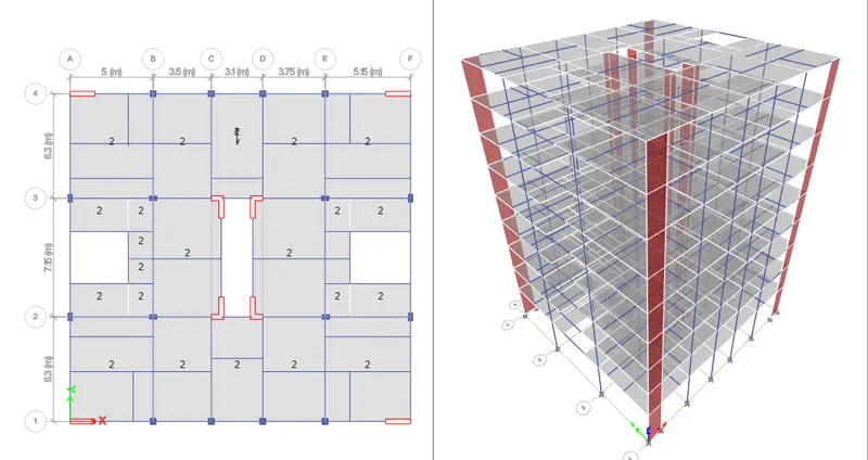
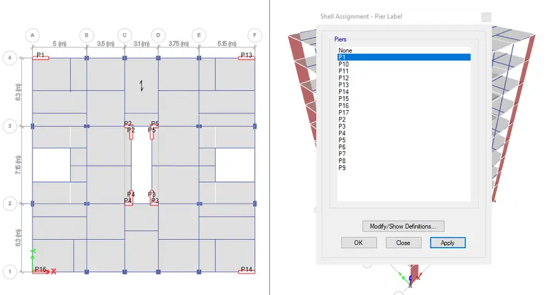
5. Adding the shear wall of 300mm on the corner of the apartment on the X axis grid and also adding the secondary beams as shown in the figure
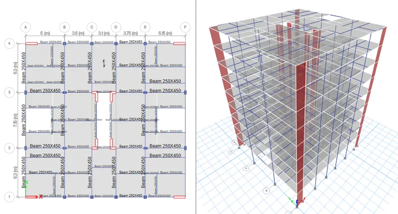
6. Adiing the slab of 200mm on the building and the Staircase slab of 250mm on the staircase area.
7. Defining the loads
a) Defining the dead load
b) Defining the Live load of 2 kN/m2
c) Defiming the brickwall load of 3.5 kN/m2
d) Defining the Floor finishes load of 1.2kN/m2
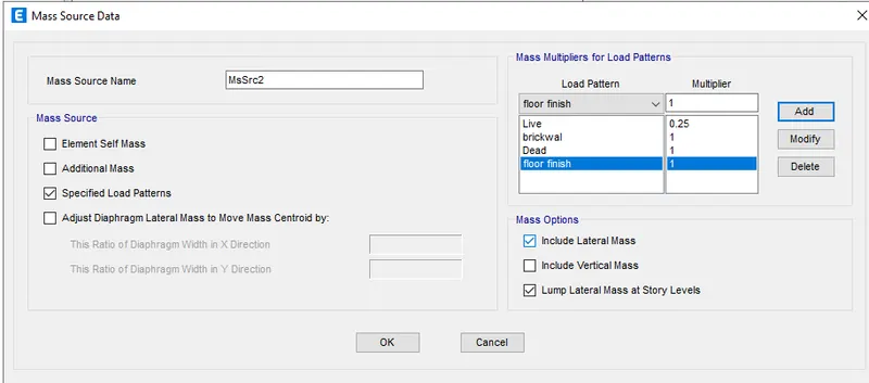
8. Applying the defined loads to the building the building
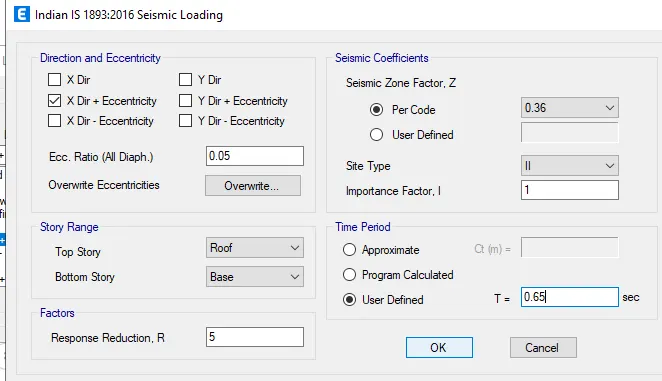
9. Defining the Earthquake loads
a) Defining the EQ load in X direction.
b) Defining the EQ load in X+ direction.
c) Defining the EQ load in X- direction.
d) Defining the EQ load in Y direction.
e) Defining the EQ load in Y+ direction.
f) Defining the EQ load in Y- direction.
10. Defining the Diapragh to the building
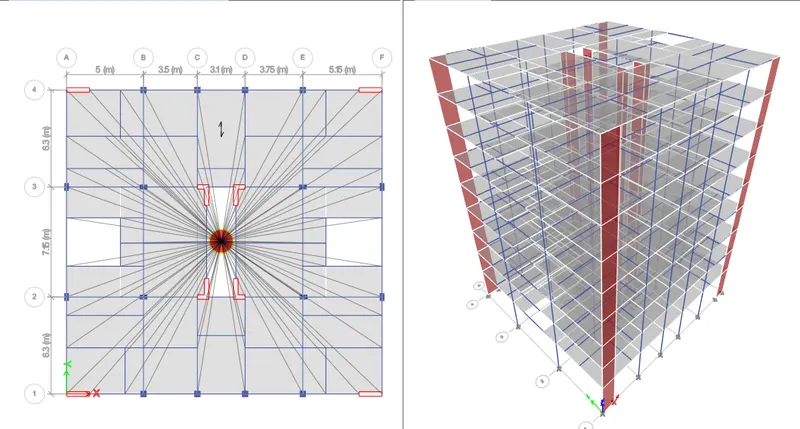
12. The Shear wall are pier named with appropriate number
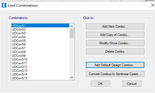
13.Defining the load Combinations along with the mass source and also the mass source value to 20
14. Checing for the warning and the error in the building

15. Adding the Load Cases with the response spectrum in both X and Y direction
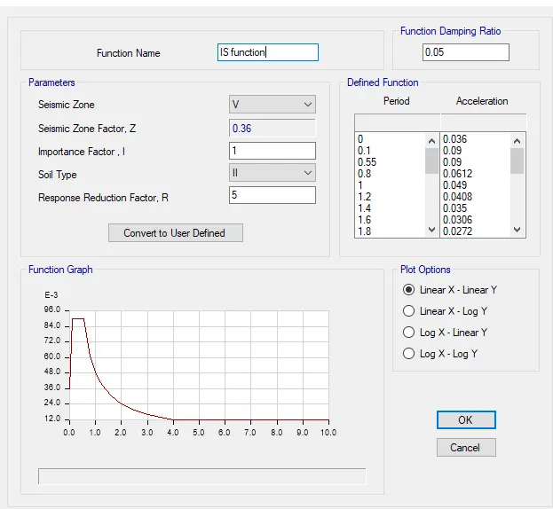
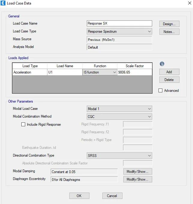
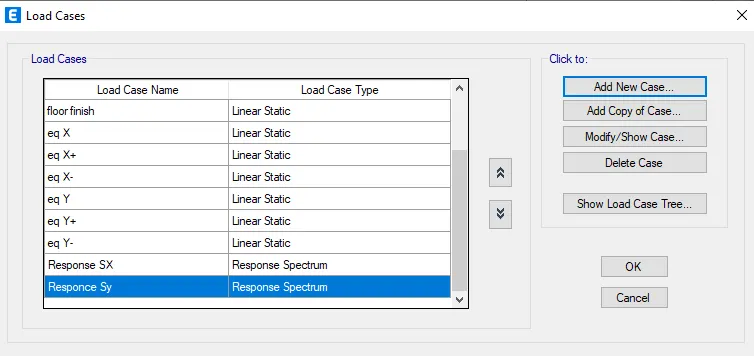
16. Run the Analysis
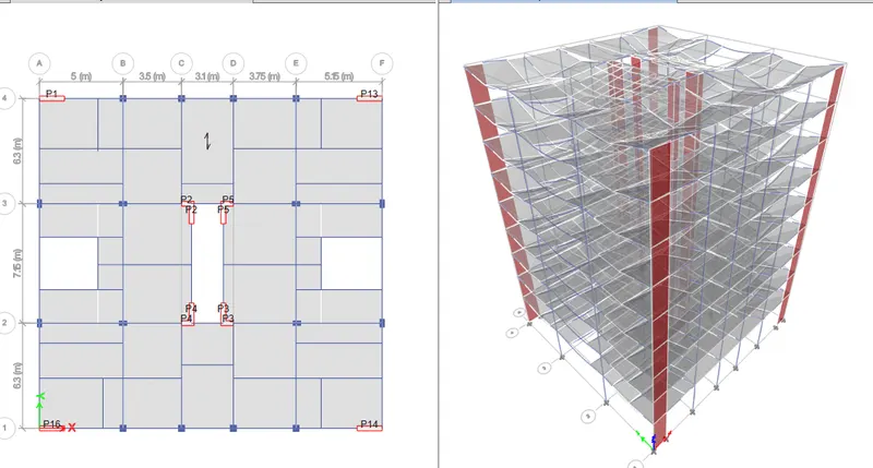
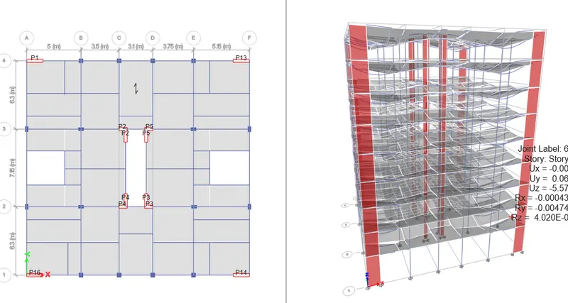
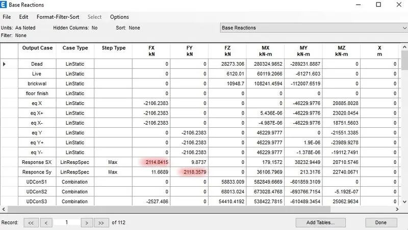
17. Checking the Base reactions after running the analysis
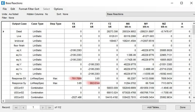
Correcting the Responce spectrum in X and Y direction by correcting the scale factor
Responce spectrum in X = [(2110/780)X9806.65] = 26528.25
Responce spectrum in X = [(2110/660)X9806.65] = 31351.56
Base reactions after entering the corrected scale factors
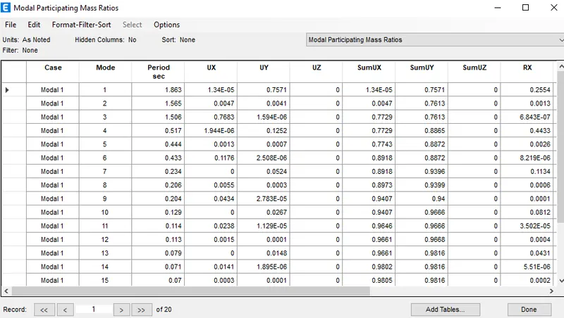
18. Dispalying the modal mass participating ratio
whereas 12 modal are sufficient which shows the 95% mass ratio in X,Y and Z direction
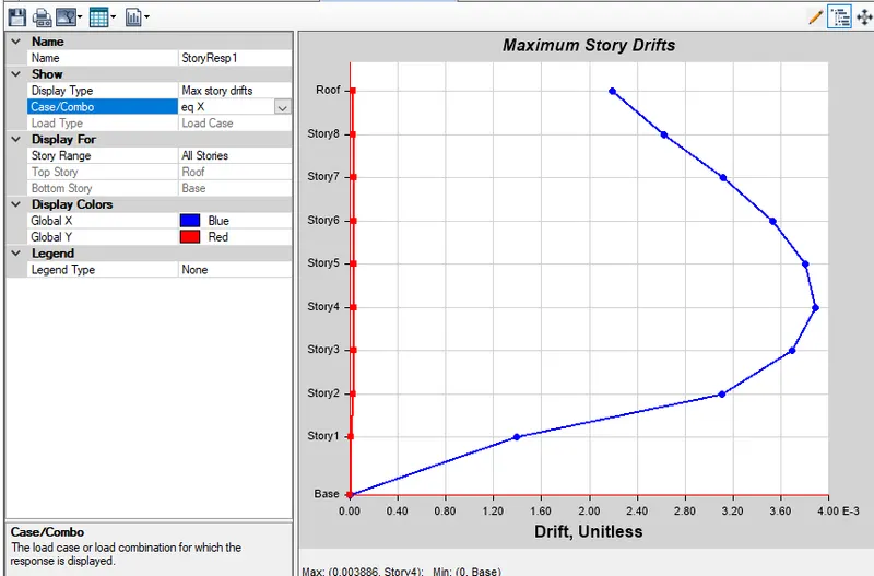
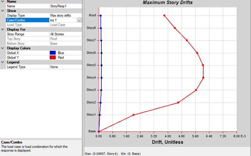
19. Displaying the maximum drift in EQ X direction and Y direction
20. Checking the Horizontal and vertical loads
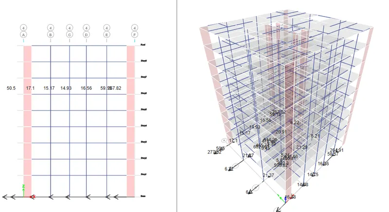
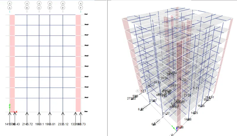
Checking for the Failure of the column from the maximum vertical load
here max vertical load is 2335.12kN
= [Maximum reaction/(Column size X fck)]
= [(2335.12X1000)/(400X400X30)]= 0.48 > 0.4 ( From IS code 13920 and IS 1893)
so the dimension of the column is increase or the fck of the concrete is increased
Also checking the Wall shear failure will is safe
21. Changing the column size to 500X 500 mm and fck as 30Mpa
= [(2335.12X1000)/(500X500X30)]= 0.31 < 0.4 ( safe)
22. Hence the Analysis is successfull meeting all the requirements.