Structural Modelling using Etabs 2018
Challenge #11 - Structural Modelling using Etabs 2018
Step1: Starting a new model with all relevant Indian standard codes and units as below: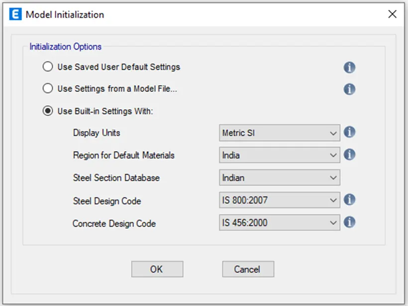
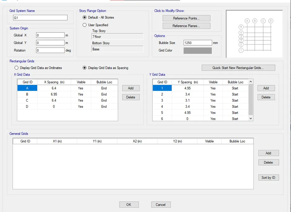
Step 2: Selecting the suitable grid details required for the exercise as below:
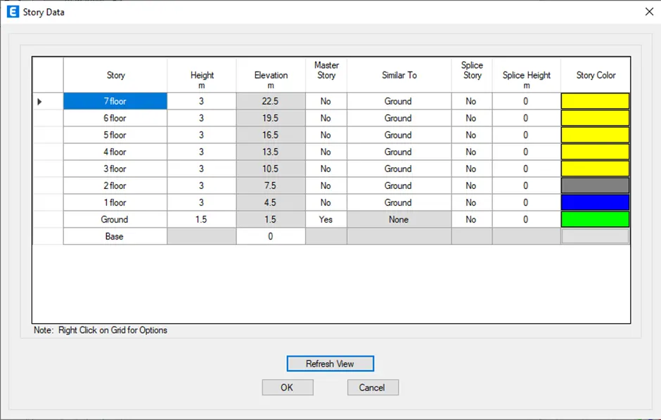
Step 3: Selecting the suitable story details required for the exercise as below:
Step 4: Material properties
Defining M30 grade concrete properties as below:
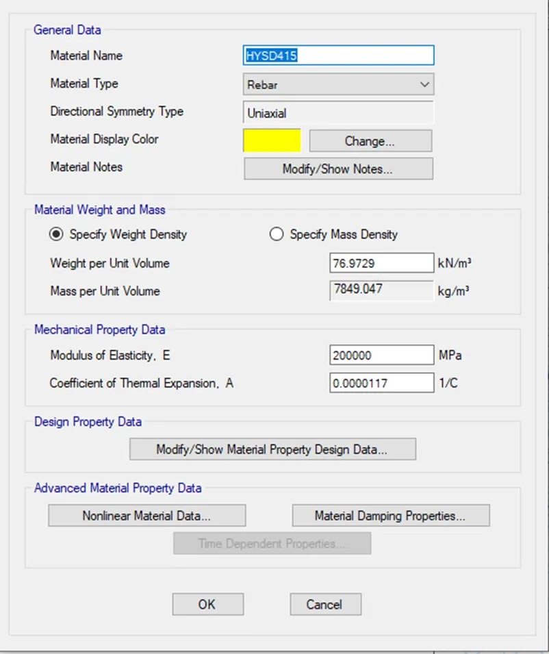
Fe -415 steel properties for confinement rebars as below:
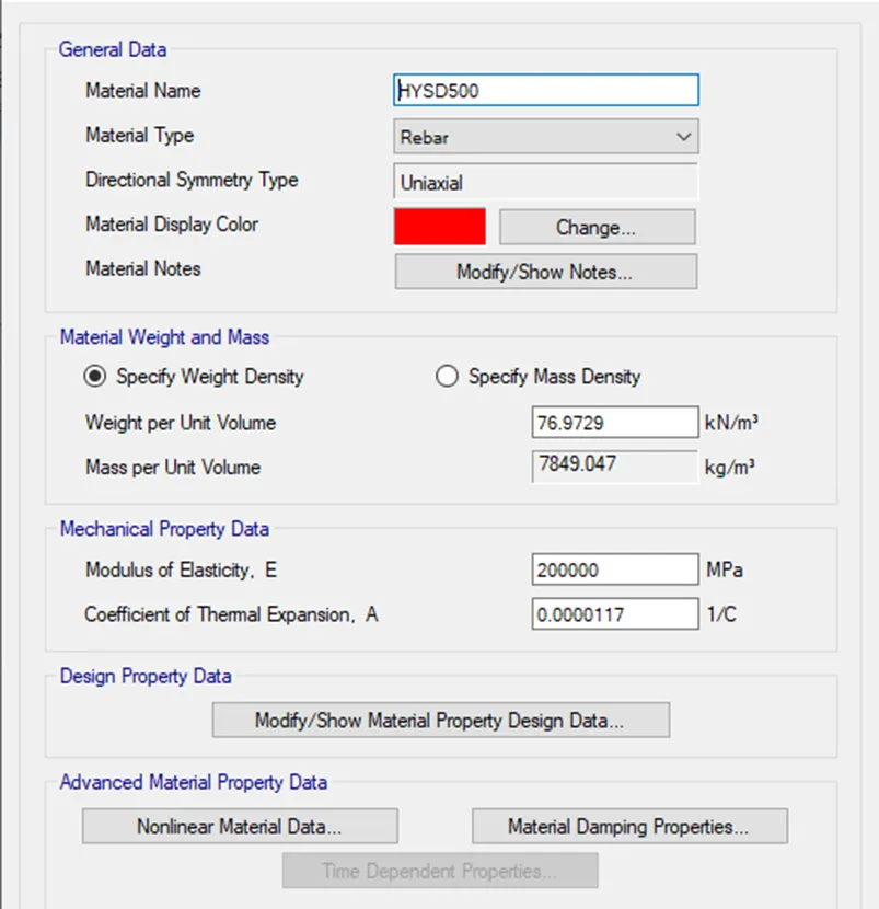
Fe -500 steel for longitudinal rebars properties as below:
Step 5: Section properties
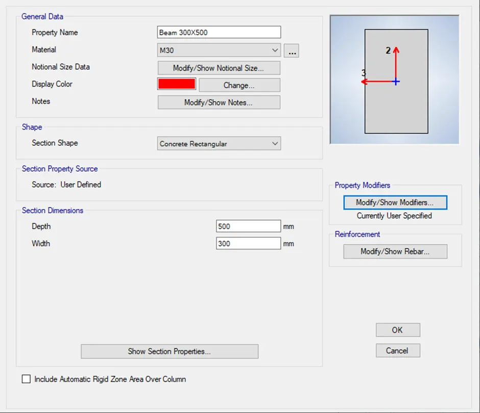
Defining the Beam of Size (300 X 500) mm as below:
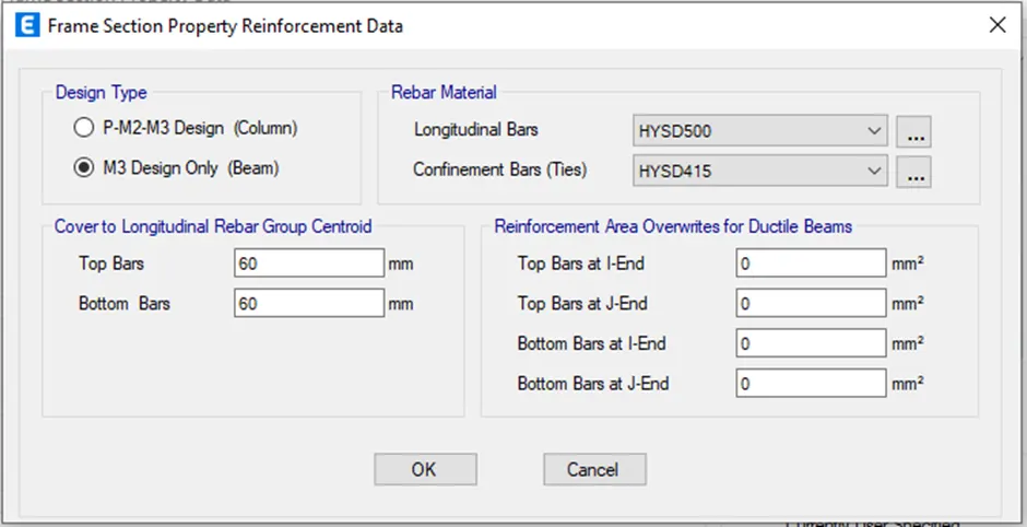
Assigning the beam property to the frame section as below:
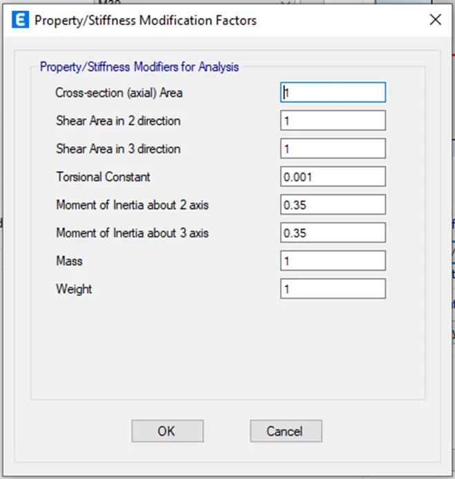
 Modifying the stiffness factors for beam for earthquake forces as below:
Similarly defining the Beam of Size (250 X 450) mm
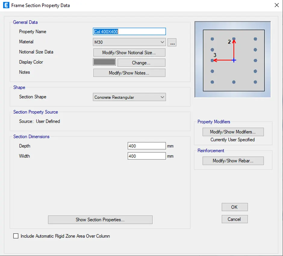
Defining the column of Size (400 X 400) mm as below:
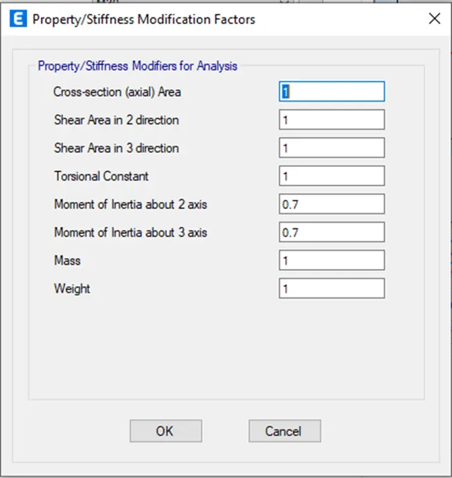
Modifying the stiffness factors for earthquake forces as below:
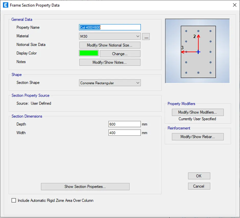
Similarly defining the column of Size (400 X 600) mm as below:
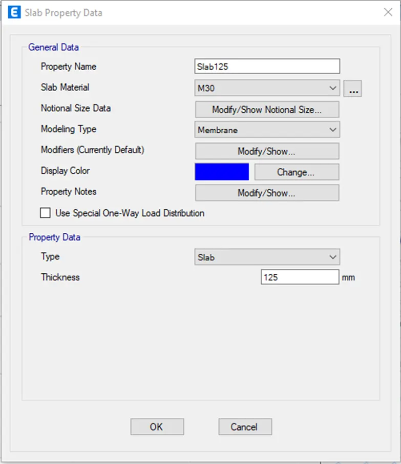
Defining the Slab section of 125 mm as below:
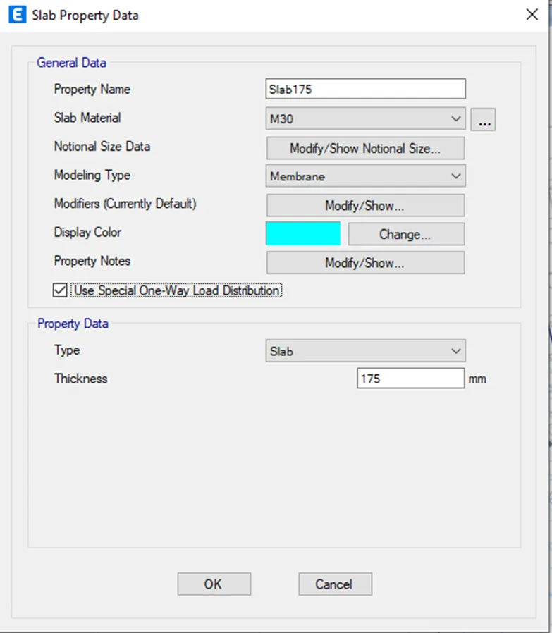
Defining the staircase Slab (one way) section of 175 mm as below:
Defining the Shear Wall of thickness of 300 mm as below: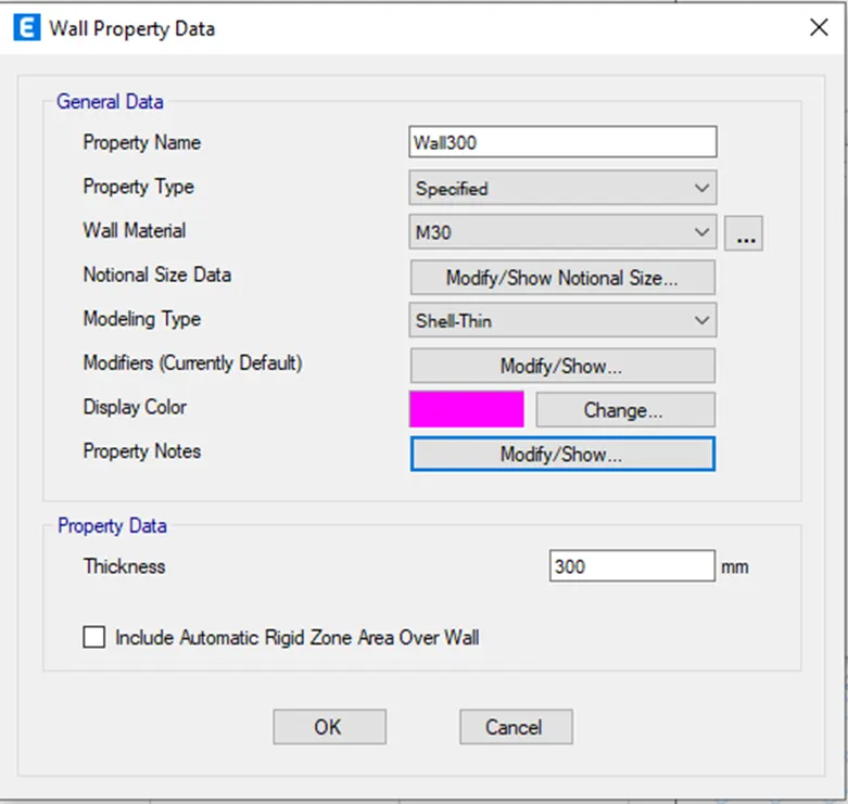
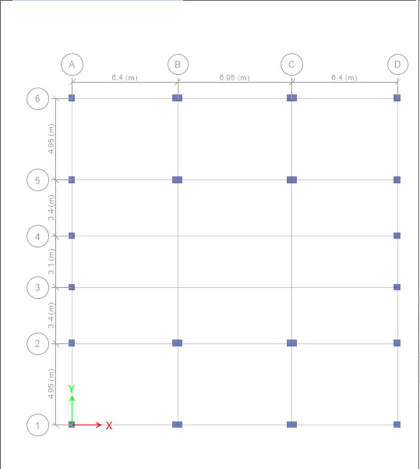
Step 6: Adding the columns using Quick draw columns option from the side menu bar as below:
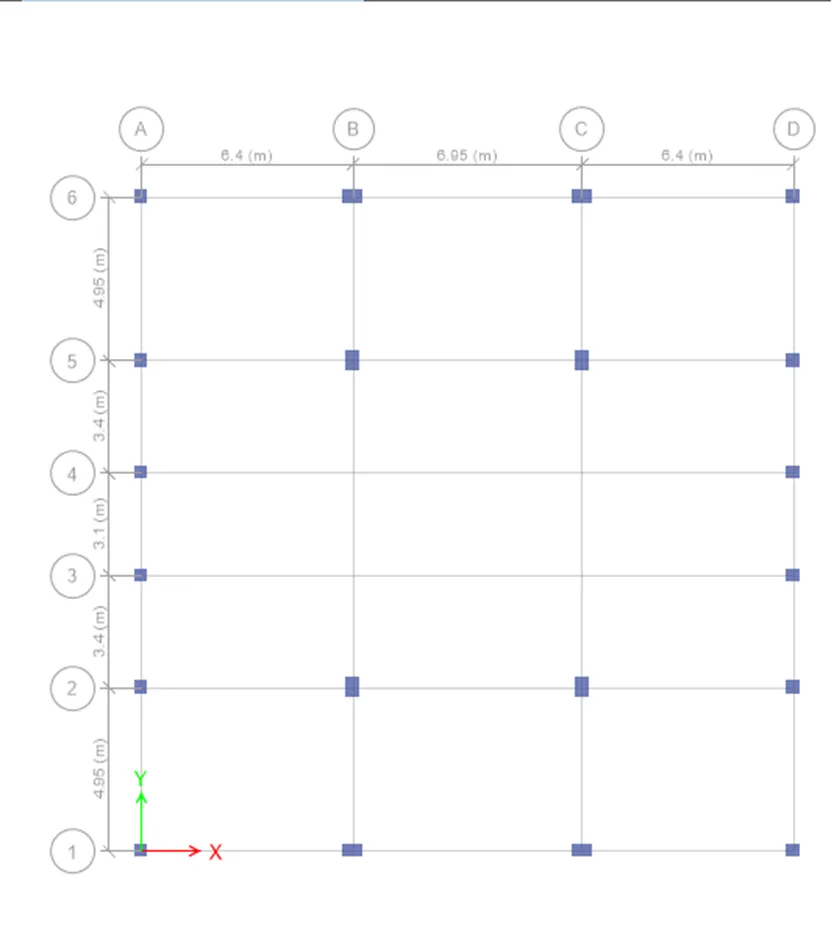
Step 7: Changing the orientation of the interior 4 columns by 90 degree as below:
 Step 8: Adding the beams using Quick draw beams option from the side menu bar as below:
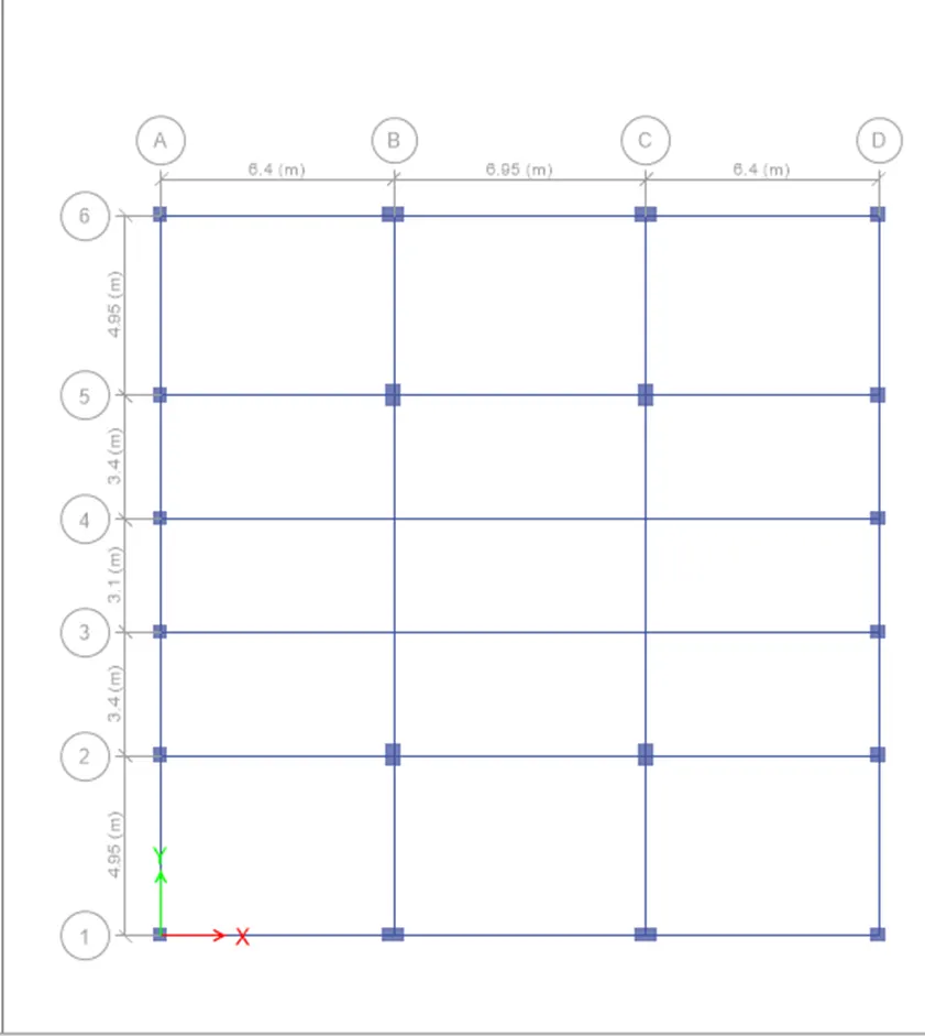
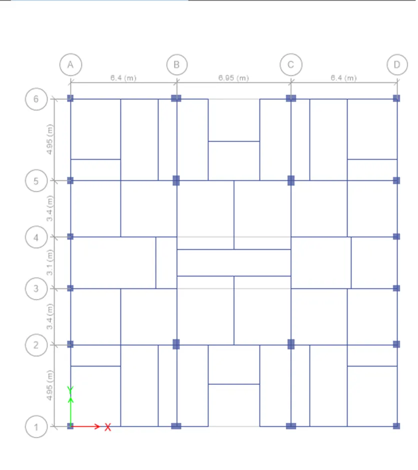
Step 9: Adding secondary beams as below:
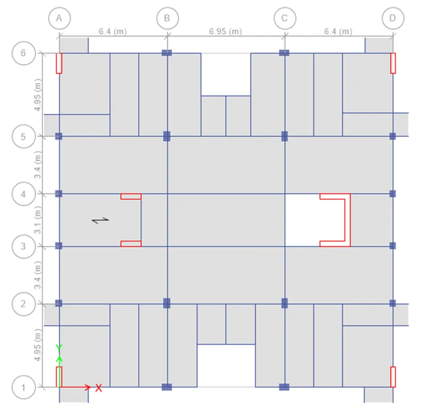
Step 10: Adding shear wall sections as below:
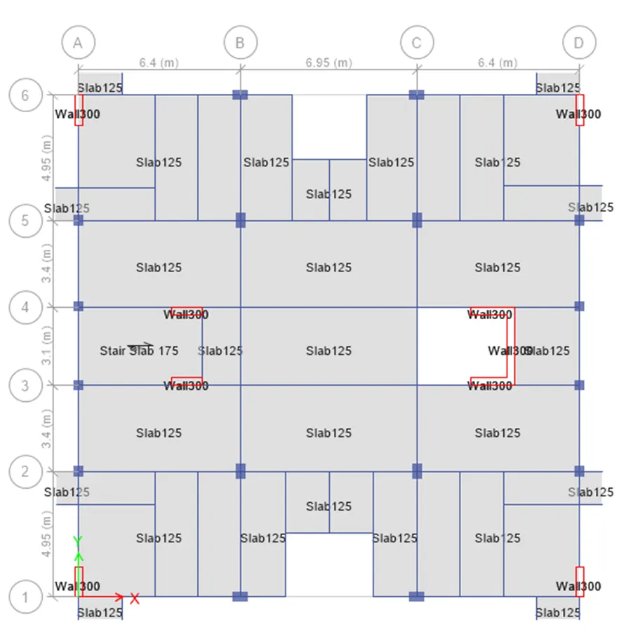
Step 11: Assigning slab sections as below:
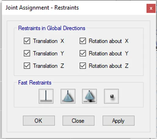
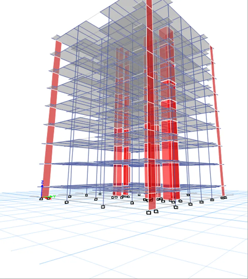
Step 12: Assigning restraints as fixed as below at the base level of all columns:
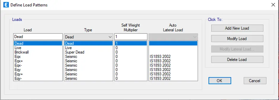
Step 13: Defining load cases as below:
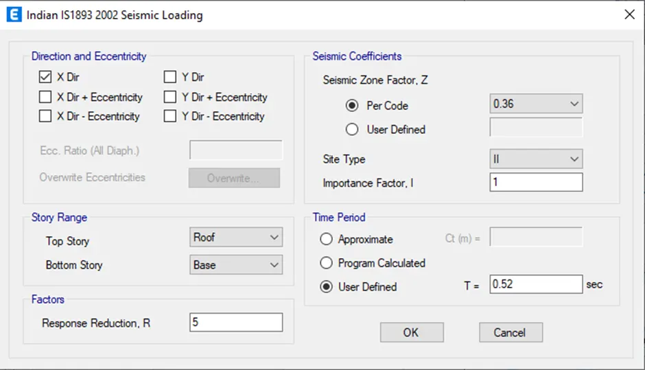
Step 14: Modifying the Earthquake load as below:
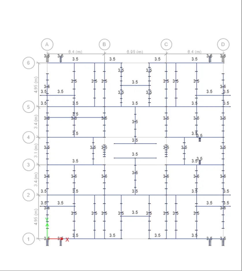
Step 15: Assigning the brickwall load of 3.5 Kn/m (UDL) as below:
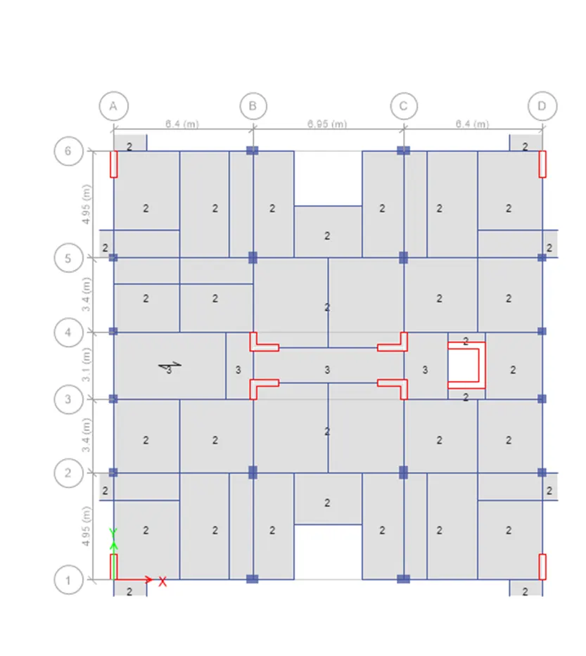
Step 16: Assigning the Shell load of 3 KN/m^2 for staircase, lobby area and 2 KN/m^2 (UDL) for rest of the area as below:
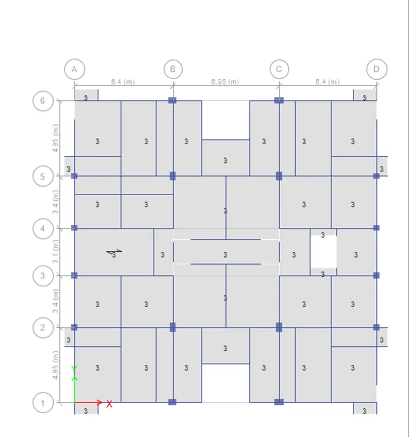
Step 17: Assigning live load of 3KN/m^2 for roof to account for water proofing works on the terrace as below:
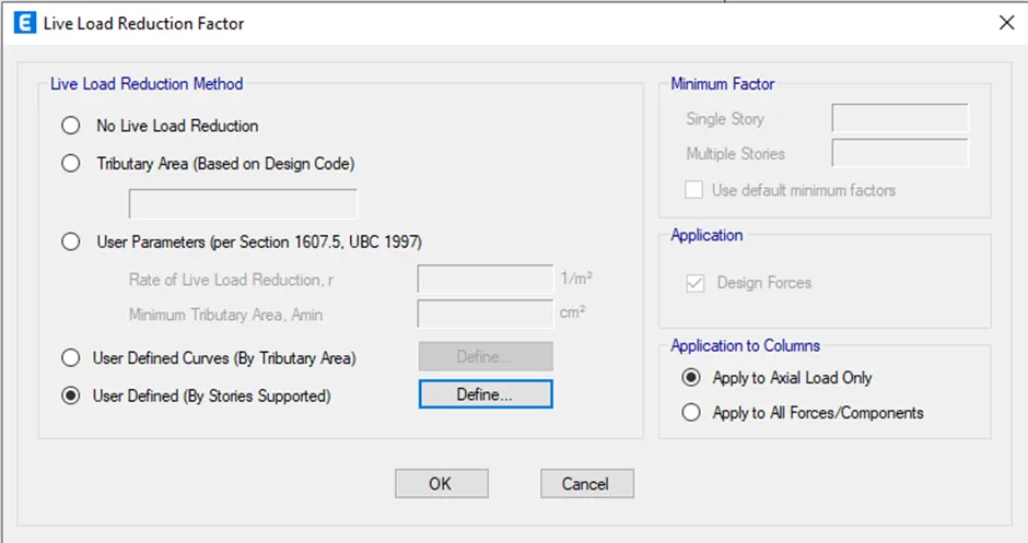
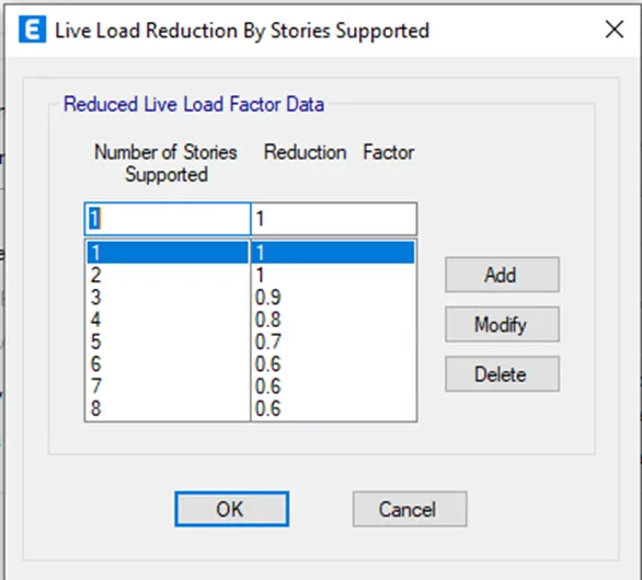
Step 18: Assigning Live load reduction factor:
Step 19: Defining the load cases as below:
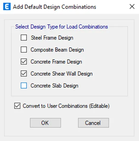
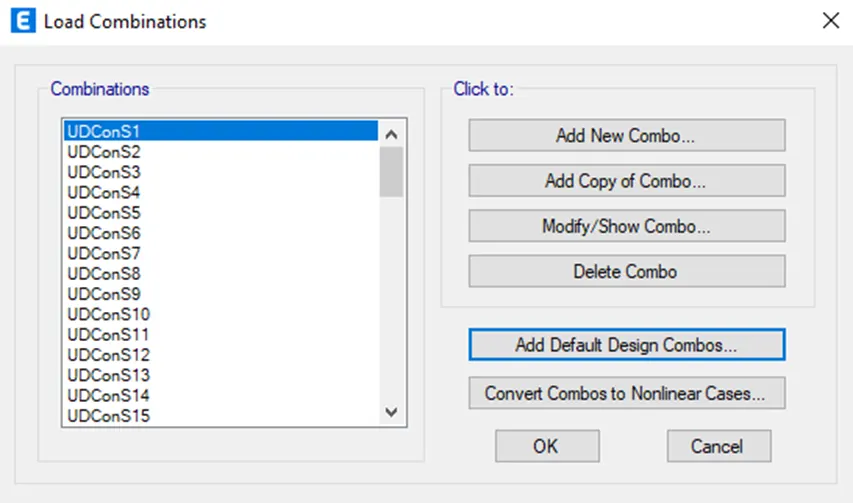
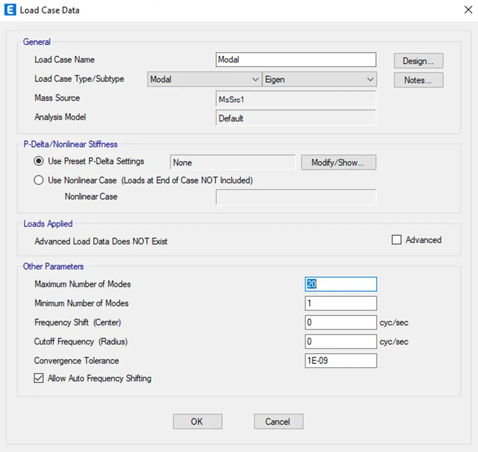
Step 20: Defining Modal Case with no of modes as 20:
Step 21: Defining response spectrum as below:
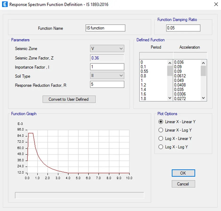
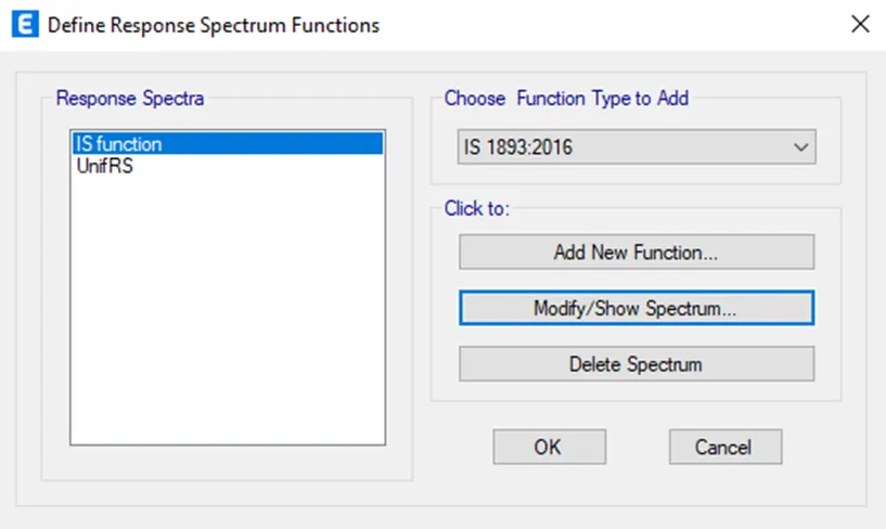
Step 22: Adding load cases of Response spectrum in X & Y directions as below:
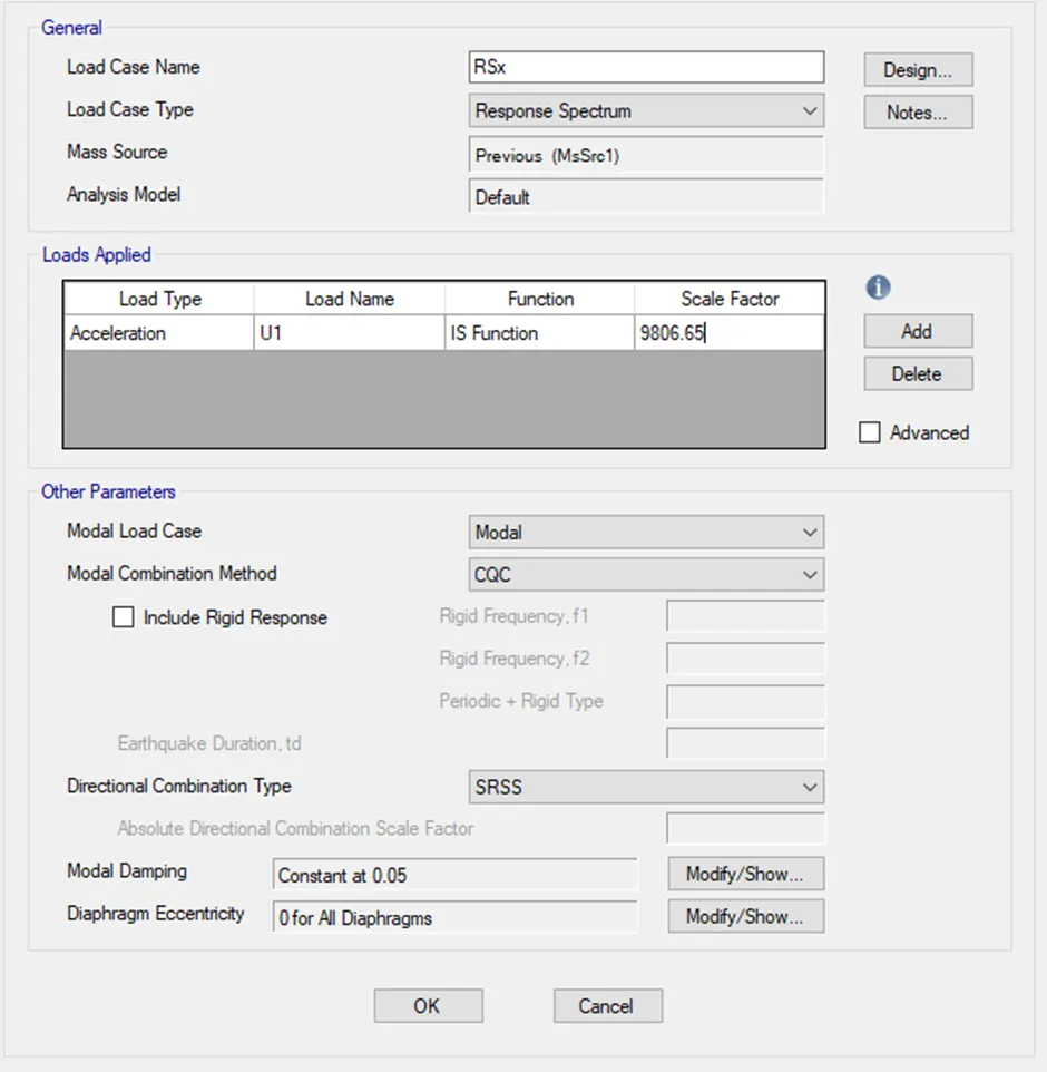
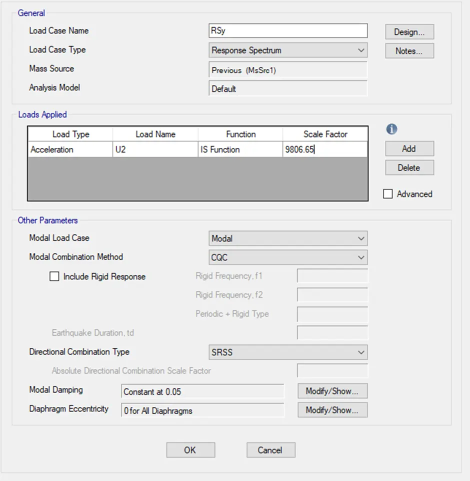
Step 23: After the checking the model for any errors, Run the analysis. Go to display of structural output tables as below:
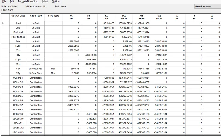
The above results have been obtained after increasing the scale factor. Hence the base reactions in EQx and EQy are equal to the base reactions obtained in the Response spectrum (X & Y).
Step 24: Next, choosing the Modal participating load ratios from the display of structural output tables as below:
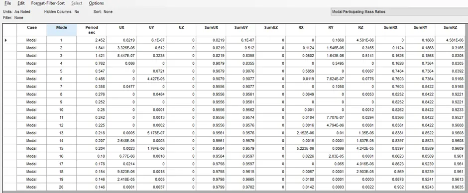
From the table, it can be observed that along X and Y directions initial 6 modes are contributing 90% of modal mass whereas in rotational directions RX & RY, 20th mode is satisfying the min. criteria of 90%. Hence for RX & RY directions all 20 modes are essential.
Step 25: Obtaining Story response plots from the Display option, as below.
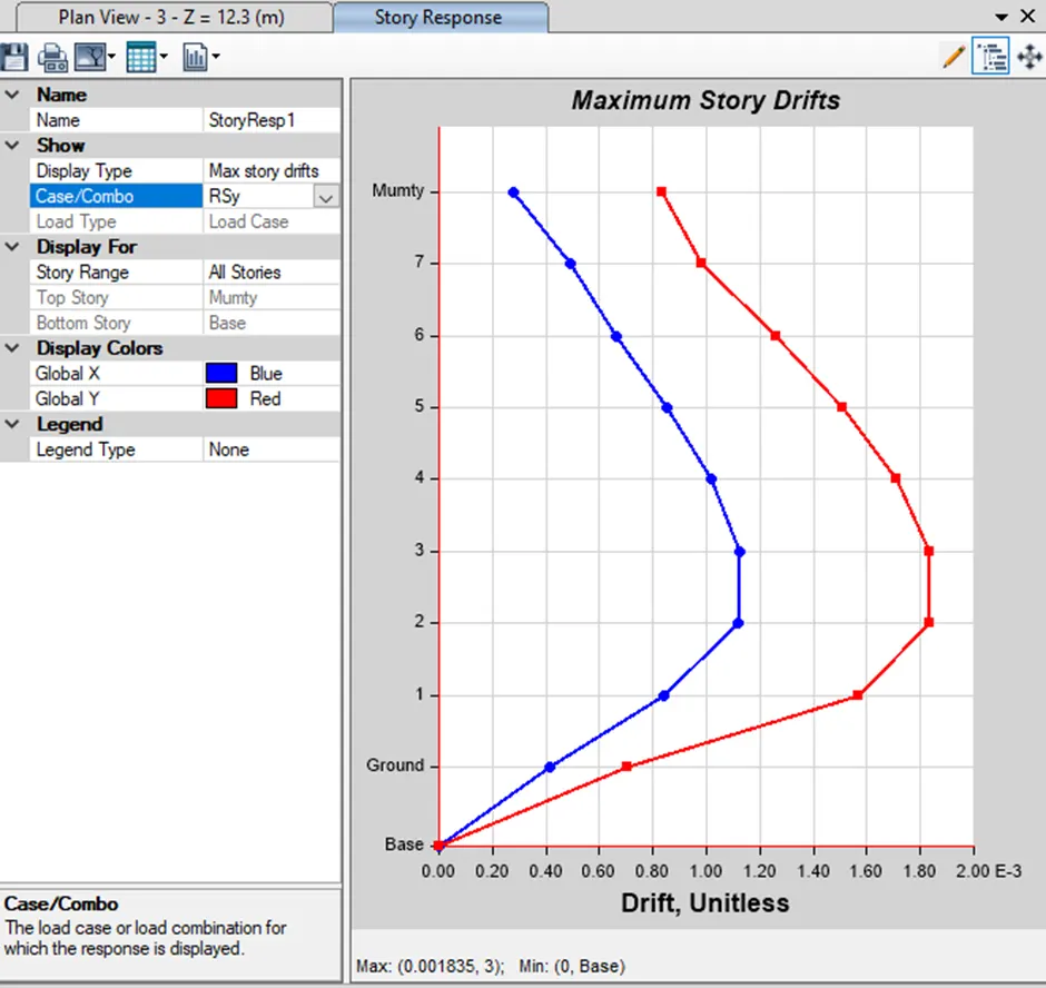
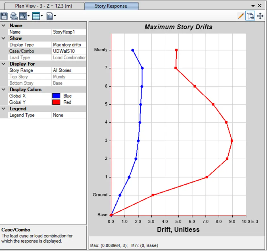
Step 26: Opening the reactions tab, then select the earthquake load towards X-direction(EQX) in the load case, then base reactions in that direction will come up as below:
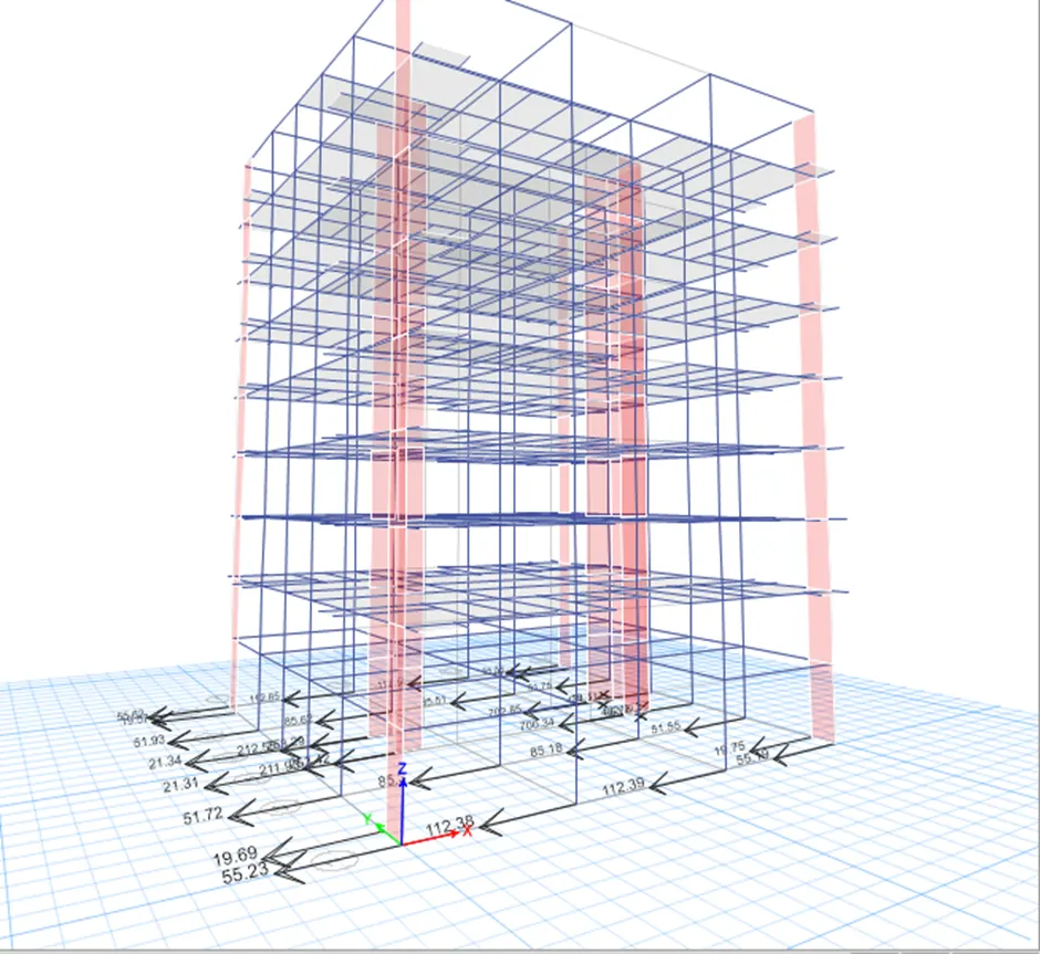
Step 27: When we divide the base shear taken up by the shear wall divided by the total base shear of building will get the % of the shear forces taken up by the shear wall.
And if that is less than 80%, then the more shear walls are needed to be add to the structure.
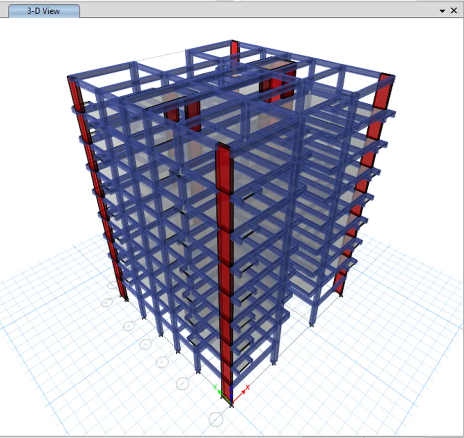
The final extruded view of the G+7 residential building modelled and analyzed successfully using the ETABS 2018 is as below:
Thannk you.