Structural Modelling using Etabs 2018
The architectural drawings for a G+7 residential building in zone 5 has been provided. The floor plan is the same for all 7 floor levels. Possible column positions have also been provided. Conceptualize a framing plan layout and then model the building in Etabs. The following architectural drawings have been provided:
- Typical floor plan – The location and thickness of the brick walls and the use of the
space (for estimating live load) can be obtained from this plan - A building section through the staircase and lift core is provided
- Parking layout in the ground floor – the column/shear wall arrangement must not
obstruct entry/exit of vehicles.
The following loadings are to be taken into account: - Brickwall made of AAC blocks
- Finishes – floor tiles of 75 mm thickness
- Live loads as per IS 875 part 2
- Water tank of 20 KL above the staircase at Mumty level
- Lift Machine room at mumty level above lift core
The structural model must comply with provisions of IS 1893 and IS 13920.
Run a modal response spectrum analysis and check analysis results of the etabs model for inter-storey drift requirements, vertical & planar irregularities, minimum shear wall requirements,maximum axial load ratio for column and shear walls, effective moment of inertia for beams
and columns etc.
Please note that the column positions shown in the architectural typical floor plan are only to provide an initial starting point for modelling. Participants will have to change its size, introduce shear walls, and add new vertical elements after running the analysis. You will have to run the analysis multiple times until a structural model is obtained that meets structural code requirements without compromising architectural functions. Also, there is no one ‘correct’ structural system for this challenge. There can be multiple possible solutions for this problem.
Aim: To model a structure using Etabs using the given architectural plan and to interpret the results.
Introduction: The process of creating a model in Etabs using the given architectural is a process which finalizes a project based on the results of the model. This process is like trial and error method as many specifications are there to be satissfied.Hence, a rough model with assumed sizes are made and from the results and based on the requiements changes are made until the model passes all the specification and many layout can be made for a single project also. In this model the two column sizes are used and one shear wall, beam and slab sizes are used.
Steps:
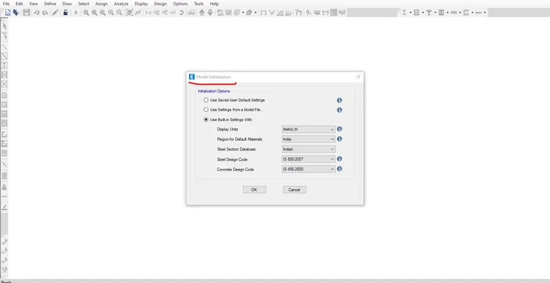
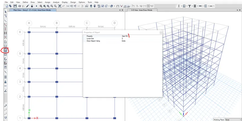
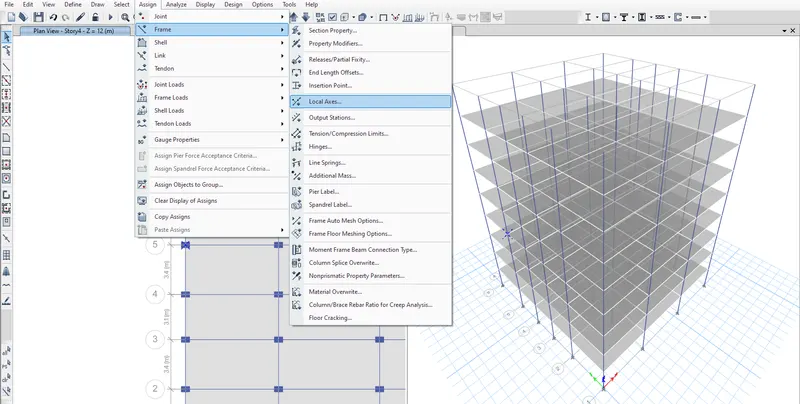
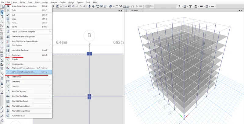
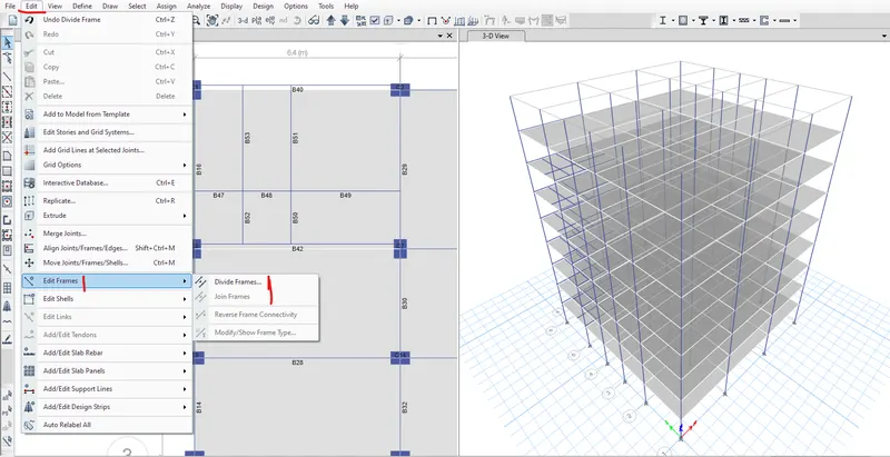
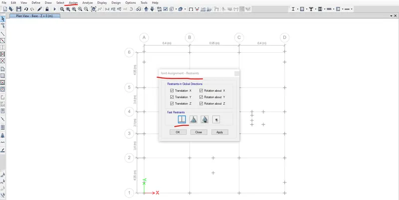
- Initially after opening the new file the standards and codes are set to Indian
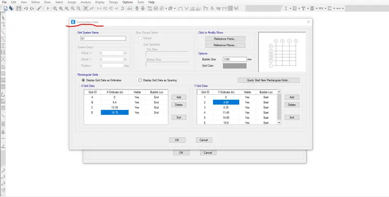
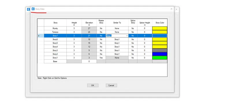
- Then the storey data and grid data are defined using the custom storey and grid data option and it is defined as per the architectural plan given.
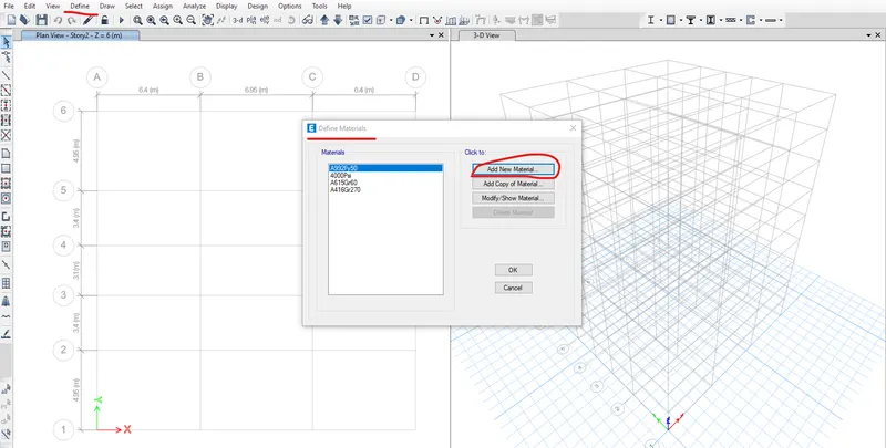
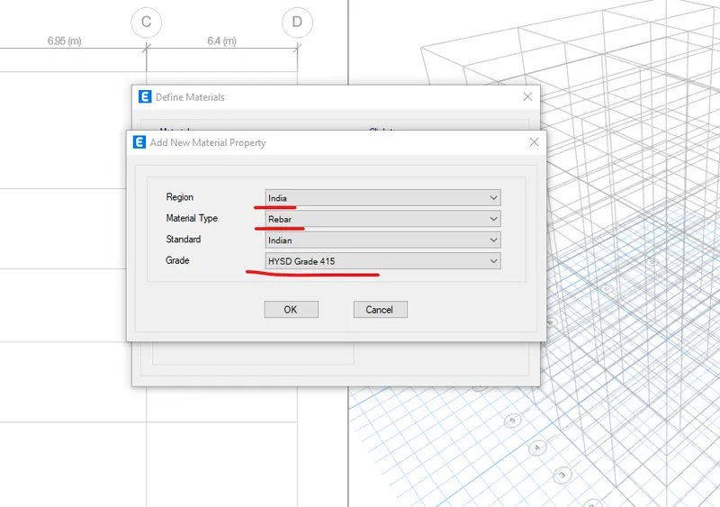
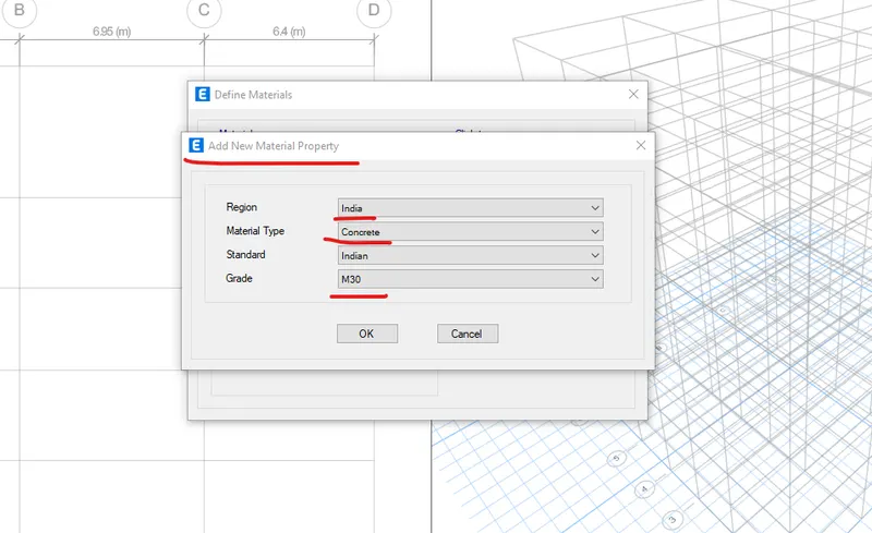
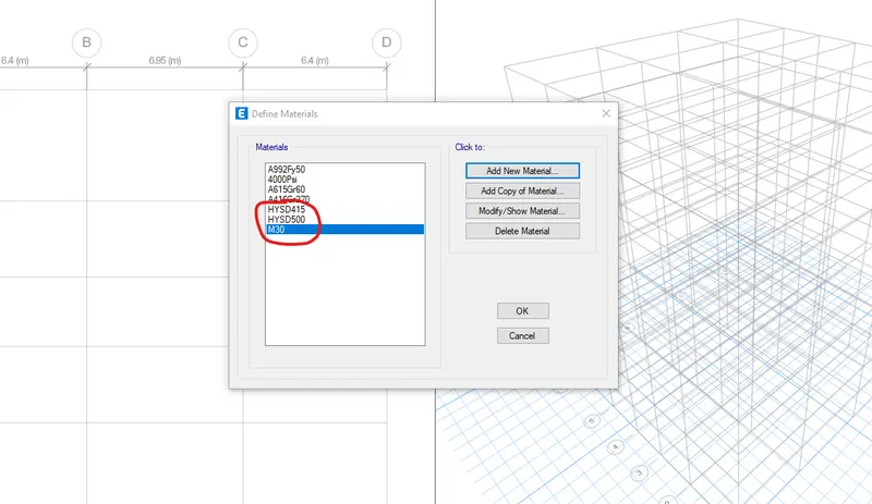
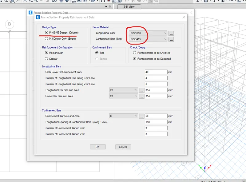
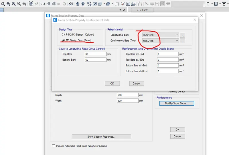
- Defining: The first step of any project is to define the properties. Initially the material properties are defined using the section properties>add new option from the define tab and the properties for steel HYSD 500 and 415 are defined.
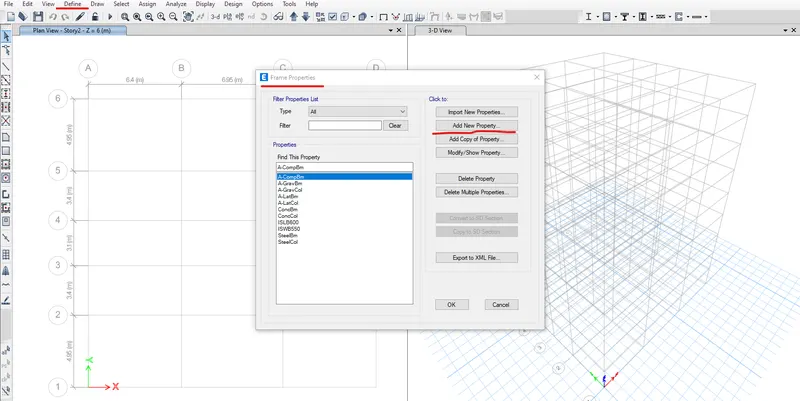
- Then the section properties are defined using the section properties>frame sections from the same define tab.
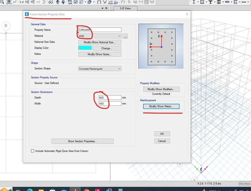
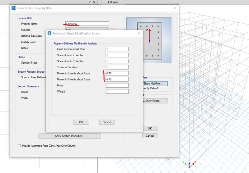
- The section properties added are beam and column. Column sizes of 400x600 and 300x300 are defined and the moment of inertia in both the axes are kept as 0.7 as per codal provisions using modfy/sjow modidiers option.
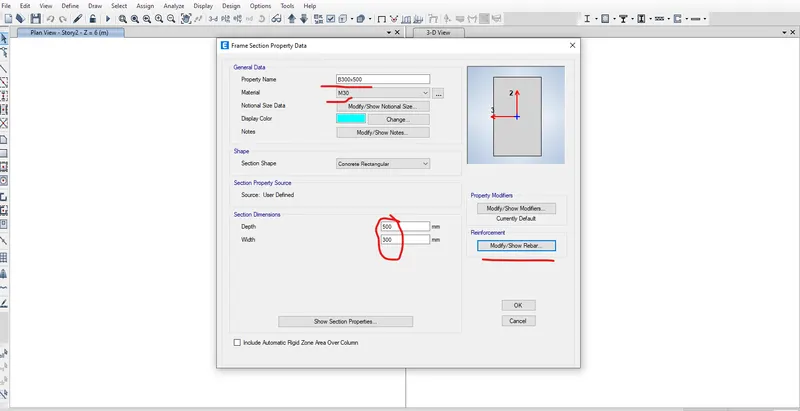
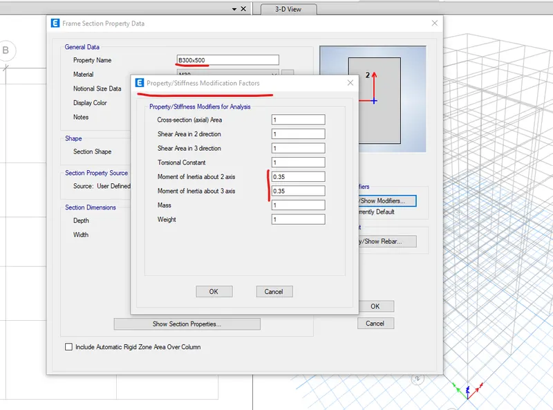
- The beam size is adopted as 300x500 and the moment of inertia in both the axes is kept as 0.35 as per codal provisions
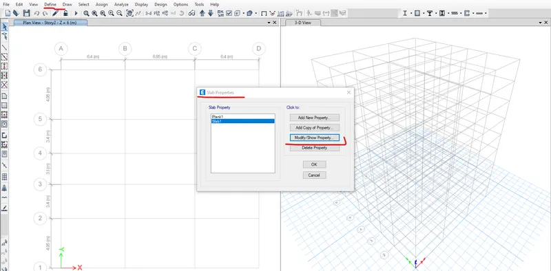
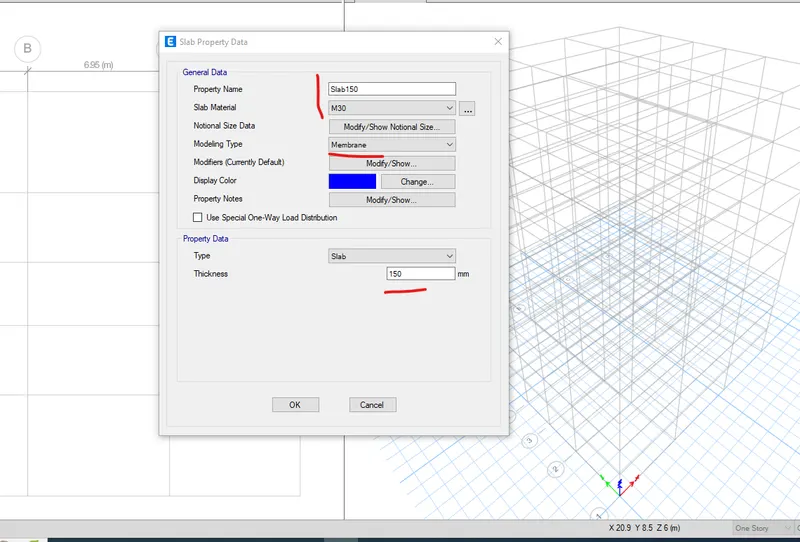
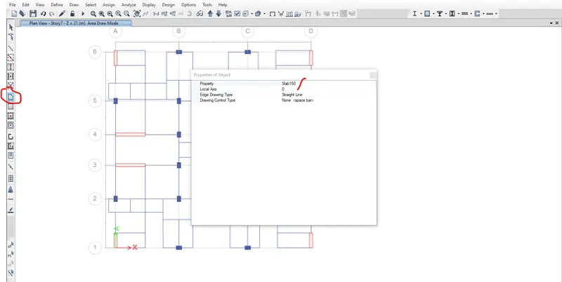
- Next, slab property is defined using section properties>slab sections>add new option and the thickness of the slab is adopted as 150mm
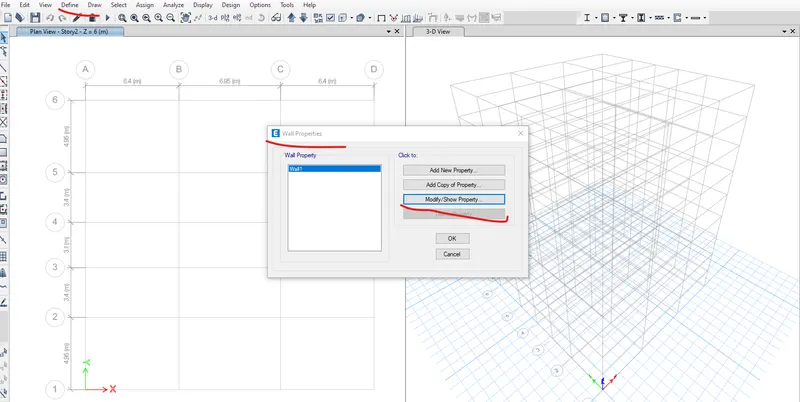
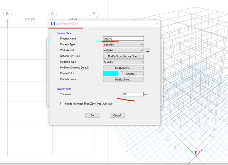
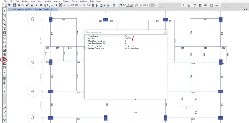
- Finally, wall property is defined using the section properties>wall sections>add new option and the thickness of the wall is assigned as 300mm.
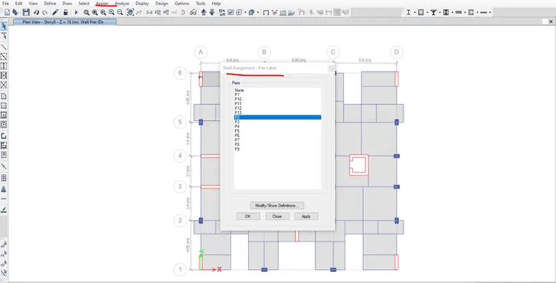
- Then pier labels are defined using the define>pier label>add new command and the labels are defined as per requirement.
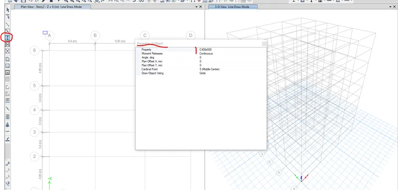
- Drawing: Using the quick draw column option from the left tool palette the columns are placed on all grid points
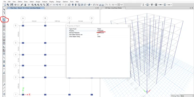
- Then using the quick draw beam option the beams are placed in the grid lines between the columns.
- For creating a typical layout as per given plan some of the editing options are used.
- The editing options are move and replicate. These are done by selecting the particular beam and from the edit the particular option replicate or move is used as per the requirement.
- In addition to these edit options divide and join frames option is also used to break or join a particular beam at the intersection as per requirement.
- Then using the draw rectangular floor option from the left tool pallette the slab is drawn from joint to joint intersection of the beam and draw floor option from the same tool pallette is also used for some irregular shaped slabs.
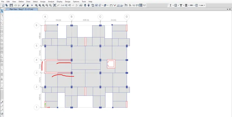
- Finally for adding shear walls quick draw walls option from the lef tool pallette is used and the walls are drawn carefully so as to satisfy the parking needs of the plan.
Model layout:
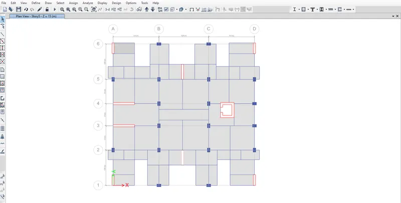
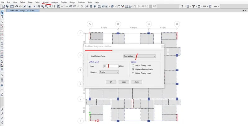
- Loads: After creating a layout the next step is to define and assign loads to the structure.
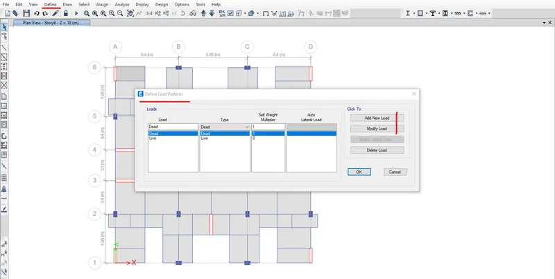
- Using define>load patterns the loads are added.
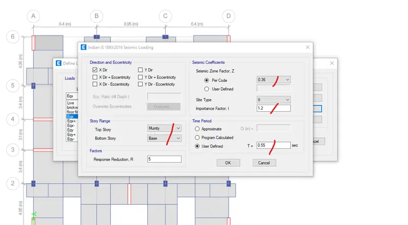
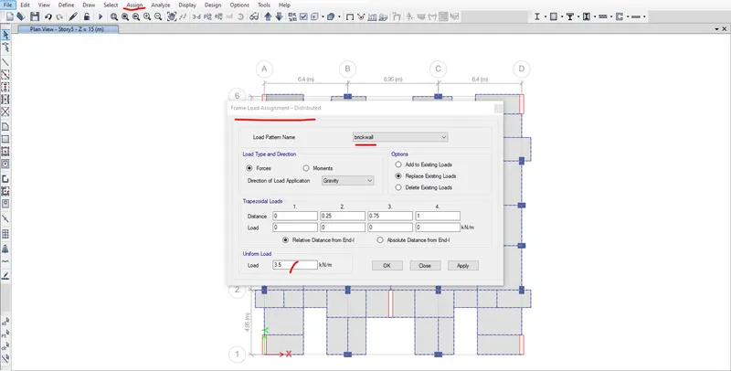
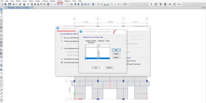
- Dead,live,brick wall and floor finishes loads are added and Earthquake loads in x and y direction are added and using modify lateral load option the code provisions like zone factor,importance factor,time period
- The time period is taken as 0.55s using the formula from code.
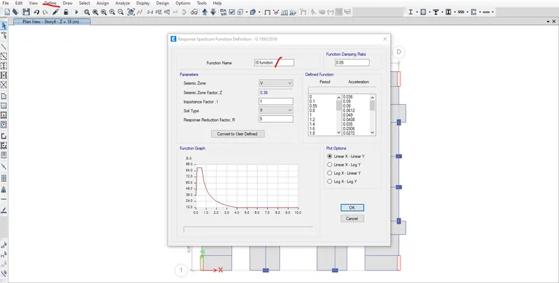
- Then using define>function>response spectrum>add new the response spectrum fucntion is defined as per IS1893 code.
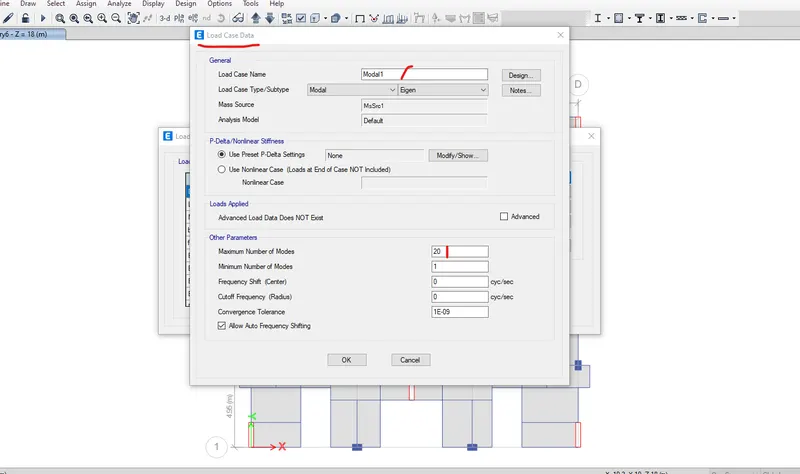
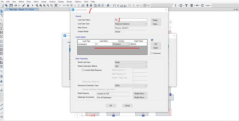
- Then using the load case >add new option from define tab Rsx and Rsy reponse spectrum cases are added in both the direction.
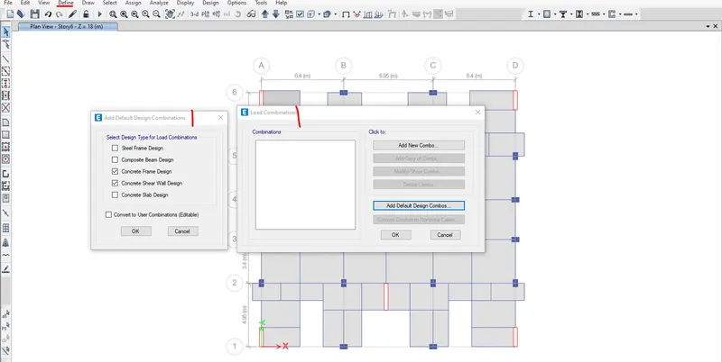
- Then using load combinations >add default design combo option the load combinations are defined
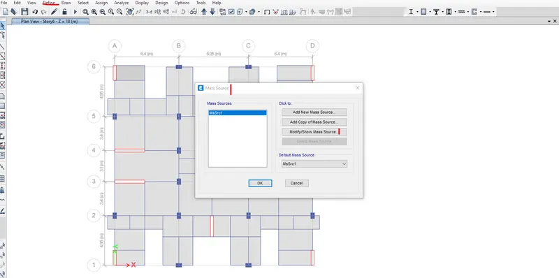
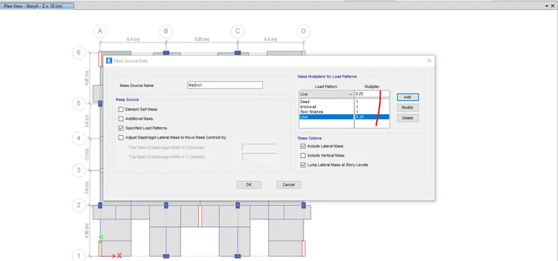
- Using define>mass source option the mass source for earthquake load is defined which is taken as 1DL+0.25LL.
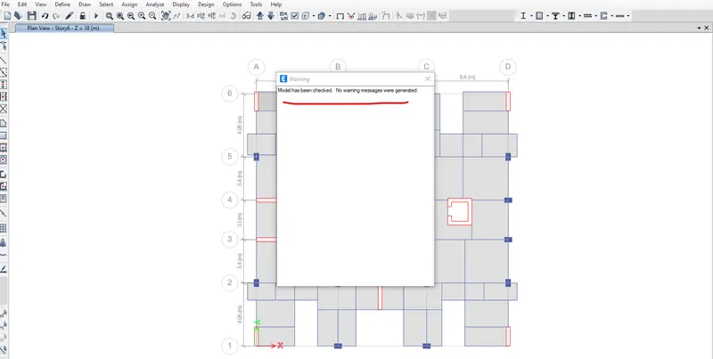
- Then analysis is done using the run option.
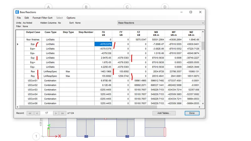
- From the results there is a huge difference between force values of linear earthquake loads and response spectrum loads
- Hence the scale factor is accordingly and the two loads are matched.
- The scale factor is modified by unlocking the model and using define>load case>modify option.
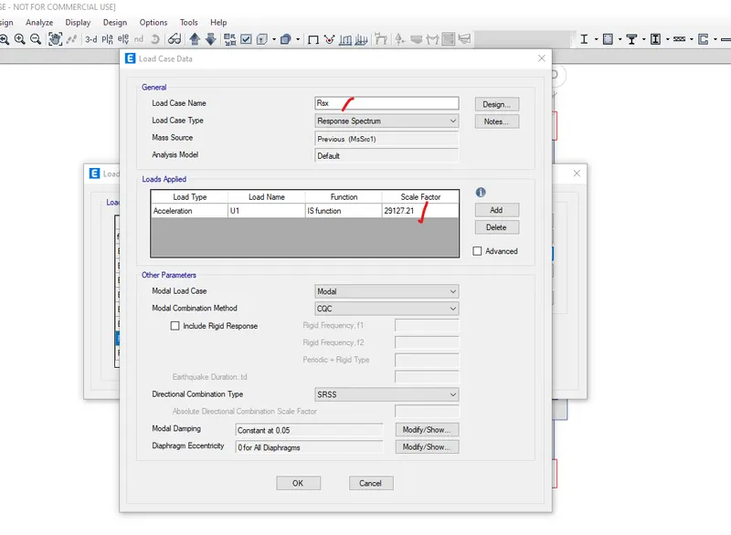
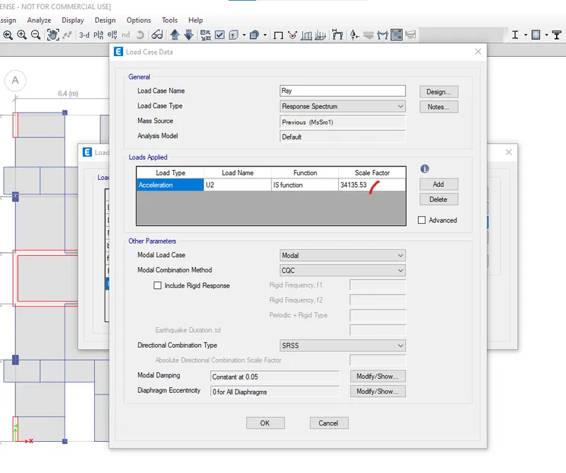
- After modifying the analysis is done again and the values are mathced.
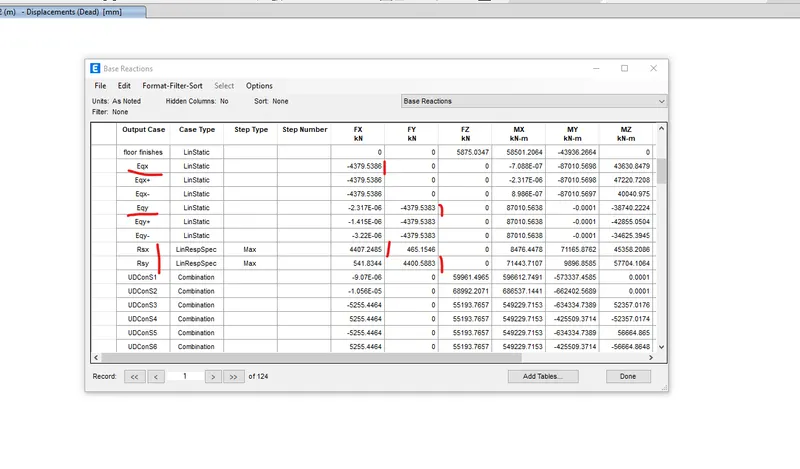
- From the results the story drfits are found to be higher than the code suggestion so more shear walls are added and the floor plan is modified.
Results:
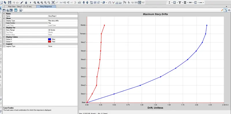
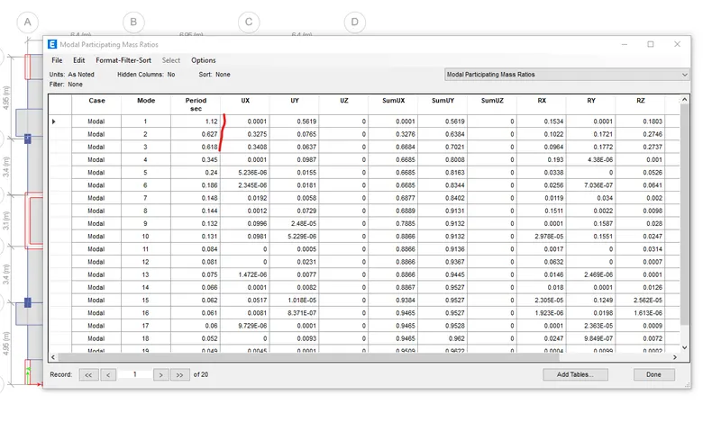
After making changes in the model the results were found to be satisfactory like the story drifts. The time period also satifies the codal provisions and the base shear bearing by shear walls and load ratio of columns are also calculated to be satifactory. Like mentioned model creation is a trial and error process thus, the created model is subjected to changed if required based on the results.