Drafting of various geometries using Chamfer, Fillet tool in AutoCad
Aim: To draw and draft various geometries using Chamfer, Fillet tool in AutoCad
Introduction: The drawings which are given are drawn using the various tools of drafting such as chamfer,fillet etc., These tools are mostly used to draw the drawings in simple way. These tools are precisely used to connect the drawings at the edges as per the required size and various gemoetries can be drafted using these tools.In AutoCad various tools usage pave the way for simple and easy way of creating drawings.
Drawings:
1:-

Steps:
- 1st step of the geometry after the initial setting is ab line which is drawn at 3.0 distance
- Then @2.12<135 deg a line is drawn which is bc line
- Then @2.83<90 deg a line is drawn which is cd line
- Then de line is drawn at @-2.0 distance and the gemoetry is closed.
- Then from a at 1.5 distance to the right and at 1 and 2.5 distance at top points are placed
- Two circles of 1.2 dia and 0.8 dia are drawn respectively at the points
- Then given gemoetry marked of its dimensions and finished.
2:-
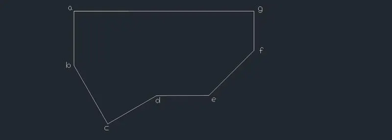
Steps:
- The initial step is to keep the settings in Architectural
- Then using the line tool @2'-5" distance ab line is drawn
- The bc line is drawn @3' distance is drawn similarly cd line @2'-6" distance at 45 deg is drawn
- Then ag line is drawn @8' distance
- The gf line is drawn @1'-9" distance in y direction
- Then @2'-10" <135 fe line is drawn
- Then d and e is connected using line and the geometry is closed.
- The dimensions are marked and the drawing is finished.
3:-
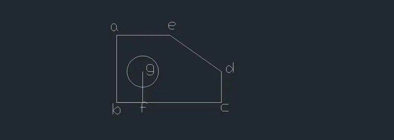
Steps:
- The initial step is to keep the settings in Engineering mode.
- The 1st step is to draw the ab line @3'-3.0" in downward y direction
- Then bc line is drawn @5'-0.1" in x direction
- The cd line is drawn @1'-6.0" in upwards y direction and de are connected using the line tool
- Then @1'-3.0" from b and a at a height of 1'-6.0" a point is placed
- Then at that a circle of 1'-6.0" dia is drawn
- The geometry is marked of its dimensions and finished.
4:-

Steps:
- The ab line is drawn @3.0 distance in right side x direction
- Then @0.5 in downward y direction bc line is drawn
- The cd line is drawn @2.5 in x direction
- The de line @2.5 in upward y direction is drawn
- The e to f lines are drawn @2.0 in -x direction and @3.0 +y direction
- The fg line is drawn @2.5 in -x direction
- Then gh line is drawn @1.5 in -y direction and ai line @3.0 distance and h,i are connected
- The dimensions are marked and finished
5:-
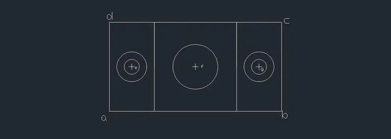
Steps:
- First a rectangle abcd of 11.5*6.0 size is drawn
- Then a point 'e' is placed @3.0 in x and @1.5 in y direction respectively
- Then @4.25 distance in x direction from 'e' point 'f' is placed
- The point 'g' is placed @4.25 distance from 'f' in x direction
- 2 circles of dia 1.0 and 2.0 are drawn respectively at points 'e' and 'g'
- A circle of dia 3.0 is drawn at point f
- Two lines are drawn perpendicular to points 'e' and 'g' @1.5 distance respectively
- The geometry is marked of its dimensions and finished.
6:-
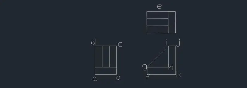
Steps:
- 1st a rectangle abcd of 1.5*2.0 size is drawn
- Then using the offset option @0.5 distance ab line is offsetted
- Then ad line is offsetted @0.5 distance respectively
- The e diagram is achieved by mirroring the abcd geometry
- The fk line is drawn @2.0 distance in +x direction and kj line in +y direction @1.5 distance
- The ji line in -x direction @0.5 distance and ih in -y direction @1.0 distance and the gh is closed
- Finally the g and i are connected using the line
- The geometry is marked of its dimesnions and finished.
7:-
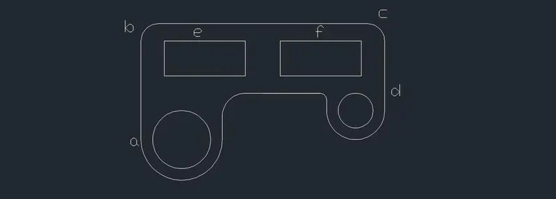
Steps:
- Initially ab line is drawn @100 distance in +y direction
- Further the bc line is drawn in +x direction @210 distance
- Then cd line is drawn in -y direction @ 75 distance
- Then a cirlce is created using the 'a' as the end point of 2P circle with 35 radius
- Another cirlce of 25 radius is drawn from 'd' as the end point
- Then the cirlces are trimmed to make it as a semi circle
- Then a circle of 50 dia is drawn at the centre of circle drawn near 'a'
- Another cirlce of 30 dia is drawn at the centre of the circle drawn near 'd'
- Then @60 distance from bc line a parallel line is drawn and connected with the circles
- Then two rectangles of 70*30 size are drawn from 20 distance from ab line and cd line respectively
- Then using the fillest option the edges are filleted at the required radius
- The dimensions are marked and finished.
8:-
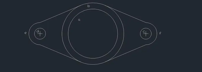
Steps:
- Initially 2 circles of 'a' and 'b' is drawn of 4.0 and 5.0 dia respectively
- Then from the centre of circle 2 points are placed at 4.275 distance on either sides of the circle
- Then circles 'c' and 'd' of 0.9 dia are drawn at the points
- Then circles 'e' and 'f' of 0.9 radius are drawn and the tangents are connected with the 'b' circle and the extra portion is trimmed to get the geometry
- The dimensions are marked and finished.
9:-

Steps:
- The first step is to place two points 'a' and 'b' at 32'-6" distance
- Then 2 circles 'd' and 'c' are drawn at the points with 8' and 9' radii respectively
- Then a circle of radius 41'-8" is drawn using the tan tan radius option of circle by using the 'd' and 'c' tangents
- Then a circle of radius 20'-10" is drawn using the tan tan radius option of circle by using the 'd' and 'c' tangents
- Then the portions are trimmed to get the desired geometry.
10:-

Steps:
- First a square is created using the polygon option of 4 sides
- The created square is offseted @0.5 distance
- Then the resultant squares are mirrored to 45 deg and the unwanted portions are trimmed to get the required geometry.
11:-
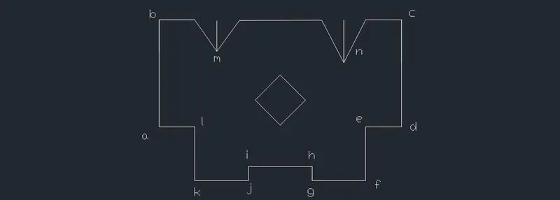
Steps:
- The ab line is drawn in +y direction @6'-9" distance
- The bc line is drawn in +x direction @20'-4" distance
- The cd line in -y direction @9' distance
- The de line in -x direction @3' distance
- The ef line in -y direction @4'-6" distance
- The fg line in -x direction @4'-6" distance
- The gh line in +y direction @1'-2" distance
- The al line in +x direction @3' distance
- The lk line in -y direction @4'-6" distance
- The kj line in +x direction @4'-6" distance
- The ji line in +y direction @1'-2" distance an the 'i' and 'h' are connected usin the line
- Then from b @3' distance a line is drawn at 45 deg @2'-8" distance which is m and another line is drawn from m at 45 deg which intersects the bc line
- Then from c @3' distance a line is drawn at 30 deg @3'-7" distance which is n and another line is drawn from n at 30 deg which intersects the bc line and the unwanted portions are trimmed
- The geometry is marked of its dimensions and finished.
Result: The given geometries are created precisley using the fillet modification tools. The snap mode and polar tracking options are also used to interpret the points at certain intersections and to place the points at a certain distance with repsect to the drawings.The usage of the editing options such as trim are also used to delete the lines which are unwanted in the geometry.The usage of the modification and editing tools are used to create the drawings in easy and simple manner.