Creating a Floor plan, Footing detail and Isometric view using AutoCad
Aim: To create a Floor plan, Footing detail and Isometric view drawings using AutoCad software.
Introduction: The given drawings such as cross sections of footings with bearing wall, line diagram of a two rooms,isometric view drawings of stairs and a wall are drawn in the software using the tools such as Rectangle,Line and also modification tools such as offset are used.The modification tools such as chamfer,offset,move,copy are used for the purpose of making the drawings drawn easily and reduce the time period used to drawn the drawing.For eg the modification tool offset provides copy of the objects at the required distance hence reducing the time for redrawing the same objects again.
Procedure:
C1:

- The drawing is started by drawing a rectangle (abcd) of 0.9*0.25
- Then using the line tool the other sections such as d,e,f,g,h,i,l,m are drawn as per the given dimensions and m line is closed in dc line of the rectangle
- The h,i line is offseted at a distance of 0.05 which is n,o line
- Then at a distance of 1.6 n,q line is drawn and at a distance of 0.3 q,p line is drawn and the line is closed which is p,o line.
- Then wall cross section is drawn at left of the the drawing from g at 1.15 distance with cross section of steps at 0.15 tread and 0.30 rise.
- The other side of the drawing is given with the wall at the same distance of 1.15 and at height of 0.6
- The drawing is finished and the dimensions are marked.
C 2:
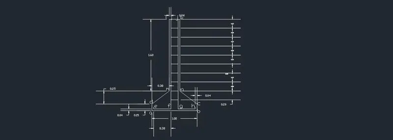
Steps:
- The diagram is started by drawing a line from a to b at 1.0 distance and another line b,c at 0.15 distance
- Similar like b,c line a,d is drawn
- Steel detailing is drawn which starts at e,f and g,h line at 0.38 distance and at a distance of 0.04 from on either sides of a,d line and b,c line
- Then using offset option at a distance of 0.2 steel lines are placed which ends at i and j
- Then using line command at a distance of 0.04 at either sides of i,j line is drawn which is l,k
- Using the line command l,m and k,n line is drawn at 1.6 distance.
- Then m is connected with d.Similarly, n is connected with c.
- The given drawing is finished and the dimensions are provided.
C 3:
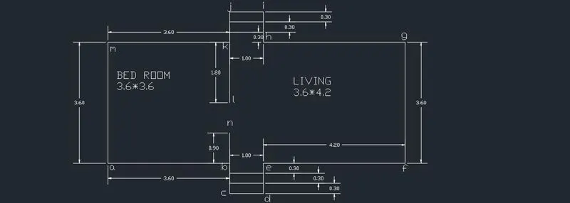
Steps:
- The given line drawing of two rooms is started at the point 'a' using line tool at a distance 3.60 ab line is drawn
- Similarly bc line is drawn at 0.9 distance and cd line at 1.0 distance and de line is joined
- In the bcde lines steps is given at the diagram at a distance of 0.3 which is done using the offset option.
- Similarly the other room of distance 4.2*3.6 is drawn using line tool.
- The other side of the drawing also consists of steps which is hijk is drawn using the offset option at same 0.3 distance.
- Lastly the line b,n and k,l is drawn at 0.9 and 1.8 distance respectively.
- The given diagram is finished and the dimensions are marked.
C 4:

Steps:
- The diagram is started using rectangle tool option abcd is drawn at 0.9*0.6 measurements.
- Then using the line tool d,e line is drawn at 0.15 distance.
- Consequently e,f f,g g,h h,i i,j j,k k,l l,m m,n n,o is drawn at the given and required distance.
- The o line is closed at dc line of the rectangle.
- The j,p line is drawn at 1.0 distance and p,q line at 0.3 distance and q is closed at j,k line.
- The diagram is finished and the dimensions are marked.
C 5:
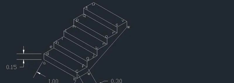
Steps:
- The initial step for drawing this stairs object is to set it in the isometric view and checking out from snap mode.
- The next step is to keep the ortho mode on for this drawing to be in straight line.
- The a,b is drawn using the line tool at 1.0 distance and the isometric toggle is changed direction for b,c line which is drawn at 0.15 height similar to a,d line and c,d are connected.
- The d,e line is drawn at 0.3 distance by changing the isometric toggle right option similarly c,f line is drawn and e,f is connected. Hence, a single step is drawn by changing the isometric toggle to different angles.
- The same procedure is followed for the other 4 steps .
- The b,w line is drawn at 0.3 distance in right direction and v,w line at 0.15 distance in downwards and both w's are connected which completes the steps.
- Hence the isometric view of steps are created and the dimensions are marked using the aligned option as the diagram is in isometric view.
C 6:
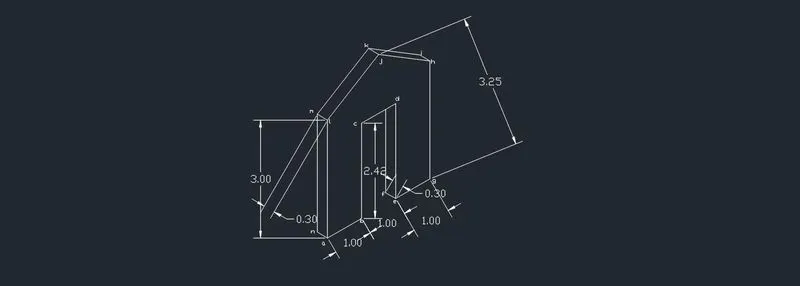
Steps:
- The initial step is to keep the settings in isometric view followed by keeping ortho mode on.
- The a,b line is drawn at 1.0 distance in right direction and b,c at 2.42 in upwards and c,d line in downwards with 2.42 distance.
- The e,f line is drawn with 0.3 distance in left direction and the 'f' is joined in c,d line which represnts the thickness of the wall.
- Then e,g line at 1.0 distance in right direction and g,h line at 3.0 distance in upwards.
- Then a,n line at 0.3 distance in left direction and n,m line at 3.0 distance in upwards and m,l line at 0.3 distance and 'l' is connected with a.
- To connect the top, line of 1.5 distance is drawn from 'a' towards right and from there at 3.5 distance, line is drawn in upwards which is 'j' point.
- This line is for connecting purpose and it is erased after connecting 'j' with l and h on either sides.
- From j at 0.3 distance j,k line is drawn in left direction similarly h,i is drawn in left direction with same distance.
- Then 'k' is connected with n and i on either sides which represents the thickness of the wall at top.
- The measurents are marked and the drawing is finished.
Results: The given floor plan, C.S of footings and stairs,wall in isometric view is drawn and the tools such as rectangle are used. The mdification tools such as move,copy,offset and modes such as orthomode are learnt and used.