Structural Modelling using Etabs 2018
Aim: to model and analyze the G+7 stoey building using Etabs with application of proper load cases and load combinations for the given typical floor plan drawing.
Procedure:
- Open the ETABS software.
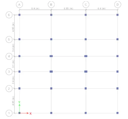
- Set the grid and storey details using editing options.Provide 4 grids at X direction and grid at Y direction with proper spacing.
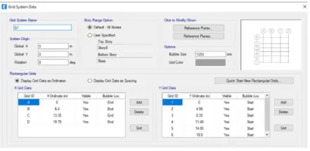
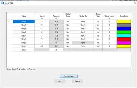
- Now define each storey and story height.
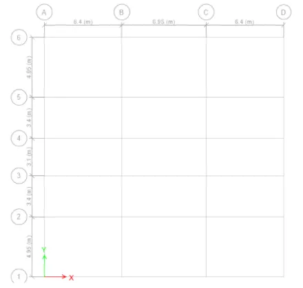
- Click define tab and select the materials.Choose the material type asconcrete for M25.
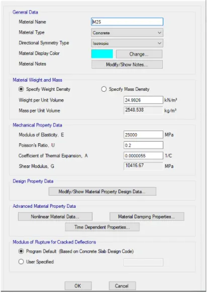
- Similarly for rebar material.click define slect add new material option and choose the type as Rebar.
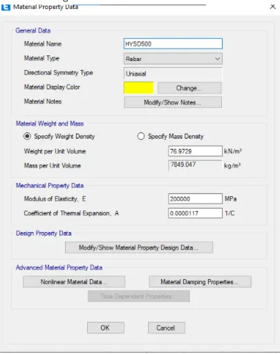
- Click define tab and select frame section property.
- Provide the beam dimension as 350X550.Then modify the rebar details.
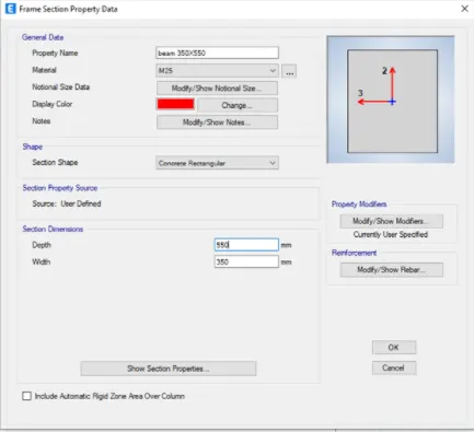
- Select define tab and select frame section property.
- Provide the column dimensions as 400X600.Then modify the rebar details.
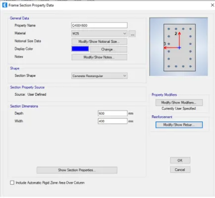
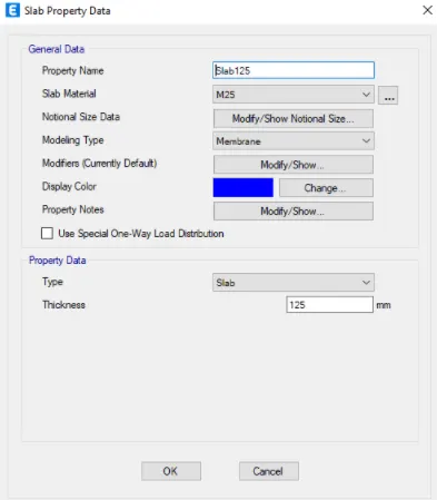
- Click define,select section propertes and click on slab sections.
- Provide the thickness of the frame as 150mm.
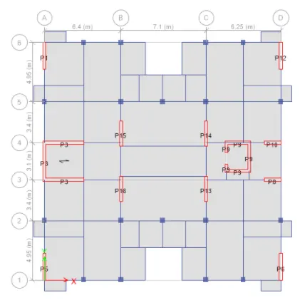
- By using the quick draw column/beam option place the columns in the floor plan at each grid intersection.
- Select all storey option.
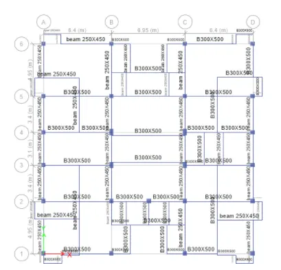
- Similarly draw the beam per the floor plan.
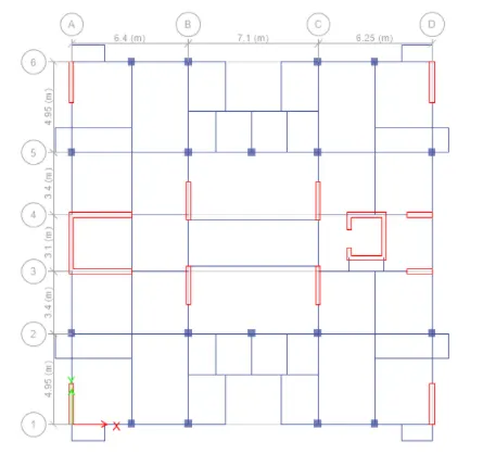
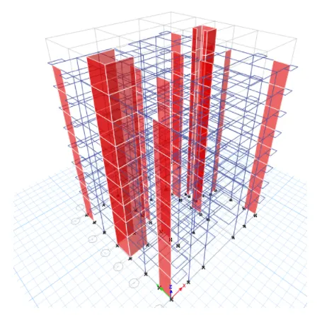
- Draw the shear walls in required places.
- Click on the plan and select base and select one story.
- Select all the column base.
- Click on assign,select joint and select the joint as fixed.
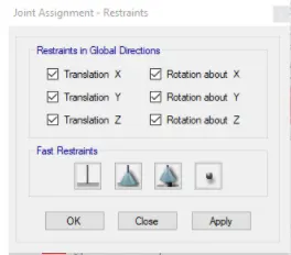
- By using the quick draw flor/draw rectangular floor plan option place the floors.
- Select all storey option.
- Click on load patterns and define dead,brick wall and live load.
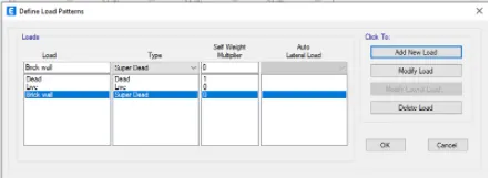
- Apply the brick wall load in all the beam component.
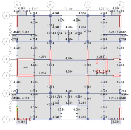
- Apply live load as per IS 875.
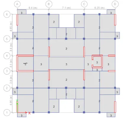
- Live load= 2KN/sq.m(As per table 1 from IS 875 part 2)
- Live load= 3KN/sq.m for balconies,lift area and walkway(as per table 1 from IS 875 Part 2)
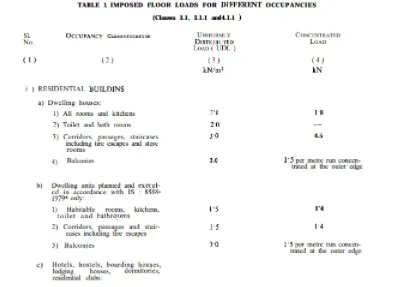
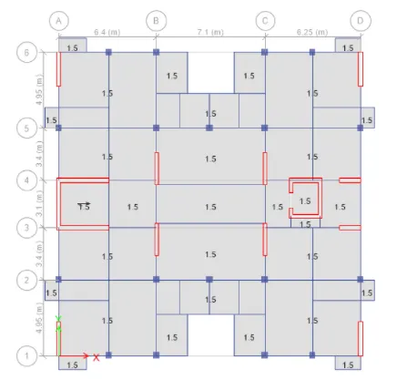
- All the roof we take 50% of live load.
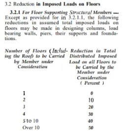
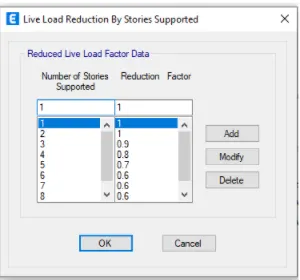
- Similarly the reduction factor has benn taken from clause 3.2.1 in IS 875 part 2.
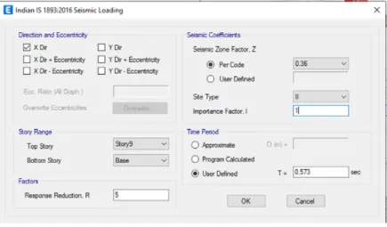
- Click on the load patterns and define the seismic loads.
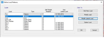
- Calculate the time period T value from IS 13920 clause no 7.6.2
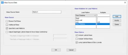
- Define the mass source.
- Go to define and click on the pier labels.
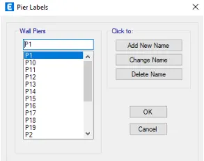
- Select the shear walls one by one and assign the pier labels.
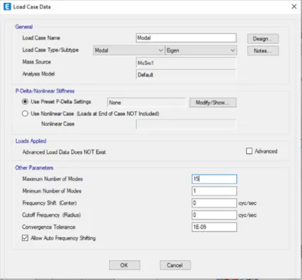
- Click on the load cases and define the number of modes.
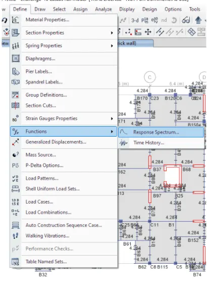
- Click on define,select function and select on response spectrum.
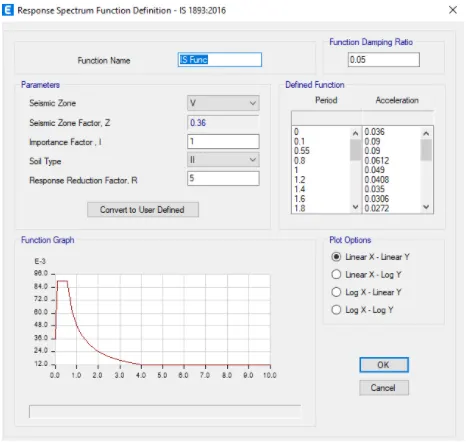
- Define the response spectrum in both X and Y direction.
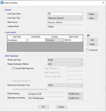
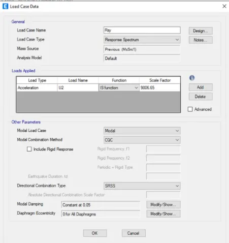
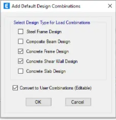
- Select load combinations and click on the default design combinations.
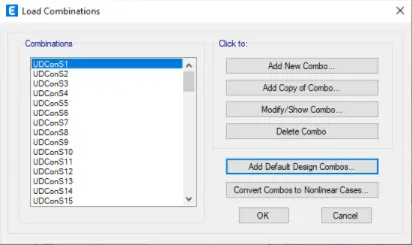
- Select analyze and click on check the model.After the model checking click on run the analysis.
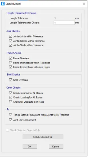
- Select display and click on show table.
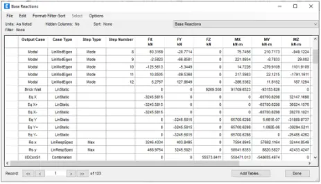
- Unlock the model.By using the base reactions adjust the scale factor in response spectrum.
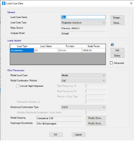
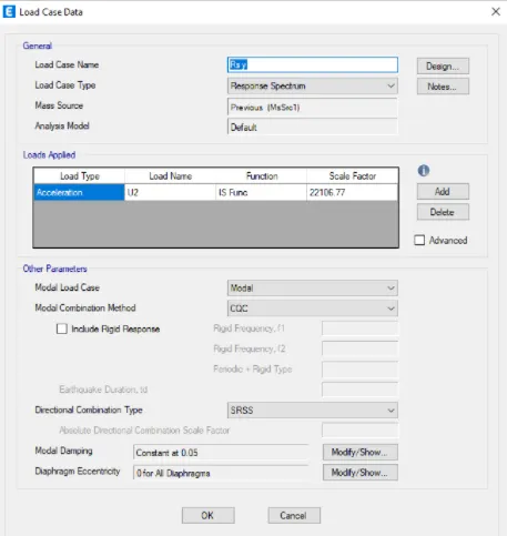
- After that run the analysis and see the inter-storey drifts.The drifts should be within 4 %
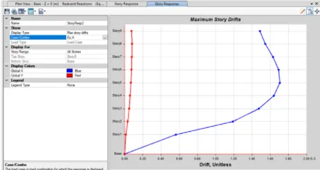
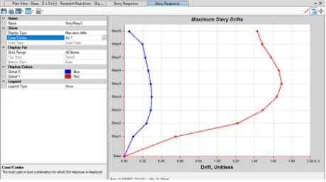
Base shear is greater than 80%
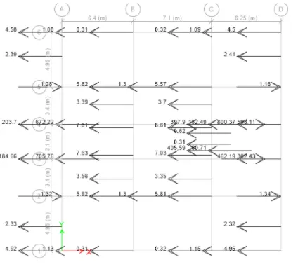
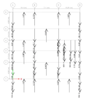
Conclusion: the analysis has been done successfully.