Structural Modelling using Etabs 2018
Aim:
The objective of the challenge is to create the best structural feasible plan for the given architectural plan. And to model the framing plan in ETabs for G+7 building.
Forming of schematic framing plan :
Step:1
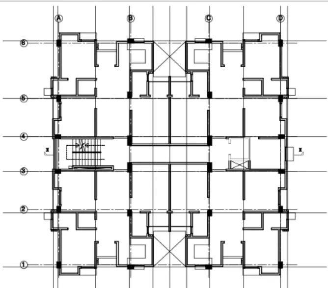
For the provided architecture drawing, the alignment of the walls and columns are set up using reference lines traced through the walls and columns.
Step:2
With the use of the reference grid lines, we can clearly see where shear walls should be placed in order to eliminate the architect's suggested preliminary column positions.
Shear walls are used in place of columns in the circled area to support lateral loads.

Step:3
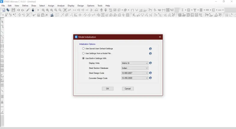
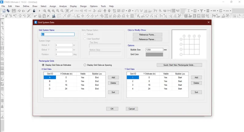
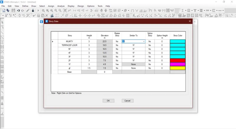
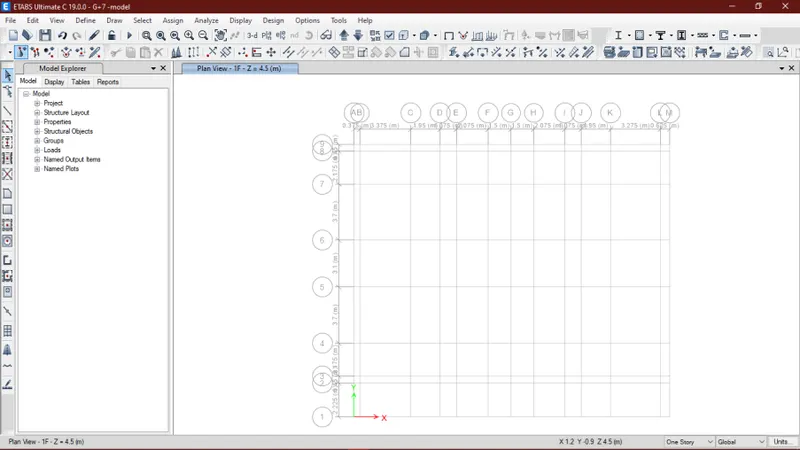
Create a new model and create the foundation grid line using the grid and storey editor. and choosing the IS codes for the model's analysis.
Step:5
Concrete and reinforcement material properties were assigned using the define option in accordance with the suggestions of the IS Code.
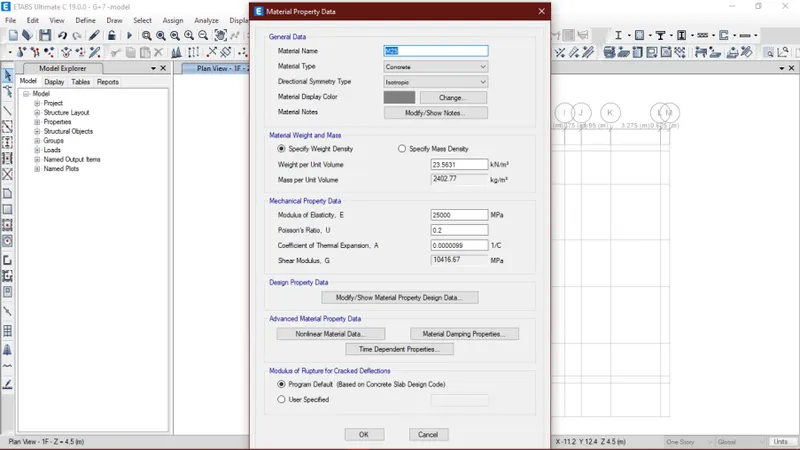
The characteristics of concrete are based on M25 grade concrete.
Step:6
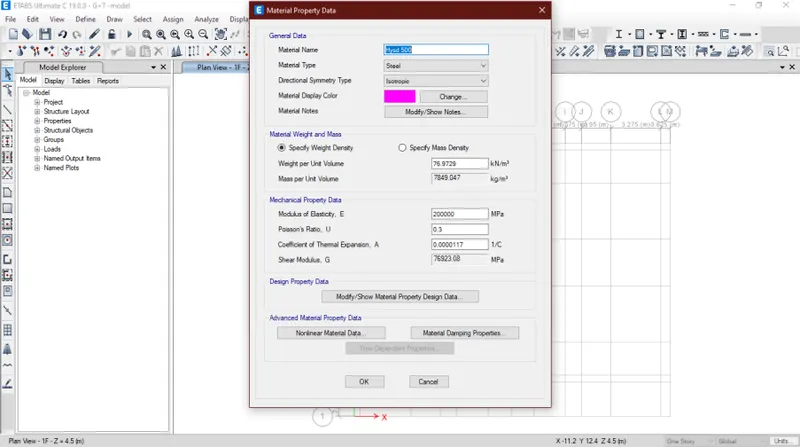
In terms of reinforcement material For shear design, fe415 steel was assigned, and fe500 steel was designated for flexural design.
Step:7
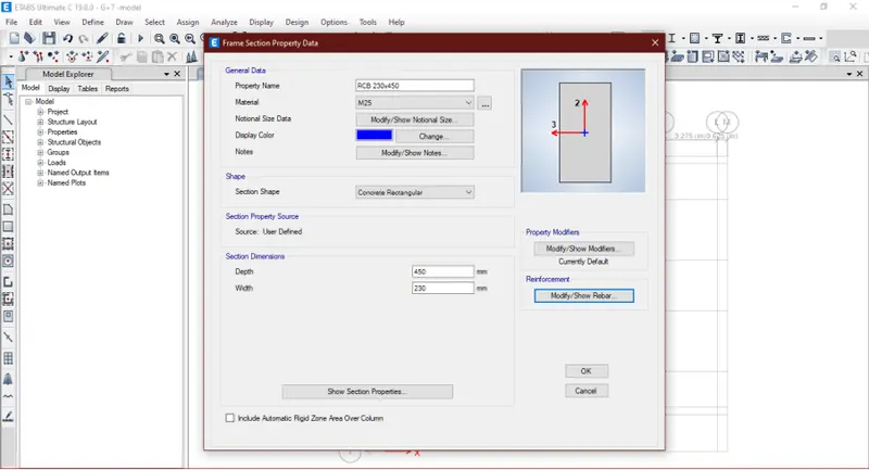
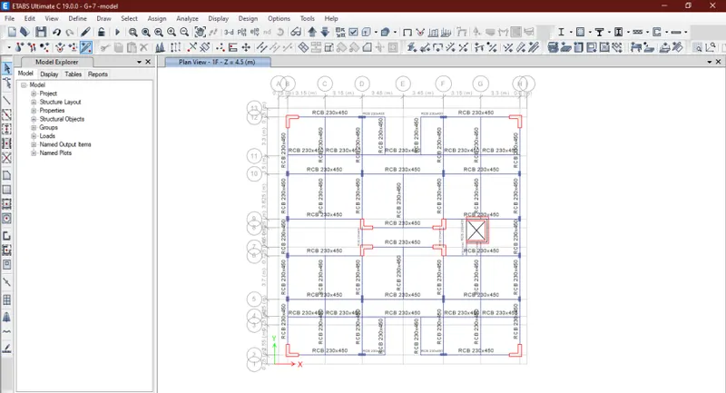
The 230x450mm frame section is assigned using the define section settings.
Step:8
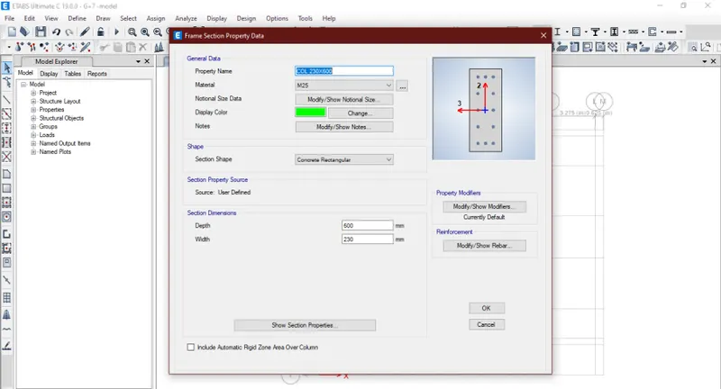
The frame section for the column is generated using the section attributes.
For the internal and exterior columns, there are two different column sizes established.
Step:9
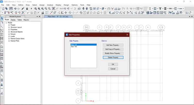
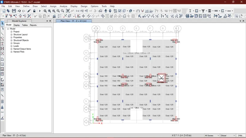
Using the section characteristics, specify slab sections that are 150mm thick where stairs are located and 125mm thick where slabs are located.
Step:10
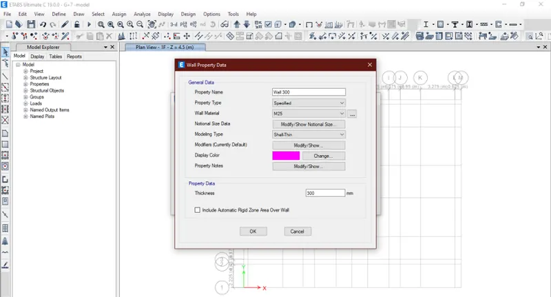
Utilizing the section characteristics, 300mm-wide wall sections are defined to withstand lateral and seismic loads.
Step:11
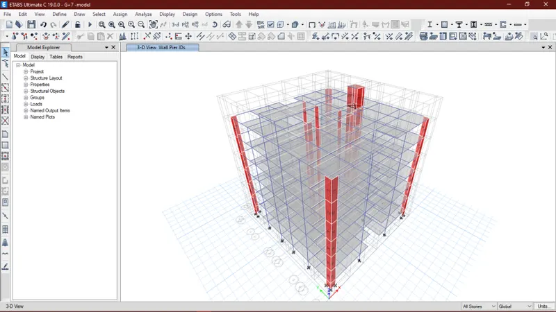
Using the define option the pier label is created for individual walls in the structural framing plan.
Step:12
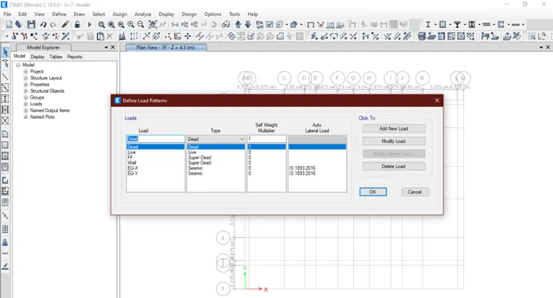
In define option,The load patterns -required load patterns are now included.
Dead load (self-weight), floor finish, and wall load are added with reference to IS 875 part 2. added live load of 2kN/sq.m.
In accordance with IS 1893-2016, the EQX and EQY codal references were also developed.
Step:13
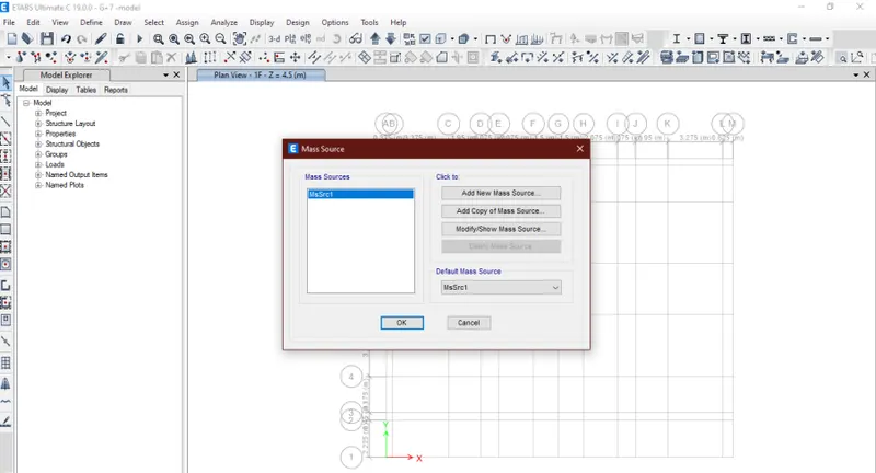
The building's mass source is altered using the define option.
According to the IS code 1893-2016, the live load factor is 0.25 for Y direction and dead load equals factor 1.
Step:14:
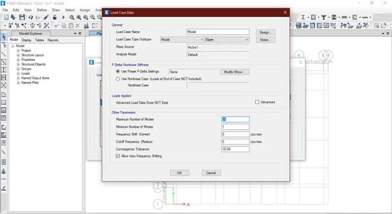
By using the define option , the modal case of the seismic modal case is assigned as maximum 20.
Step-15:
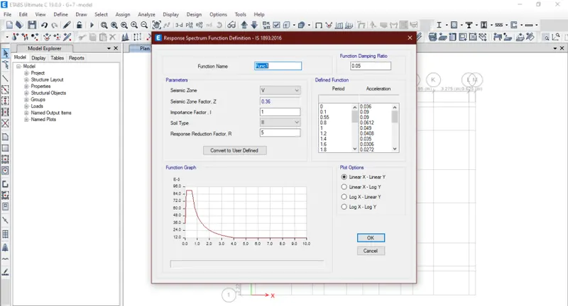
Add new functions by changing the function > response spectrum option using the define option.
The Zone -5 base is developed for this model's reaction spectrum for mathematical function.
Step-16:
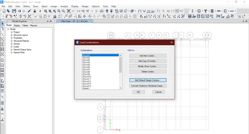
The default load combinations are created for the frame and concrete wall designs using the define option for load combinations.
Step:17
At the GL junction points, columns are generated using the rapid draw choices, and columns or walls are also placed at the necessary location using the Grid reference.
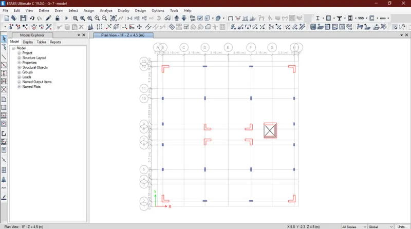
Floor Area: 20 x 20 = 400 square metres
Assumed total length of RC wall is 19.9 metres, or 5.97 square metres of shear wall.
Ratio =5.97/400=1.49%
Step:18
Using the quick draw beams, all the beams are drawn.
Step:19
Using the quick draw slab areas , all the slabs are assigned as 125mm and for stair location 150mm slab provided.
Step:20
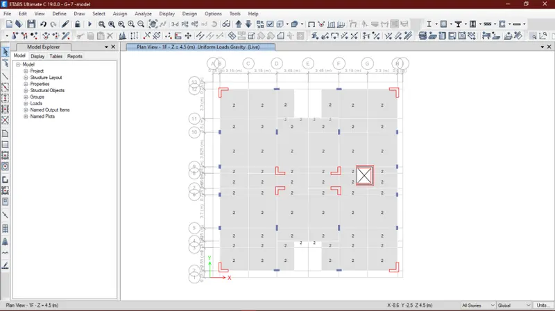
Live load of 2kN/sq.m is assigned to slab ad per IS 875-Part-2 Codal recommendation.
Step:21
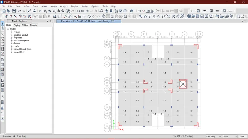
Floor finish =75mm =0.075*20=1.5kN/sq.m
Where concrete mortar density is 20 kN/Cu.m
Step:22
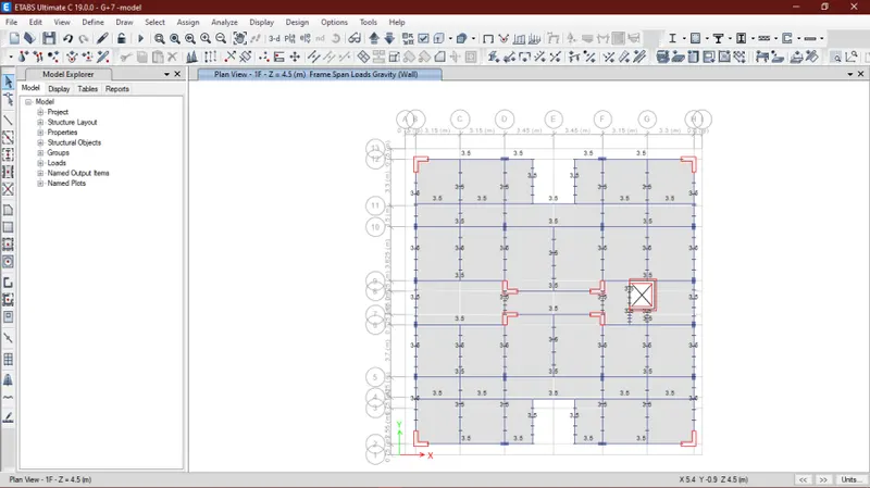
By considering AAC block density of 6.5 kN/Cu.m.
Line load of wall load ,=6.5*.2*2.55m height of building
=3.5kN/m
Step 23:
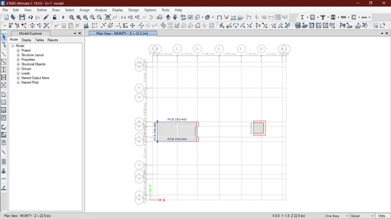
Above terrace floor for head room location single slabs are modelled and water tank load is considered.
Step:24
For foundation @ base level, all the joints are provided as fixed support.
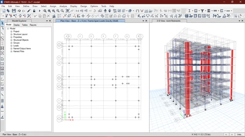
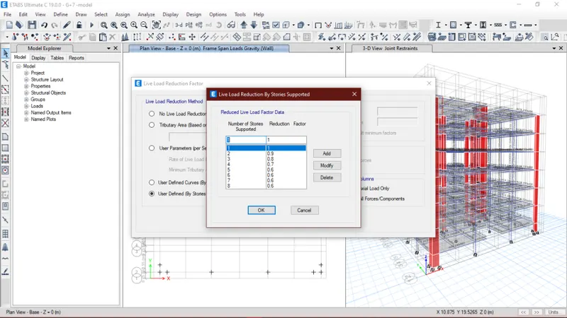
Step:25
Live load reduction factor is assigned as per the code reference of IS 875 part-2.
Step:26
Utilize the check analysis tool bar to check the model for errors.
The Run Analyze tool bar is then used to conduct the analysis.
Additionally, consider the frame and slab designs.
Verify the overall system's behaviour for any modelling flaws.
Step:27
Using the display tool bar after analysis ,
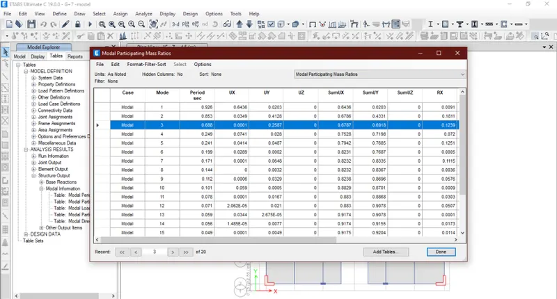
Display > analysis result > structure output >modal information >modal mass partipation ratio
Check the first two fundamental modal mass greater than the torsional mode.
Step:28
Using the display tool bar after analysis ,
Display > analysis result > structure output >Base reaction
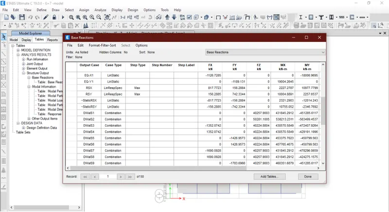
By using the seismic forces the from EQ-X and EQ-Y with respect to RSX & RSY the scale factor for spectrum response is calculated.
Step:29
Calculating the form factor for the EQX/RSX and modifying the defined shape factor for the Response spectrum load scenario for RSX & RSY utilising the shape factor that was finally arrived at
Step 30:
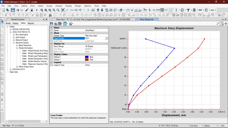
For the RSY option, display the toolbar > storey response plot > interstorey drift.
to observe the inter-story drift, which, according to the code provision 1893-2016, is less than 0.004.
Step:31
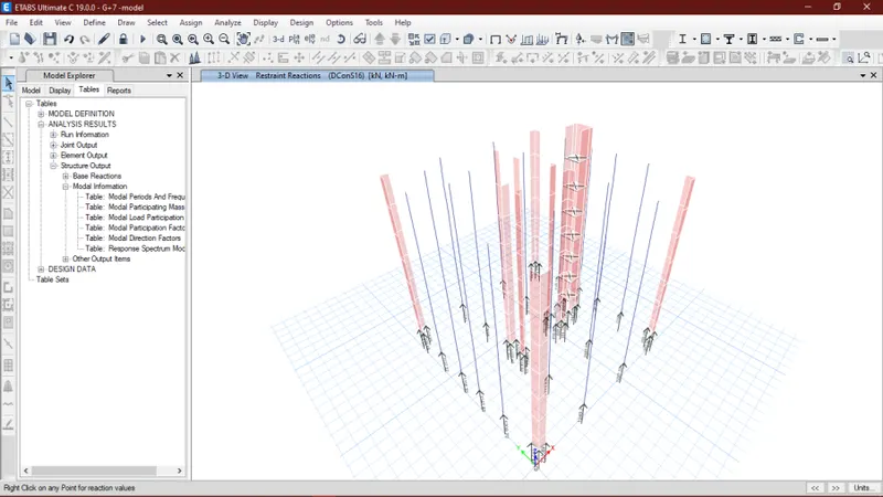
Using the display tool bar, in drop down force /stress diagram >frames,
For all load combinations, the base force of the columns is examined for its compressive limit.
Step:32
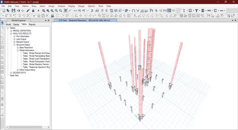
Using the display tool bar, in drop down force /stress diagram >pier forces,
All load combinations' compressive limits are verified using the base force of the shear walls/pears.
Verify the cap, which is (0.28 fck).
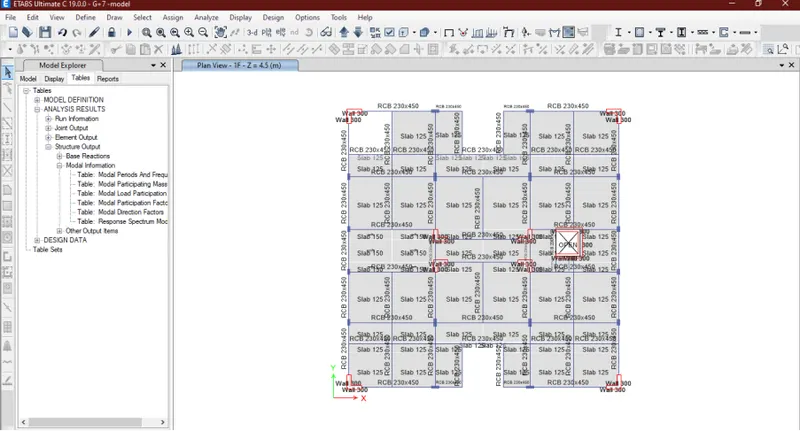
Step 33:
After all arrangement and modifications the final structural layout is shown below,
Attachment : The Final etabs model is attached with the project.