Structural Modelling using Etabs 2018
Aim :-
The architectural drawings for a G+7 residential building in zone 5 has been provided. The floor plan is the same for all 7 floor levels. Possible column positions have also been provided. Conceptualize a framing plan layout and then model the building in Etabs. The following architectural drawings have been provided:
- Typical floor plan – The location and thickness of the brick walls and the use of the
space (for estimating live load) can be obtained from this plan - A building section through the staircase and lift core is provided
- Parking layout in the ground floor – the column/shear wall arrangement must not
obstruct entry/exit of vehicles.
The following loadings are to be taken into account: - Brickwall made of AAC blocks
- Finishes – floor tiles of 75 mm thickness
- Live loads as per IS 875 part 2
- Water tank of 20 KL above the staircase at Mumty level
- Lift Machine room at mumty level above lift core
The structural model must comply with provisions of IS 1893 and IS 13920.
Run a modal response spectrum analysis and check analysis results of the etabs model for inter-storey drift requirements, vertical & planar irregularities, minimum shear wall requirements,maximum axial load ratio for column and shear walls, effective moment of inertia for beams
and columns etc.
Please note that the column positions shown in the architectural typical floor plan are only to provide an initial starting point for modelling. Participants will have to change its size, introduce shear walls, and add new vertical elements after running the analysis. You will have to run the analysis multiple times until a structural model is obtained that meets structural code requirements without compromising architectural functions. Also, there is no one ‘correct’ structural system for this challenge. There can be multiple possible solutions for this problem.
Procedure :-
Data required for ETABS analysis
* Pinned Support, Base+9Story(Ground to terrace)+1 Mumty
* Column 450mmx600mm, Beam 400mmx500mm, Slab 150mm thick, Shear wall 300mm thick
* Live load 2.5kN/m2, Floor finish 1.5kN/m2, Wall load 5kN/m, Water tank 20Kilo litre over mumty equivalent to 200KN overall load
Conceptual design considerations before analysis
* Re-entrant and cutout check and modification(Compromise)
* Vertical irregularuty(soft story)
* Planar irregularity(Looks symmetrical)
* 2% shear wall area with respect to building area (8m2)
* Stiffness modifier for column,beam and shear wall(0.35 for beam, 0.7 for vertical)
Key points to remember while modeling
* No slab, No wall load in ground floor
* Proper end releases in beams as per engineer intent
* No interior wall load in terrace
* Comparison of static and dynamic forces and revising the factor
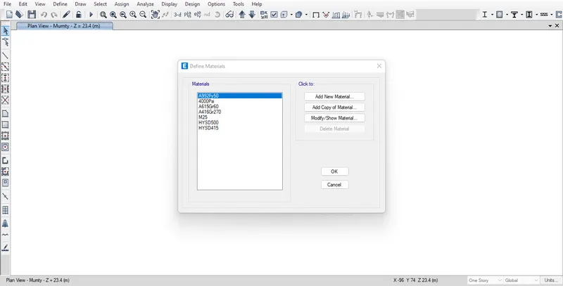
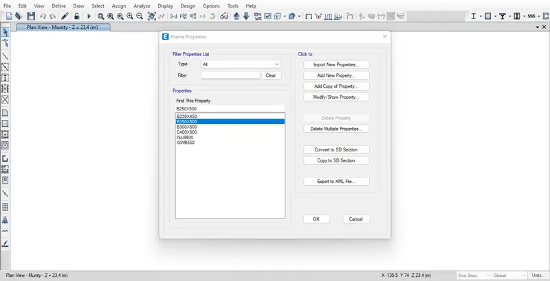
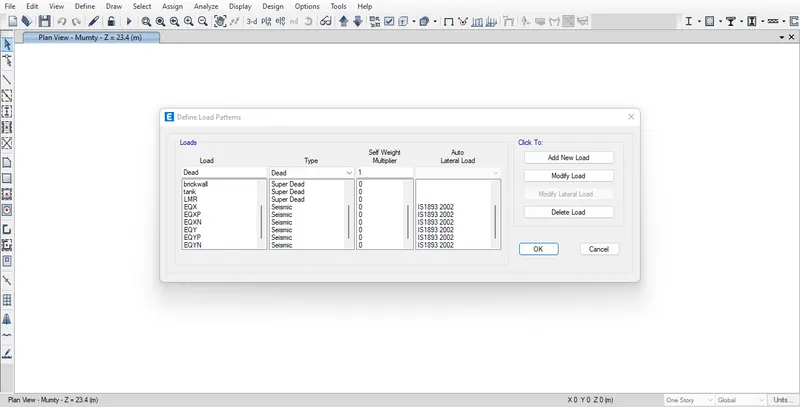
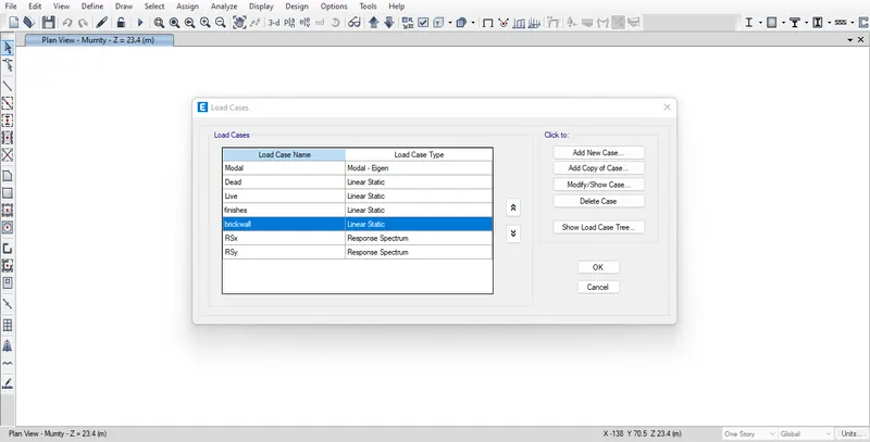
Check after analysis
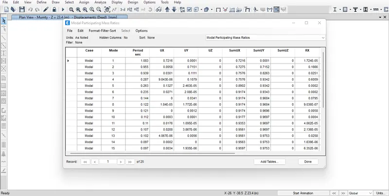
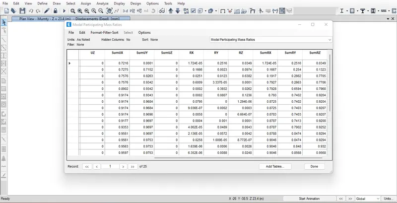
* Modal mass participation for first 3 modes dominates at least 65%(Achieved for X-axis only)
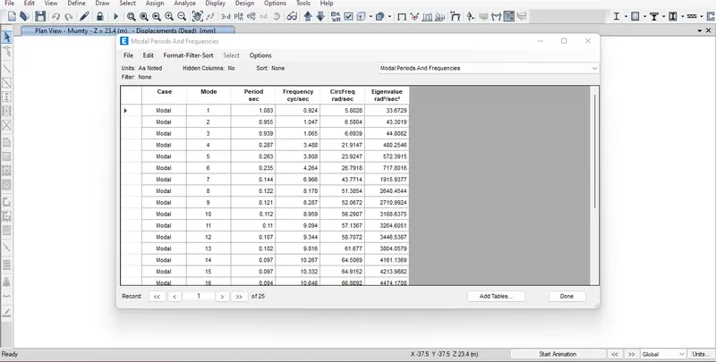
* Mode-1 and Mode-2 differs by 10%(Achieved)
* Principal modes be greater than Torsional mode(Achieved)
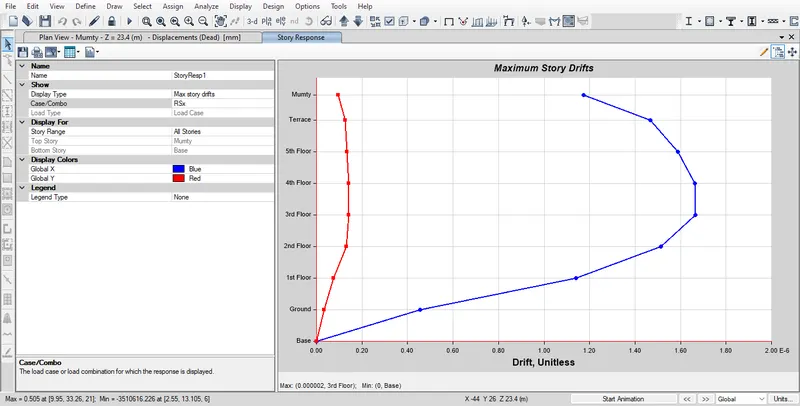
* Inter story drift ratio limited to 0.004(Achieved)
* Axial stress in column and shear wall(Achieved)
* Base shear share between shear wall and columns(Not dual system)
Result :-
Successfully complete the architectural drawings for a G+7 residential building in zone 5 has been provided. The floor plan is the same for all 7 floor levels. Possible column positions have also been provided. Conceptualize a framing plan layout and then model the building in Etabs. The following architectural drawings have been provided:
- Typical floor plan – The location and thickness of the brick walls and the use of the
space (for estimating live load) can be obtained from this plan - A building section through the staircase and lift core is provided
- Parking layout in the ground floor – the column/shear wall arrangement must not
obstruct entry/exit of vehicles.
The following loadings are to be taken into account: - Brickwall made of AAC blocks
- Finishes – floor tiles of 75 mm thickness
- Live loads as per IS 875 part 2
- Water tank of 20 KL above the staircase at Mumty level
- Lift Machine room at mumty level above lift core
The structural model must comply with provisions of IS 1893 and IS 13920.
Run a modal response spectrum analysis and check analysis results of the etabs model for inter-storey drift requirements, vertical & planar irregularities, minimum shear wall requirements,maximum axial load ratio for column and shear walls, effective moment of inertia for beams
and columns etc.
Please note that the column positions shown in the architectural typical floor plan are only to provide an initial starting point for modelling. Participants will have to change its size, introduce shear walls, and add new vertical elements after running the analysis. You will have to run the analysis multiple times until a structural model is obtained that meets structural code requirements without compromising architectural functions. Also, there is no one ‘correct’ structural system for this challenge. There can be multiple possible solutions for this problem.