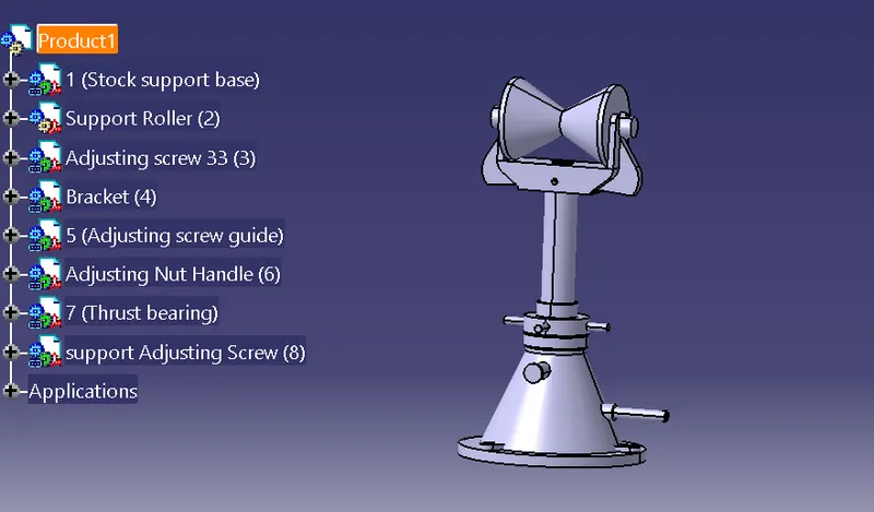
Stock Bracket Assembly : Week 4 Challenge
Stock Support Base: -
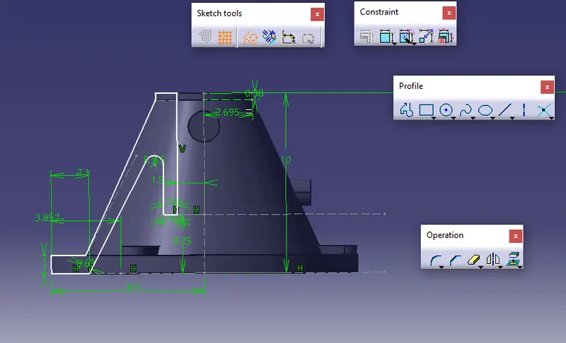
- As shown in section view A-A, one side of the sketch was drawn and then revolved around vertical axis.
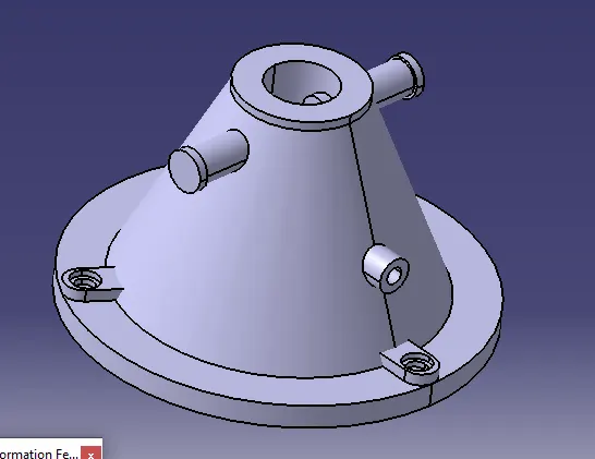
- To make handles shaped part, created a plane at an offset value given in the sketch, drew circle and padded it then another circle on this pad and extruded this up to main surface.
- This was mirrored onto the other side
- Then gave the three nut provisions as shown in the sketch.
- Counterbored in Hole command was used to make counterbored hole.
- Created a new body part to make the hole for screw guide.
- Defined a plane and padded it. then used union trim command to delete the intersection.
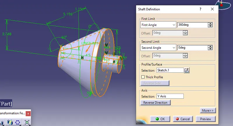
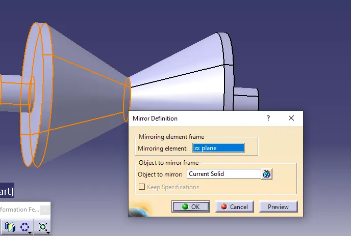
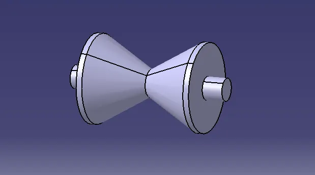
Stock support Roller: -
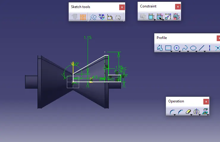
- Sketch was drawn and then revolved it around horizontal axis by using shaft command.
Adjusting screw: -
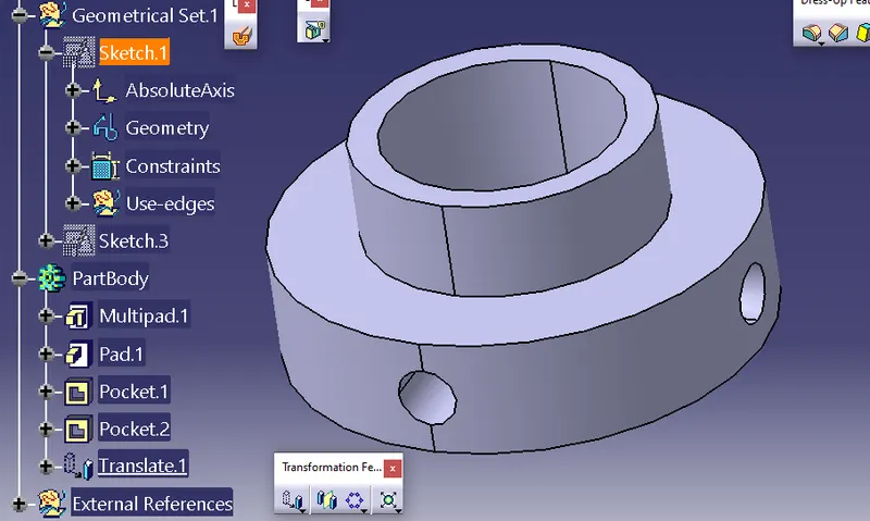
- First made the main body by making its sketch and revoving it.
- Then made the three holes by using pocket command and circular pattern command.
Support roller Bracket: -
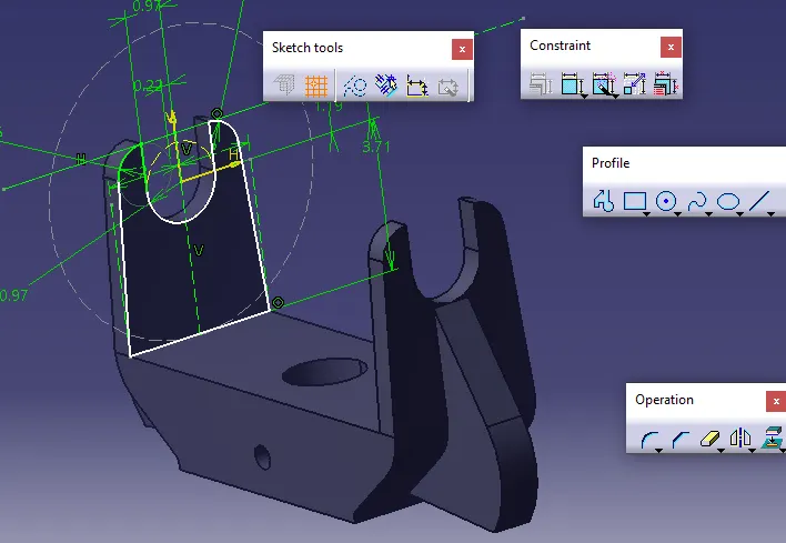
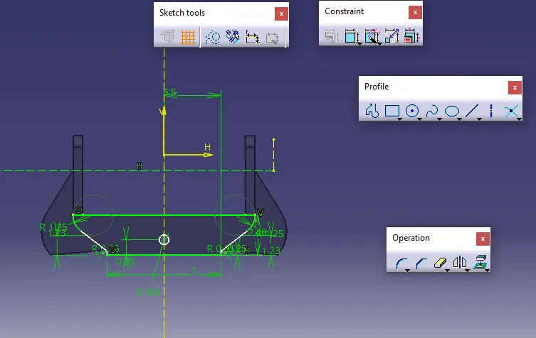
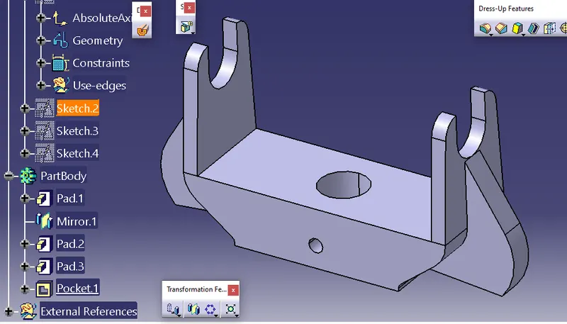
- Main body was made first by making sketch and then padding it
- Then pocket was made on its top surface
- Hook shaped structure was made by making its sketch and padding it
- Support sturctures for roller was made in the end.
- The previous two pads were mirrored onto the other side
Adjusting Screw Guide: -
- Shaft command was used to make the part then chamfering was done at required edges.
- pocket command was used to make rectangular cut on the top face
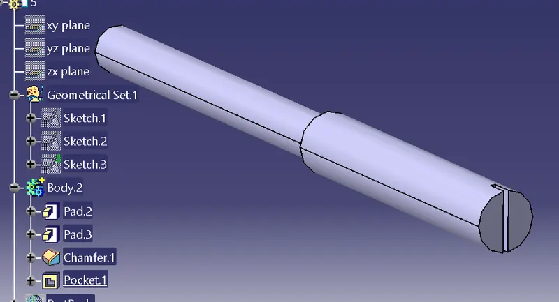
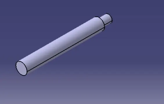
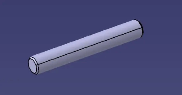
- Adjusting nut handle and support adjusting screw were made in the similar fashion
Thrust: -
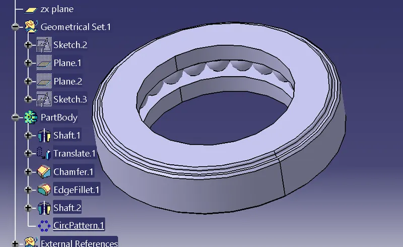
- Sketch was made and then revolved it around vertical axis.
- Then a semi-circular sketch was made in the groove and shafted it around its diametrical axis to make a spere
- This sphere was circular patterned to make multiple number of balls.
Assembly: -
- All the individual parts were assembled in assembly workbench by using offset, coincident, and surface contact constraint