Steady Vs Unsteady flow over a cylinder
OBJECTIVE
To simulate the flow over cylinder and explain the phenomenon of Karmen Vortex street
Part – I
- Simulate the phenomenon for Re = 100 using steady and transient solver. Calculate the value of Strouhal number.
Part – II
- Calculate the drag and lift coefficient over a cylinder for Re = 10, 100, 1000, 10000, 100000 using steady solver.
- Discuss the effect of Reynolds number on drag coefficient.
THEORY
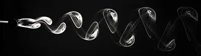
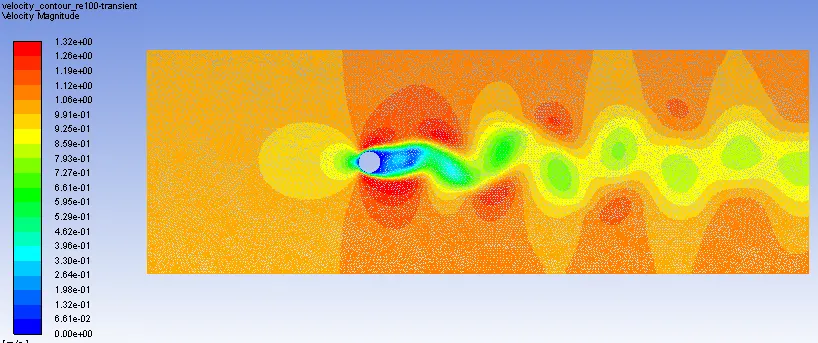
In fluid dynamics, a Karmen vortex street is a repeating pattern of swirling vortices, caused by a process known as vortex shedding, which is responsible for the unsteady separation of flow of a fluid.
In the wake region of a body, the flow consists of an alternating system of vortices. If the vortices on the top region are rotating clockwise then in the bottom the vortices are rotating counter clockwise and vice versa.
The phenomenon is significant with increase in Reynolds number of the flow.
PROCEDURE
Brief procedure followed to setup different simulations
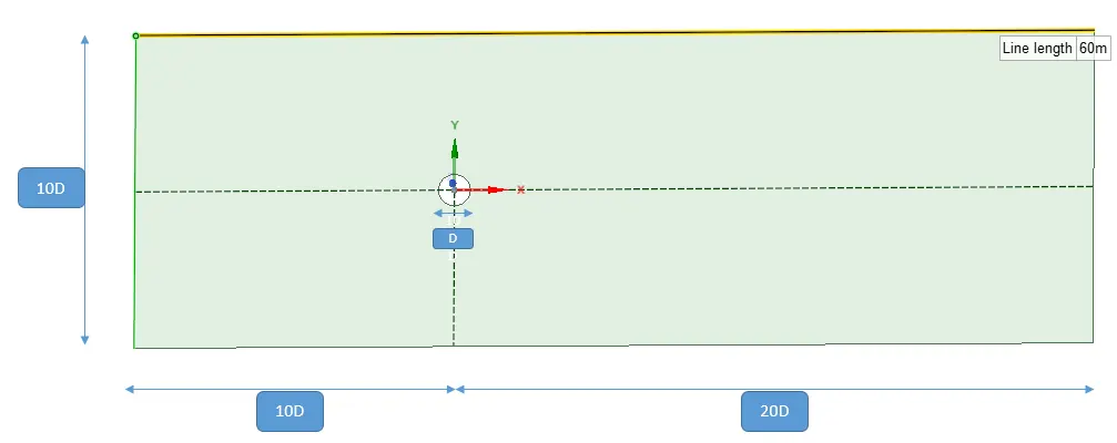
Geometry setup – creating the cylinder and then defining the surrounding region
Mesh – different mesh option are used to get a refined mesh.
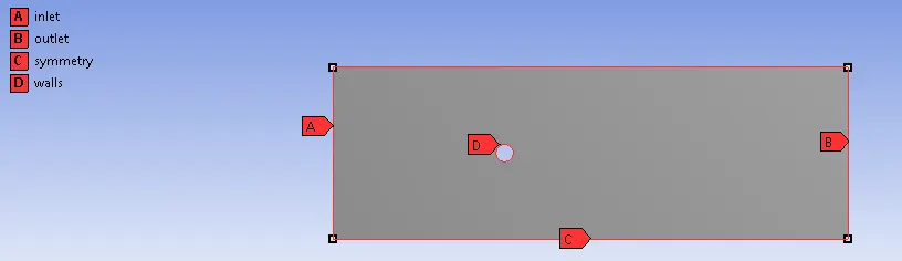
- Insert -> method -> trias. To get the tria elements
- Insert -> edge sizing -> select cylinder walls -> no of elements = 36 (10 degrees for each element)
- Insert -> inflation -> select geometry -> select boundary -> first layer thickness = 0.005m -> no of inflation layers -> 6
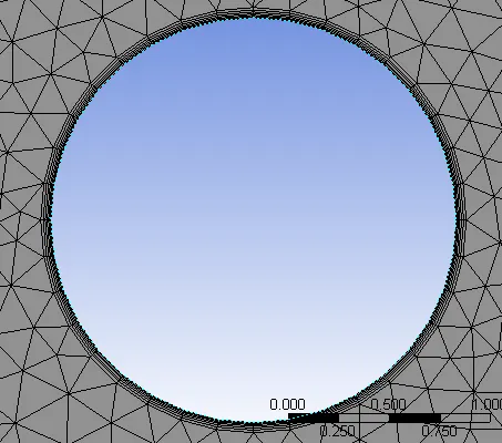
- Mesh element size = 0.1 m
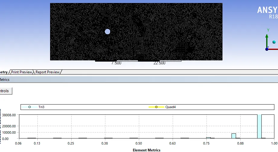
Nodes - 23885
Elements - 46718
Setting up physics – different steps involved in setting up simulation
- General -> Steady/Transient -> pressure based solver (incompressible flow)
- Model -> Laminar (low Reynolds no)
- Material – We will control the Reynolds number using the viscosity of the flow. So new material is created defining density =1 and viscosity.
- Boundary Condition -> inlet velocity = 1 m/s, outlet = pressure -> gauge pressure =0
- Definition -> Drag coefficient, Lift coefficient and vertex averaged velocity
- Initialization -> Hybrid initialization (to create initial conditions in our geometry)
- Activity -> solution animation (to setup velocity animation to track the vortex shedding phenomenon)
Solve -> Run calculation (enter no of iteration/timestep)
PART – I Run a simulation for Re = 100 using Steady and transient solve. Calculate Strouhal number
Steady Solver - Input – Velocity – 1m/s, Re = 100, D = 2, density = 1 so viscosity = 0.02
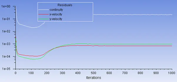
The solution starts to converge at around 500 - 600 iteration. Vortices are formed beyond the cylinder
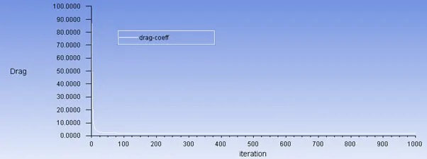
drag coefficient: 1.6048
lift coefficient: 0.0197
residual plots
Drag and lift coefficients

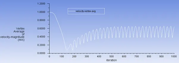
Vertex velocity average
Velocity and pressure contour
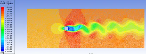
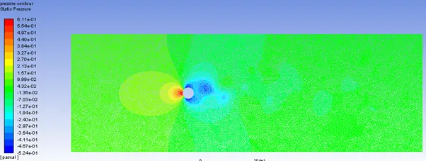
Transient Solver - Input – Velocity – 1m/s, Re = 100, D = 2, density = 1 so viscosity = 0.02
Time step = 0.1
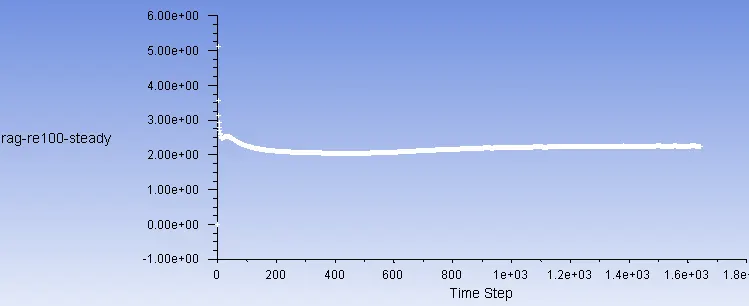
Drag coefficient = 2.08005
lift coefficient = 0.11160
Residual Plot
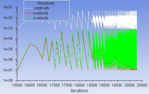
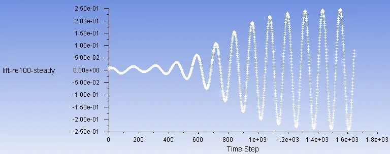
Drag and lift coefficient
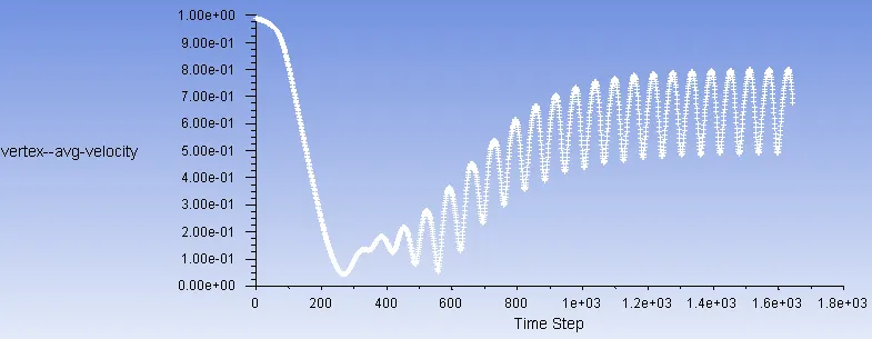
Vertex velocity average
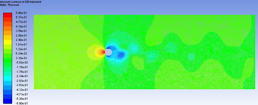
Velocity and Pressure Contour
STROUHAL Number
The Strouhal number is a dimensionless number describing oscillating flow mechanisms. The Strouhal number represents the ratio of inertial forces due to the local acceleration of the flow to the inertial forces due to the convective acceleration.

f= frequency, L = length, U = Free stream velocity
Since this is a time dependent quantity, the value for strouhal number is only possible in case of transient simulation. So for Transient simulation with Re = 100 and time step = 0.1, the strouhal number gives the value of strouhal no.
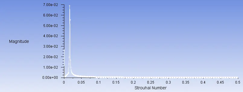
Strohal Number = 0.016
Part - 2 Calculate drag and lift coefficient for Re = 10, 100, 1000, 10000, 100000
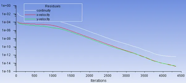
RE = 10, viscosity = 0.2
residual plots
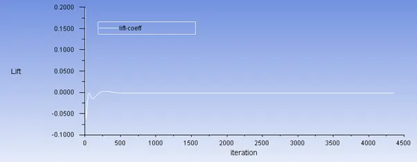
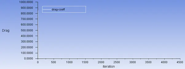
Drag and Lift coefficients
Velocity and pressure contour
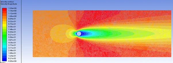
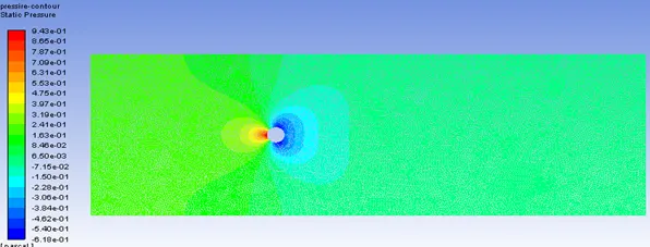
It can be seen from above images that although the residual are way below the convergence criteria, solution has not converge. Even Value of drag coefficient is very high and thus vortex shedding doesn't take place at such low reynolds number.
RE= 100, viscosity = 0.02
discussed above
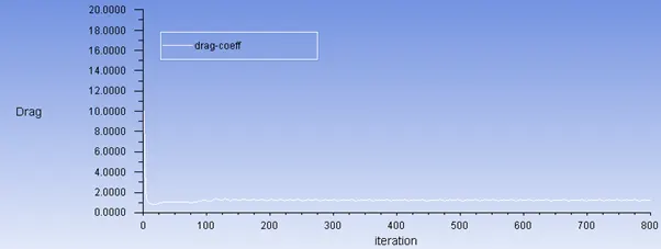
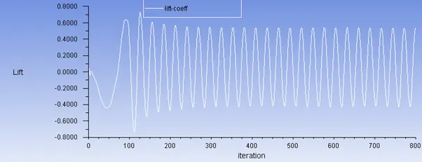
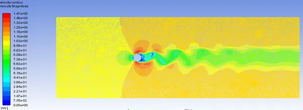
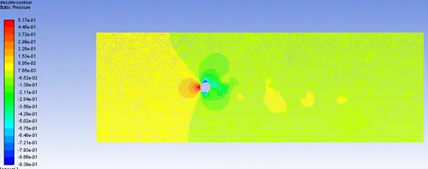
Re = 1000, viscosity = 0.002
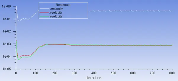
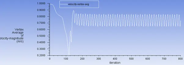
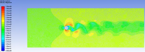
The solution starts to converge at around 300 iteration. Vortices are formed beyond the cylinder
residual plots
vertex velocity average
Drag and lift coefficients
Velcoity and pressure contour
Re = 10000, viscosity = 0.0002
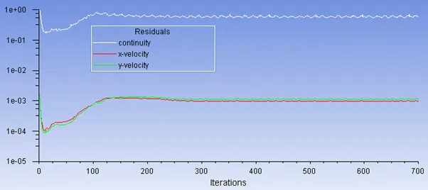
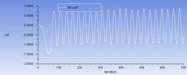
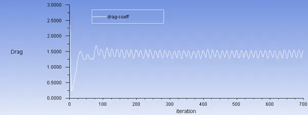
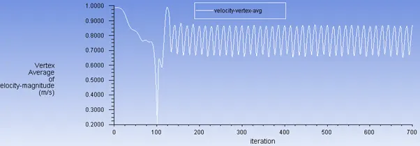
The solution starts to converge at around 200 iteration. Vortices are formed beyond the cylinder
residual plot
Drag and lift coefficients
vertex velocity average
Velocity and pressure contour
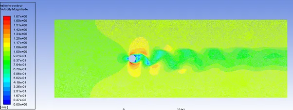
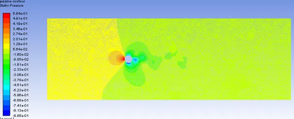
Re = 100000, viscosity = 0.00002
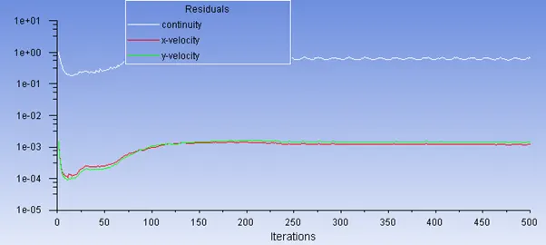
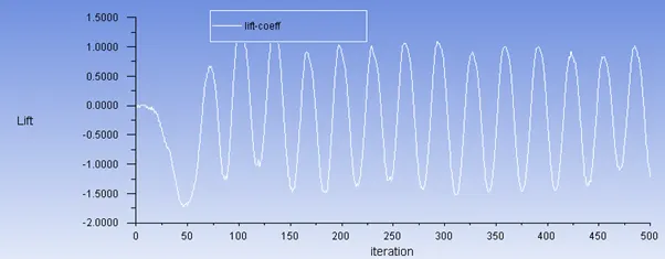
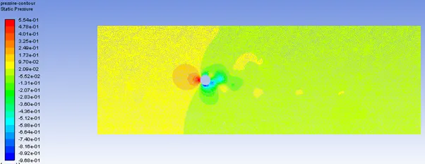
The solution starts to converge at around 150 - 200 iteration. Vortices are formed beyond the cylinder
residual plot
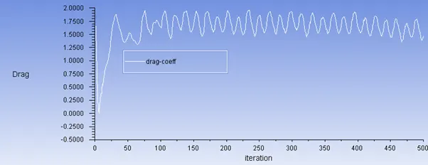
lift and drag coefficient
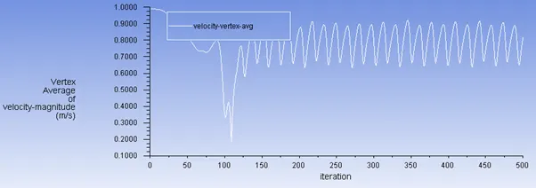
vertex velocity average
velocity and pressure contour
|
Re |
cd |
cl |
velocity |
|
10 |
5.4318007 |
-0.001292089 |
0.42371792 |
|
100 steady |
1.6048 |
0.019703128 |
0.64222336 |
|
1000 |
1.5367994 |
0.53125112 |
0.73625898 |
|
10000 |
1.5233681 |
-0.61685817 |
0.8689456 |
|
100000 |
1.4566432 |
-1.2129731 |
0.81473446 |
From the above results we can say that as the reynolds number increases the value of drag coeffcient decreases. This is due to the dominance of inertia forces over viscous force and as a result the formation of vortices is more dominant
NOTE: the value of lift varies between the negative and positive values as the inlet flow is symmetric along the axis of the object and upon contact with cylinder is dispersed in two similar components one acting downward and one acting upward. Thus negative value signifies that the force is acting downward
CONCLUSION
- Both steady and transient solver are used in the study. It shows that the results obtained by transient solver are more detailed as compared to steady
- Vortex shedding becomes dominant with increase in reynolds number. At lower reynolds number, the convergence is very difficult (in case of Re =10)
- Drag coefficient devreases with increases in reynolds number
- As the reynolds number increase, in this case the convergence is faster.