Sketch a G+1 residential plan according to Vaastu Shastra and Calculation of Loads as per IS code
Sketch a G+1 floor residential plan, according to Vaastu Shastra, and list down the names of the structural drawings required to be provided to the site for construction.
Also, assume the sizes of the structural elements (Column, Beam, Slab, etc.,) and accordingly calculate the individual corresponding loads from the members as per IS code.
AIM
- To prepare a G+1 Residential Building plan According to vaastu shastra
- To Calculate the different load according to the individual members of the structure Elemets as per IS Codal Provision
INTRODUCTION
- vaastu Shastra is popular across the world. The reason behind this is the universal need for peace and harmony
- The application of Vaastu Shastra in home construction and design is supposed to bring along with promises of good health, wealth and happiness in life.
- Vaastu shastra is the ancient Indian science of architecture and acts as a guideline to design your home in a way that enhances positive energy.
- Our nature is abundant with powerhouses of energy sources like the sun, wind, moon, water, earth, and fire
- Effects of sunrays, the flow of winds, pull of earth's magnetic field, and other such cosmic energies
Vaastu shastra:
- Vaastu shastra is the ancient Indian science of architecture and acts as a guideline to design your home in a way that enhances positive energy.
- Our nature is abundant with powerhouses of energy sources like the sun, wind, moon, water, earth, and fire
- Effects of sunrays, the flow of winds, pull of earth's magnetic field, and other such cosmic energies
- A good home needs to radiate the right kind of energy.
- A person dwelling in a house comes under the influence of a specific energy field.
- Architectural changes are not possible for a ready-to-move-in house.
Ideal directions:
- Preferable direction for entrance is north, east can be preferred.
- Northwest is ideal for living rooms
- Idols are placed in the northeast
- Southeast is ideal for kitchen
- Southwest is ideal for storage.
- Significance of four directions:
- Four cardinal directions are north, south, east, and west.
- Four intercardinal directions are north-east, north-west, south-east, and south-west,
- Each direction signifies an aspect of life and is governed by various gods.
- North-wealth
- South-Dharm
- West and east - overall prosperity
The basic principle of Vaastu shastra:
- Shape: Rooms should preferably be square or rectangular.
- Room basics: The room should be airy, well-lit, bright, and clean.
- Home center: Centre of the house should be a space.
- Stairs and furniture: Heavy furniture should be kept in the southwest direction.
- Water: Avoid keeping paints and water features in the bedroom.
- Dining table: The dining space should be near the kitchen and not near the main door.
- Mirror placement: Mirror facing the bed is strictly not allowed. Mirrors in the bedroom need
- to be placed in such a way that the bed cannot be seen.
Auspicious directions as per Vaastu shastra:
- Kitchen: South-east is the best, northeast to be avoided.
- Staircase: South-west is the best, northeast to be avoided.
- Toilet: North-west is the best, northeast to be avoided.
- Master bedroom: Southwest is preferred.
- Guest room: North-west is preferred.
- Living room: North-west is preferred.
- Overhead tanks: West is the best
- Underground tanks: Northeast is preferred, Southwest to be avoided.
- Gateway (entrance) of the house:
Positive energy can be attached to the right entrance of the house.
Pooja room:
- East or northeast part of your home is perfect for meditation, yoga, and spiritual pursuits
- Facing east when you meditate will increase positivity.
- Create a sacred altar and decorate it with candles or incense sticks
Kitchen:
- Keep the water sink away from the gas stove.
- The fridge needs to be placed in the southwest corner.
- Never let your kitchen face a washroom wall or share a common wall with it.
Study room:
- Select a square or rectangle shape for the study table.
- Don't place the table facing a blank wall or window.
- Placing the table in the northeast, east, or west direction is ideal.
- Hanging bookshelves are best avoided.
Courtyard:
- Brahmasthan is a unique feature of ancient architecture based on Vaastu Shastra.
- It is the center of your residence and the holiest and most powerful zone.
- In a traditional home in Kerala, the courtyard is always at the center of the house.
- This part should be perfect and clutter-free.
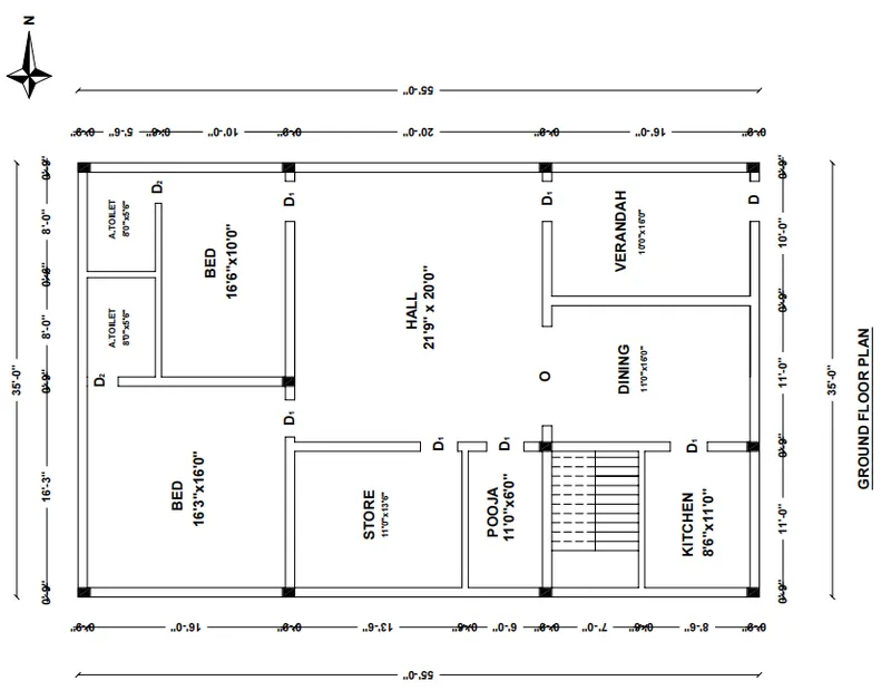
GROUND FLOOR PLAN - EAST FACING G+1 BUILDING
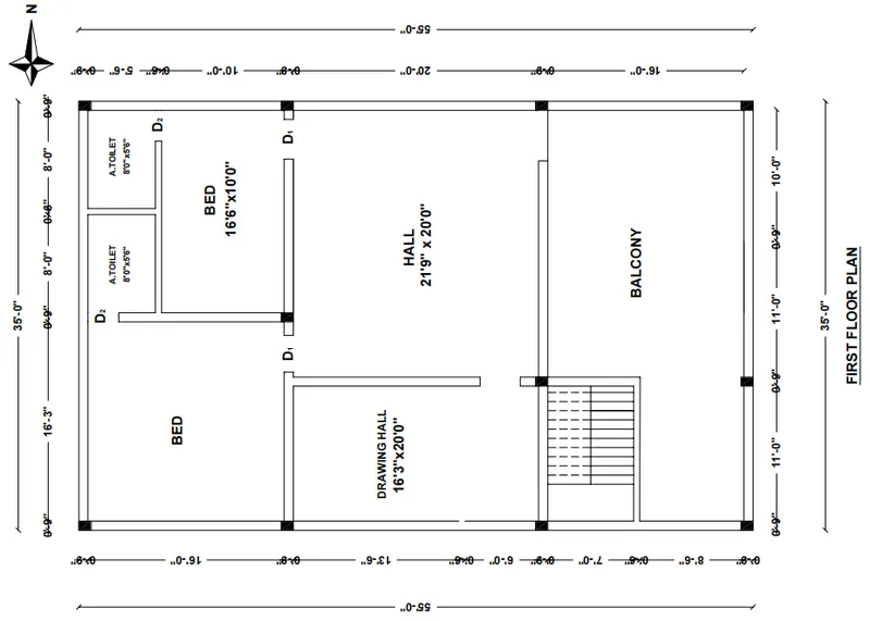
FIRST FLOOR PLAN - EAST FACING G+1 BUILDING
STRUCTURAL DRAWINGS REQUIRED TO BE PROVIDED
Centre line drawing:
- Centre line drawing provides the grid formation by dividing the plan into a number of grids.
- It is the very first structural layout diagram prepared by the engineer.
- It is called center line drawing.
- It helps in marking the buildings, columns, footing, and other structural elements.
- Based on the center line diagram, excavation of soil for the footing is done.
- The dimension of columns and grids are also shown.
Structural detailing for Footings and Columns:
- This structural diagram shows both column and pedestal details with the markings and dimensions.
- Thickness, column numberings, footing dimensions, and details, and PCC details in all the directions are shown.
- The footing should not be overlapped and it should be replanned if needed.
- The concentric and eccentric column footing has to be done as per the requirement.
- Column Layouts are used for erecting columns on site as per project design
- These are referred onto the site for marking column placement, size and specifications of details of the column design.
Column schedule with reinforcement details:
- This shows the reinforcement details such as the diameter of bars, covers, spacing, location, and stirrups.
- The footing section consists of the thickness of sand filling, PCC thickness, PCC extension, reinforcement details such as crank, and a number of column ties.
- The sectional elevation is to be shown for all grouped columns. The typical column and footing structural rebars details have to show.
Plinth beam layout with reinforcement details:
- This reinforcing layout has to show the plinth-level beam details connected with columns.
- The size of the plinth beam, the diameter of the bars, thickness, grid-to-grid dimension, crank details, and column dimensions should be shown.
- The size of the plinth beam used should be mentioned.
Roof Beam with Reinforcement details
- It includes the layout of roof slabs concerning the corresponding beam by the Centreline Grid Markings of Columns-Beams.
- This involves the orientation of the roof slab and Reinforcement Bar Details to be incorporated according to Structural Design.
- Details like diameter and number of reinforcement bars in a defined length are mentioned in roof slab layout for structural stability.
First-floor slab layout with reinforcement details:
- These reinforcement details have to show the details of the sunken slab and 10 inches below the floor level.
- It will be provided in bathroom areas.
- The thickness and respective dimensions of the slabs are to be shown.
Elevation and headroom reinforcement details:
- It will be provided with RC elements and plain cement concrete as footing and waterproofing areas should be shown.
- If a lift is provided a beam should be provided at the roof slab level and a lintel beam below the roof.
- This layout is a mandated one.
- Lintel beam is to be shown with all structural arrangements.
Electrical Works Drawing and Schedule
- General Symbols, notations and details are mentioned as a separate legend for reference.
- Major inclusions are Electrical Legend, Lighting Plans, Wiring Plans and Details, Equivalency Chart, Switch-Equipment Legend.
- These Drawings represent equipment/appliance positions, Switch-Board locations through referential grid and detailed dimensions in the layout of the building.
Water Supply and Plumbing
- Plumbing Schedule: List of Plumbing Fixtures with sizes, number, Brand, Typology etc.
- Constructional Details depicting fixing positions with dimensions with reference to wall planes.
- Water Supply Layout: Inlet and Outlet pipes of various fixtures depicting water flow and slopes.
- Manhole Schedule and Layout: Manhole position with nomenclature and sizes.
- Sewerage Management Plan: Plans depicting pipelines for discharge management with sizes and slope of inclination of pipes.
- Rainwater Layout Plan: drawings depicting rainwater discharge management/harvesting from roof planes to underground level.
AIM
- To Calculate the different load according to the individual members of the structure Elemets as per IS Codal Provision
INTRODUCTION
- Dead Load is constant load in a structure (such as a bridge, building, or machine) that is due to the weight of the members, the supported structure, and permanent attachments or accessories
- That’s Refers as per IS Codal Provision of IS 875 Part I
- Live loads are those loads produced by the use and occupancy of a building or structure and do not include construction loads, environmental loads
- That’s Refers as per IS Codal Provision of IS 875 Part II
- Wind loads is the load, in pounds per square foot, placed on the exterior of a structure by wind. This will depend on: The angle at which the wind strikes the structure. The shape of the structure
- Wind load consider for the height of the building above 10m
- That’s Refers as per IS Codal Provision of IS 875 Part III
Calculation of Loads in the Structure
Dead Load
Dead Load calculation for Hall Size 7m x 6m as per IS Code 875 part I
- All columns are 300 mm x 450 mm
All beams are 300 mm x 300 mm for Longer side of slab in hall
Slab Thickness is 125mm for Hall size 7m x 6m
The height of the wall is 3.5 m and 230mm Thickness
- Dead Load of Column = 0.3 x 0.45 x 3.5 x 25 = 11.813 kN
- Dead Load of Beam = 0.3 x 0.3 x 7.0 x 25 = 15.75 kN
- Dead Load of Slab = 7.0 x 6.0 x 0.125 x 25 = 131.25 kN
- Dead load of Wall = 0.23 x 3.5 x 7.0 x 20 = 112.70 kN
Live Load
As per the IS code 875 Part II
Live loads are followed as,
- Kitchen = 2 kN/m2
- Living Room = 2 kN/m2
- Store Room = 2 kN/m2
- Toilet = 2 kN/m2
- Staircase = 3 kN/m2
- Balconies = 3 kN/m2
- Bed Rooms = 2 kN/m2
Wind Load
As per the IS code 875 Part III
Wind Load considered only for the Building of height above 10m . below 10m height wind load is negligible.