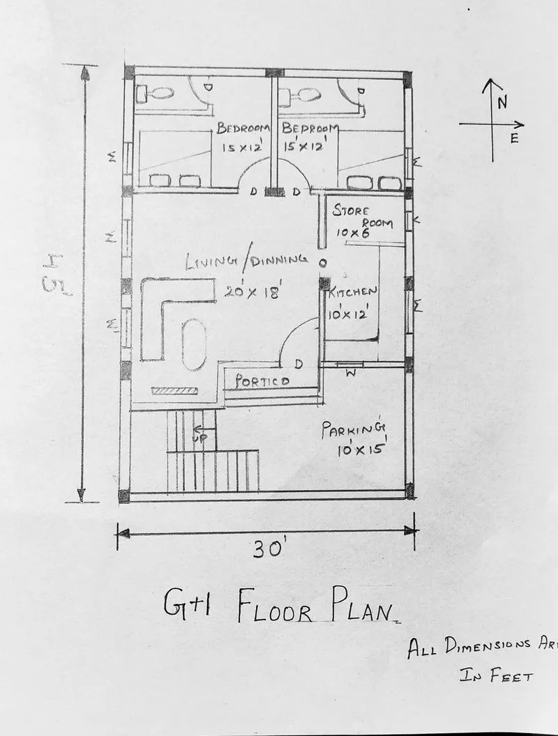
Sketch a G+1 residential plan according to Vaastu Shastra and Calculation of Loads as per IS code
1) LIST OF DRAWING TO BE PROVIDED AT SITE
- Centre line drawing
- Footing and column layout with reinforcement details
- Column schedule with reinforcement details
- Plinth beam layout with reinforcement details
- First floor beam layout with reinforcement details
- First floor slab layout with reinforcement details
- Lift pit and head room reinforcement details
STRUCTURAL NOTES to be followed in all drawing
- Written dimension Is followed
- Grade of concrete
- Clear cover to reinforcement
- Deshuttering
- Minimum curing time
- Printing size in A3 for better clarity
- Pointing Direction
- Drawn by, checked by, designed by,
- Project name
- Client name
- Architectural consultant
- Drawing title
- Structural design consultant
CENTRE LINE DRAWING
- This type of drawing Is used to marking the column position and footing at the site.
- And can be used for excavating the soil at the site.
- This drawing provides the grid position with the dimension to followed.
- This drawing easy to mark the centre position at the site.
- This is first drawing issued at the site at the beginning of the project.
FOOTING AND COLUMN DETAILS
- The same pattern of the center line drawing with column and footing reinforcement details
- The center line should show the footing width and breath size of the footing as per the column requirement.
- If there is any clash between the columns so we have to reduce the size of the footing as per the requirement.
COLUMN SHEDULE WITH REINFORCEMENT DETAILS
- THIS drawing provides the section of the footing and column reinforcement details.
- Like how much crank should needed for the column and how many lateral ties to be followed in bottom of the footing.
- Column reinforcement with detailed mentioned how much of dia bar is used
- Footing reinforcement with detailed c/c reinforcement and how many dia bars is used.
PLINTH BEAM LAYOUT WITH REINFORCEMNET DETAILS
- This drawing shows the plint beam connecting to column from the ground level.
- This drawing shows the reinforcement details with detailed.
- Main thing is to be noted is numbering of plinth beam according to sizes.
- Section of beam reinforment should be mentioned.
FIRST FLOOR SLAB LAYOUT WITH DETAILED REINFOREMENT
- This drawing should contains the beam and slab reinforcement layout as per requirement.
- We have note that if there a sunken slab so that we have to mention by separate pattern
- If there is a sunken slab there will be no crank in sunken slab.
- In the slab the crank should be clearly visible to the layout.
- Mention the dia of bar in main reinforcement and distribution bar and spacing of bars.
Lift PIT HEAD REINFORCEMENT
- THE lift hooks should be considered while planning the reinforcement details for the lift and head room.
as per IS CODE 875 ;1987 revised 2018(part 1) for dead load is mentioned.
individual members of the building
1) calculation of dead load of a column
Dead load of a column
ASSUMED
- Total volume of concrete = 0.45*0.50*3m = 0.675 m^3
- Unit weight of concrete = 25 kn/m^3
- Dead load of column = 25*1.215 = 16.87 KN
2) calculation of wall load on beam
Calculation of Wall load on a beam of height 3m
ASSUMED
- Height of the wall = 3m
- Thick of wall = 230mm
- Unit weight of brick wall = 20kn/ m ^3
- Dead load of wall = 20*3*0.23= 13.8Kn/m
3) SELF WEIGHT OF BEAM
ASSUMED
- Beam 0.4*0.50*5*25 =25 Kn/m3
4) SELF WEIGHT OF SLAB
ASSUMED
- Span = 4m*4m*0.25m
Sol
Self weight = 4*4*0.25= 4kn/m3
Dead load = 4*25 = 100kn/m3
as per IS CODE 875 1987 revised 2008(part 2) for live load is mentioned
LIVE LOAD of rooms
- For kitchen = 2 kn/m2
- Bathroom = 2 kn/m2
- Bedroom = 2 kn/m2
- Store room = 3 kn/m2
- Living and dining = 2 kn/m2
- Terrace = 3 kn/m2
WIND LOAD
wind load is not necessary. hence the height of the building is less than 10 m.