Drafting of various geometries using Chamfer, Fillet tool in AutoCad
1)AIM
TO draw the following figure using autocad.
INTRODUCTION
This drawing is created using autocad and the procedure is explained in detail in each steps and the commands are used in this drawing are.
COMMANDS USED
- L- LINE
- F8- ORTHO MODE
- GRIDMODE
- F10 - POLAR TRACKING
- C- CIRCLE
PROCEDURE
- open autocad file in windows desktop.
- a dialog box will open it shows startup from scratch.
- click the radio button imperial to start the project.
- in command box type gridmode to show the gridmode by typing 1 in the command box
- press F8 to get ortho on
STEP 1
Type L in the command box for LINE
- Specify first point type (1,1) in the command box and press enter.
- Specify next point as 3 and press enter.
- Specify next point type @2.12<45 and press enter.
- Specify next point type @2.83<135 and press enter.
- Specify next point type 2.00 and press enter.
- Specify next point type c for close to complete.
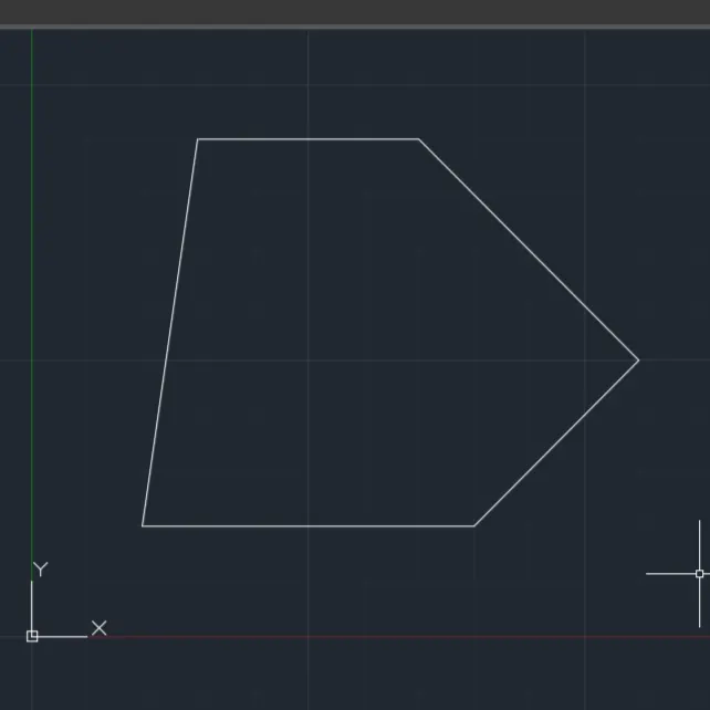
STEP 2
type c for circle in the command box
- specify centre point of the circle at 1.50,1 and press enter
- specify radius of the circle press diameter 1.20 and press enter.
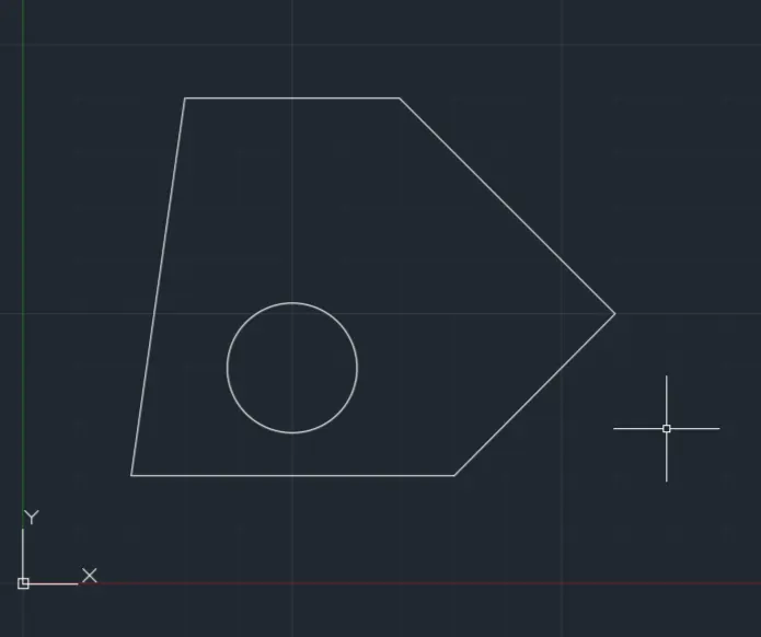
STEP 3
type c for circle in the command box
- specify centre point of the circle at 1.50,2.50 and press enter
- specify radius of the circle press diameter 0.8 and press enter.
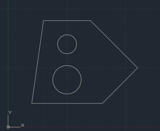
RESULT : The following figure is done as per dimension is completed.
2)
AIM
TO draw the following figure using autocad.
INTRODUCTION
This drawing is created using autocad and the procedure is explained in detail in each steps and the commands are used in this drawing are.
COMMANDS USED
- L- LINE
- F8- ORTHO MODE
- GRIDMODE
- F10 - POLAR TRACKING
- C- CIRCLE
- M-MOVE
- RO-ROTATE
- TR-TRIM
PROCEDURE
- open autocad file in windows desktop.
- a dialog box will open it shows startup from scratch.
- click the radio button imperial to start the project.
- in command box type gridmode to show the gridmode by typing 1 in the command box
- press F8 to get ortho on
- Type units press engineering to change the units.
- press the architectural button.
STEP 1
COMMAND - L- LINE
- specify the first point at any point.
- specify the next point 8' and press enter.
- specify the next point 1'9'' and press enter.
- specify the point 2'5'' and press enter.
- press F10 for polar traking on
- specify the next line 2'10'' at an angle 135 degree.
- specify the next draw horizontally to meet the other line. and press enter.
- draw a line in separate space to meet the horizontal line. at a angle of 90 degree and press enter.
- command - M- MOVE
- move the object to meet the vertical line 2'5'' and press enter
- command - RO- ROTATE
- rotate the object until it meet the horizontall line and press enter.
- command - TR -TRIM
- trim the object which is not necessary and press enter.
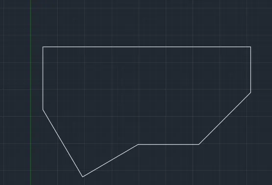
RESULT : The following figure is done as per dimension is completed.
3)
AIM
TO draw the following figure using autocad.
INTRODUCTION
This drawing is created using autocad and the procedure is explained in detail in each steps and the commands are used in this drawing are.
COMMANDS USED
- L- LINE
- F8- ORTHO MODE
- GRIDMODE
- F10 - POLAR TRACKING
- C- CIRCLE
PROCEDURE
- open autocad file in windows desktop.
- a dialog box will open it shows startup from scratch.
- click the radio button imperial to start the project.
- in command box type gridmode to show the gridmode by typing 1 in the command box
- press F8 to get ortho on
- Type units press engineering to change the units.
Type L for line command box.
- Specify first point: (1.1) and press enter.
- Specify next point 1'6 and press enter.
- Specify next point 5'0.1 and press enter.
- Specify next point 3'3and press enter.
- Specify next point 2'6.5and press enter.
- Specify next point c to Close
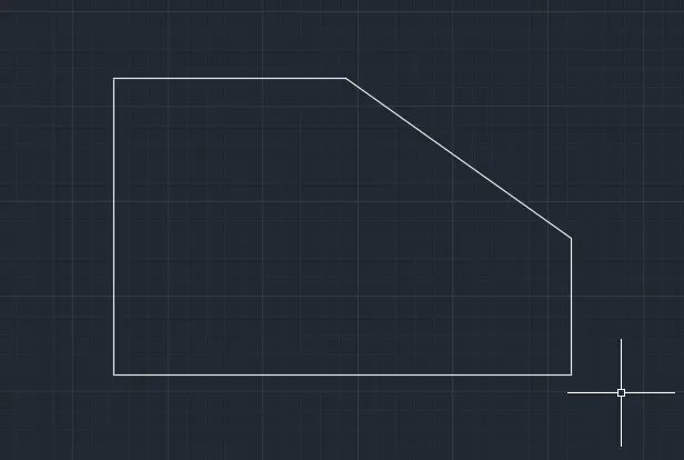
Type C for circle and press enter
- specify the first point (1'3'',1'6'')of the center and press enter.
- specify the second point press diameter 1'6'' and press enter.
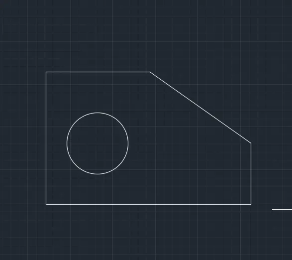
RESULT : THE following figure is done as per dimension is completed.
4)
AIM
TO draw the following figure using autocad.
INTRODUCTION
This drawing is created using autocad and the procedure is explained in detail in each steps and the commands are used in this drawing are.
COMMANDS USED
- L- LINE
- F8- ORTHO MODE
- GRIDMODE
- F10 - POLAR TRACKING
- C- CIRCLE
PROCEDURE
- open autocad file in windows desktop.
- a dialog box will open it shows startup from scratch.
- click the radio button imperial to start the project.
- in command box type gridmode to show the gridmode by typing 1 in the command box
- press F8 to get ortho on
- Type units press decimal to change the units.
STEP 1
- Specify first point: 1,1 and press enter.
- Specify next point 3.00 and press enter.
- Specify next point 0.50 and press enter.
- Specify next point 2.50 and press enter.
- Specify next point 2.50 and press enter.
- Specify next point 2.00 and press enter.
- Specify next point 3.00 and press enter.
- Specify next point 2.50 and press enter.
- Specify next point 2.00 and press enter.
- Specify next point 0.50 and press enter.
- Specify next point c to close.
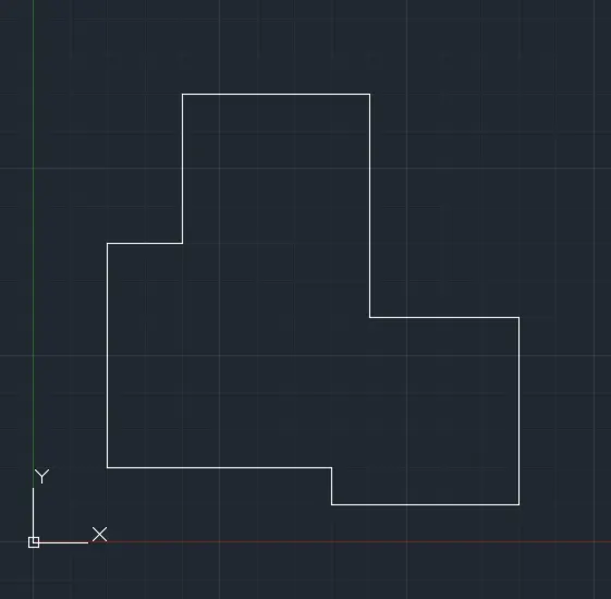
RESULT ; The following figure is done as per dimension is completed.
5)
AIM
TO draw the following figure using autocad.
INTRODUCTION
This drawing is created using autocad and the procedure is explained in detail in each steps and the commands are used in this drawing are.
COMMANDS USED
- L- LINE
- F8- ORTHO MODE
- GRIDMODE
- F10 - POLAR TRACKING
- C- CIRCLE
- M-MOVE
- RO-ROTATE
- TR-TRIM
- O-OFFSET
PROCEDURE
- open autocad file in windows desktop.
- a dialog box will open it shows startup from scratch.
- click the radio button imperial to start the project.
- in command box type gridmode to show the gridmode by typing 1 in the command box
- press F8 to get ortho on
- Type units press decimal to change the units.
STEP 1
Type REC for rectangle
- specify the first point 1,1 and press enter.
- specify the next point 11.50,6.00 and press enter.
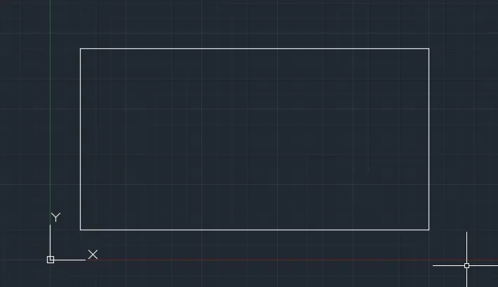
STEP 2
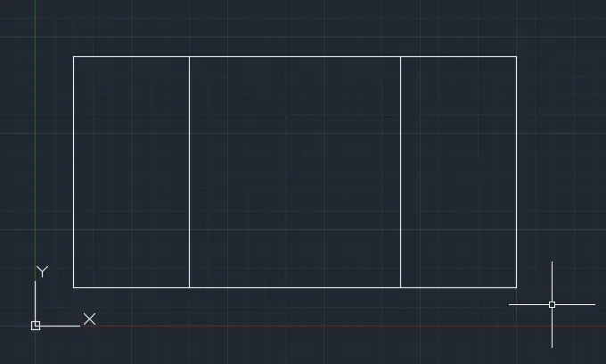
Type L for line in the command box.
- press object sanp for the midpoint of the rectangle.
- specify the midpoint of the rectangle.
- draw a line in the midpoint
- type o for offset 2.75 to the right side of the rectangle.
- press the object to offset again to left side of the rectangle.
- type erase the center line of the midpoint.
STEP 3
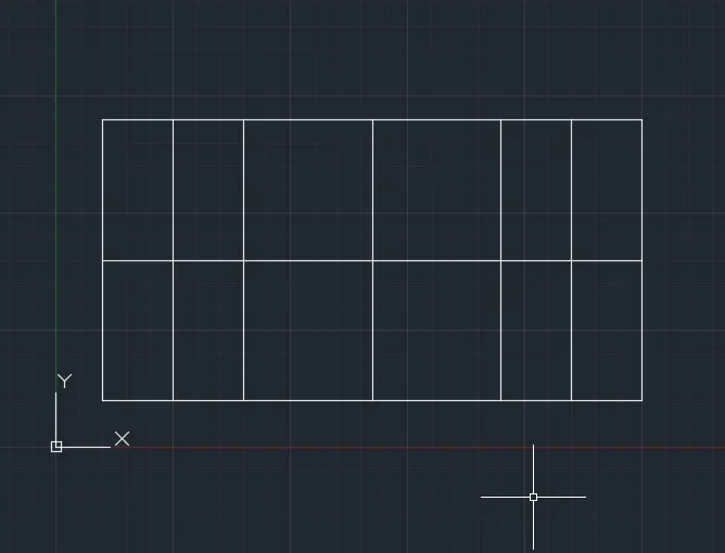
TYPE L for line command in the box.
- specify the line in the midpoint 5.75 and press enter
- type offset command type 4.25 and press enter.
- specify the next point 4.25 to the left side of the rectandle and press enter.
- specify the next line in the vertical direction 3.00 to the midpoint and press enter.
STEP 4
type c for circle command
- specify the first point of the center 3,1.50 and press enter.
- specify the first point as diameter 1 and press enter.
- specify the second circle as diametr 2 and press enter.
- type co for copy command point the center of the two circle and copy the right side of the rectangle'
- type c for circle command to the center of the midpoint as diameter 3 and press enter.
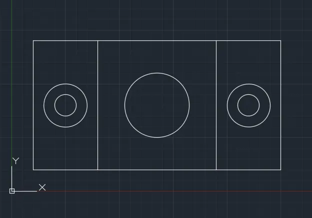
RESULT; THE following figure is done as per dimension is completed.
6)
AIM
TO draw the following figure using autocad.
INTRODUCTION
This drawing is created using autocad and the procedure is explained in detail in each steps and the commands are used in this drawing are.
COMMANDS USED
- L- LINE
- F8- ORTHO MODE
- GRIDMODE
- F10 - POLAR TRACKING
- C- CIRCLE
- M-MOVE
- RO-ROTATE
- TR-TRIM
- O-OFFSET
PROCEDURE
- open autocad file in windows desktop.
- a dialog box will open it shows startup from scratch.
- click the radio button imperial to start the project.
- in command box type gridmode to show the gridmode by typing 1 in the command box
- press F8 to get ortho on
- Type units press decimal to change the units.
STEP 1
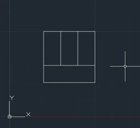
RECTANGE
- Specify first corner point 1,1 and press enter.
- Specify other corner point @1.5,1.5 and press enter.
- Type L for LINE in the command box
- Specify first point: .5 and press enter.
- specify the next point .5 and press enter.
- Specify next point press esc to Cancel.
STEP 2
TYPE L FOR LINE
- Specify first point:
- Specify next point 2.0 and press enter.
- Specify next point 1.5 and press enter.
- Specify next point 0.5 and press enter.
- Specify next point 1.00 and press enter.
- Specify next point 1.5 and press enter.
- Specify next point C to close the line
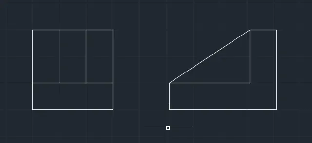
STEP 3
- Command: L LINE
- Specify first point:
- Specify next point 1.5 and press enter.
- Specify next point 2.0 and press enter.
- Specify next point 1.5 and press enter.
- Specify next point press esc to Cancel.
- Specify offset distance 0.5 and press enter.
- Select object to offset and press enter.
- Specify point on side to offset.
- type tr trim the oject not necessary and press enter.
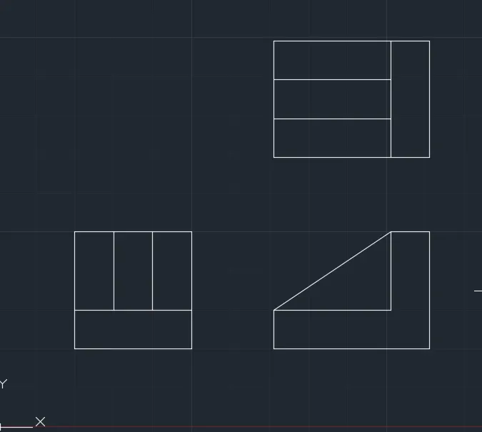
RESULT ; The following figure is done as per dimension is completed.
7)
AIM
TO draw the following figure using autocad.
INTRODUCTION
This drawing is created using autocad and the procedure is explained in detail in each steps and the commands are used in this drawing are.
COMMANDS USED
- L- LINE
- F8- ORTHO MODE
- GRIDMODE
- F10 - POLAR TRACKING
- C- CIRCLE
- M-MOVE
- RO-ROTATE
- TR-TRIM
- O-OFFSET
- F-FILLET
PROCEDURE
- open autocad file in windows desktop.
- a dialog box will open it shows startup from scratch.
- click the radio button imperial to start the project.
- in command box type gridmode to show the gridmode by typing 1 in the command box
- press F8 to get ortho on
- Type units press decimal to change the units.
STEP 1
COMMAND - L- LINE
- Specify first point:
- Specify next point 100 and press enter.
- Specify next point 210 and press enter.
- specify the next point 75 and press enter.
Command: F - FILLET
- Select first object or [Undo/Polyline/Radius/Trim/Multiple]: r
- Specify fillet radius <0.0000>: 15
- Select second object or shift-select to apply corner or [Radius]: 15
Command:CIRCLE
- Specify radius of circle or Diameter: 50 and press enter.
Command :A - ARC
- Specify start point of arc or [Center]:
- Specify second point of arc or [Center/End]: _c
- Specify center point of arc:end point
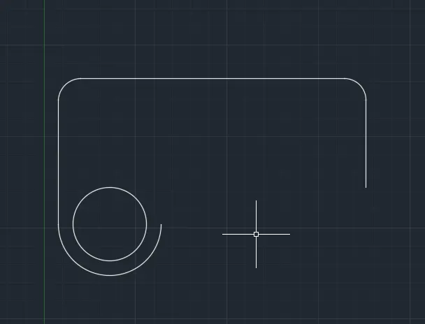
STEP 2
COMMAND -L-LINE
- Specify first point: 60 and press enter.
COMMAND -F- FILLET
- Select first object or [Undo/Polyline/Radius/Trim/Multiple]: R
- Specify fillet radius: 20 and press enter.
- Select first object or [Undo/Polyline/Radius/Trim/Multiple]: R
- Specify fillet radius : 6 and press enter.
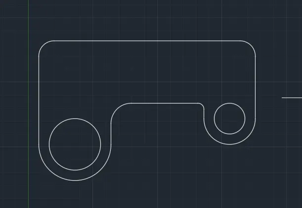
STEP 3
Command: -L -LINE
- Specify first point:
- Specify next point 20 and press enter.
- Specify next point 10 and press enter.
- Specify next point 70 and press enter.
- Specify next point 30 and press enter.
- Specify next point 70 and press enter.
- Specify next point c to close the line
COMMAND -CO- COPY
- Specify the first point and select the object
- specify the base point of the oblect and press enter.
- specify the next point 100 to copy the object and press enter.

RESULT : The following object is done as per dimension is completed.
8)
AIM
TO draw the following figure using autocad.
INTRODUCTION
This drawing is created using autocad and the procedure is explained in detail in each steps and the commands are used in this drawing are.
COMMANDS USED
- L- LINE
- F8- ORTHO MODE
- GRIDMODE
- F10 - POLAR TRACKING
- C- CIRCLE
- M-MOVE
- RO-ROTATE
- TR-TRIM
- O-OFFSET
- F-FILLET
- MI-MIRROR
PROCEDURE
- open autocad file in windows desktop.
- a dialog box will open it shows startup from scratch.
- click the radio button imperial to start the project.
- in command box type gridmode to show the gridmode by typing 1 in the command box
- press F8 to get ortho on
- Type units press decimal to change the units.
STEP 1
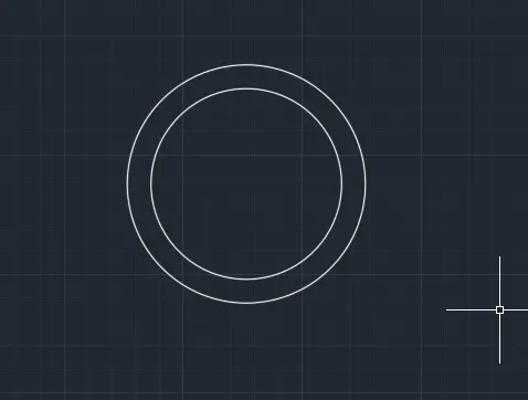
Command: C-CIRCLE
- Specify center point for circle and press enter.
- Specify radius of circle or Diameter: D and press enter.
- Specify diameter of circle 4 and press enter
- Specify diameter of circle 5 and press enter.
STEP 2
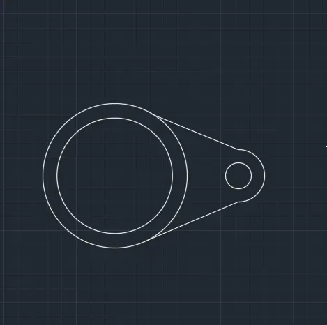
Command: -L-LINE
- Specify first point: 4.275
Command: -C-CIRCLE
- Specify radius of circle or Diameter; D and press enter.
- Specify diameter of circle 0.9 and press enter.
COMMAND - A- ARC
- Specify the first point as center,start,end
- specify next point as 0.9 the arc is completed.
STEP 3
COMMAND - MI-MIRROR
- Select the object to mirror to the opposite side.
- specify the base point of the object to mirror the option to the opposite side.
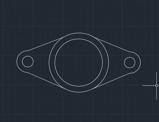
RESULT: THE following figure is done as per dimension is completed.
9)
AIM
TO draw the following figure using autocad.
INTRODUCTION
This drawing is created using autocad and the procedure is explained in detail in each steps and the commands are used in this drawing are.
COMMANDS USED
- L- LINE
- F8- ORTHO MODE
- GRIDMODE
- F10 - POLAR TRACKING
- C- CIRCLE
- M-MOVE
- RO-ROTATE
- TR-TRIM
PROCEDURE
- open autocad file in windows desktop.
- a dialog box will open it shows startup from scratch.
- click the radio button imperial to start the project.
- in command box type gridmode to show the gridmode by typing 1 in the command box
- press F8 to get ortho on
- Type units press engineering to change the units.
STEP 1
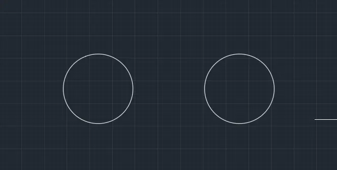
COMMAND - C -CIRCLE
- specify first point of the circle and set radius as 8' and press enter.
- type - L-line from the circle distance as 32'6'' and press enter.
- at the end of the line draw a circle.
- type c-circle specify next circle of the drawing at a radius 9' and press enter.
- type -E-erase the line at the center and press esc.
STEP 2
- COMMAND - C- CIRCLE or in home scroll down and pick tan,tan,radius.
- specify the first tangent point of the at the corner of the circle and press enter.
- specify the next point tangent point at the second circle and press enter.
- specify the radius of the circle 41'8'' and press enter.
- A full circle will appear type - tr -trim the circle which is not needed and press enter.
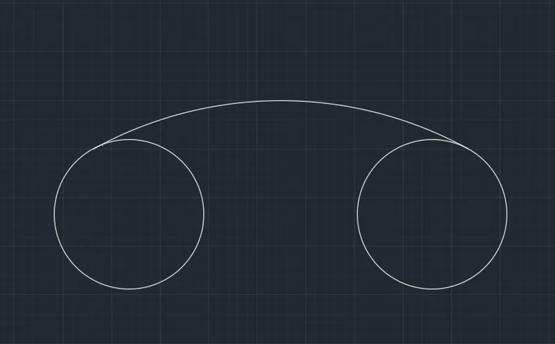
STEP 3
- specify the first tangent point of the at the corner of the circle and press enter.
- specify the next point tangent point at the second circle and press enter.
- specify the radius of the circle 41'8'' and press enter.
- A full circle will appear type - tr -trim the circle which is not needed and press enter.
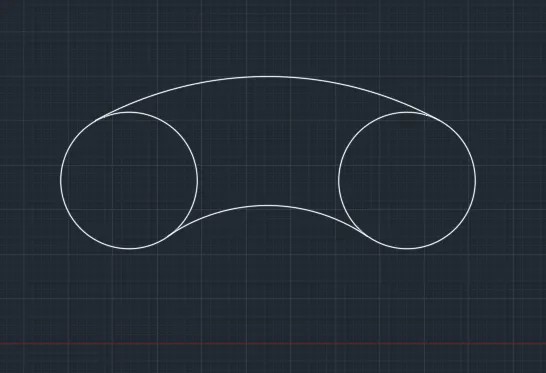
RESULT: THE following figure is done as per dimension is completed.
10)
AIM
TO draw the following figure using autocad.
INTRODUCTION
This drawing is created using autocad and the procedure is explained in detail in each steps and the commands are used in this drawing are.
COMMANDS USED
- L- LINE
- F8- ORTHO MODE
- GRIDMODE
- F10 - POLAR TRACKING
- C- CIRCLE
- M-MOVE
- RO-ROTATE
- TR-TRIM
- O-OFFSET
PROCEDURE
- open autocad file in windows desktop.
- a dialog box will open it shows startup from scratch.
- click the radio button imperial to start the project.
- in command box type gridmode to show the gridmode by typing 1 in the command box
- press F8 to get ortho on
- Type units press decimal to change the units.
STEP 1
COMMAND - REC- RECTANGLE
- Specify the first point 1,1 and press enter.
- specify the next point 4,4 and press enter. sqaure is formed
- type offset distance as 1 and press enter.
- two set of squares are formed.
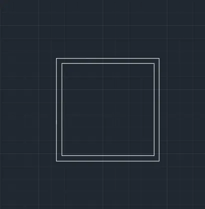
STEP 2
- TYPE rectangle in a free space
- type rotate to rotate the angle at 45degree
- command- m-move the object to the centre of the rectangle.
- command tr- trim
- trim the object which is not necessary as per shown drawing .
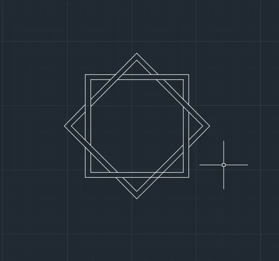
RESULT: THE following figure is done as per dimension is completed.
11)
AIM
TO draw the following figure using autocad.
INTRODUCTION
This drawing is created using autocad and the procedure is explained in detail in each steps and the commands are used in this drawing are.
COMMANDS USED
- L- LINE
- F8- ORTHO MODE
- GRIDMODE
- F10 - POLAR TRACKING
- C- CIRCLE
- M-MOVE
- RO-ROTATE
- TR-TRIM
- O-OFFSET
PROCEDURE
- open autocad file in windows desktop.
- a dialog box will open it shows startup from scratch.
- click the radio button imperial to start the project.
- in command box type gridmode to show the gridmode by typing 1 in the command box.
- press F8 to get ortho on.
- Type units press engineering to change the units.
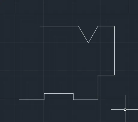
STEP 1
COMMAND - L- LINE
- Specify the first line as 4'6'' and press enter.
- specify the next point 3' and press enter.
- specify the next point 9' in vertical direction and press enter.
- press f8 to ortho off to set and angle of 30 degree and press enter.
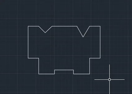
STEP 2
- TYPE L- LINE draw a horizontal distance. and press enter.
- press f8 to ortho off and set an angle of 45 degree and press enter.
- specify the next point 13'6'' in the vertical direction and press enter.
- specfy the next point 3' in the horizontal direction and press enter.
- press c to close the drawing.
STEP 3
TYPE REC- RECTANGLE
- specify the point 3',3' and press enter.
type RO- ROTATE
- rotate the square at a 45 degree and press enter.
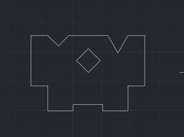
RESULT: THE following figure is done as per dimension is completed.