Creating a Floor plan, Footing detail and Isometric view using AutoCad
C1 ) LOAD BEARING WALL OVER SPREAD FOOTING
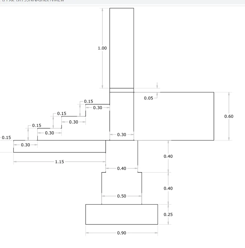
AIM
- TO draw the following figure using autocad
INTRODUCTION
The desired cross section of a load bearing wall over spread footing is created in autocad using xy plane and the procedure of drawing is explained in detail with diagram
PROCEDURE
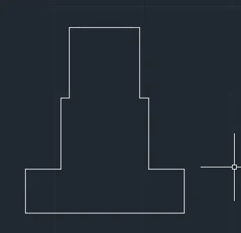
STEP 1
- open autocad file in windows desktop.
- a dialog box will open it shows startup from scratch.
- click the radio button imperial to start the project.
- in command box type gridmode to show the gridmode by typing 1 in the command box
- press F8 to get ortho on
- TYPE L in command box for LINE
- specify first point 1,1 in the command prompt
- specify the next point in x axis 0.9 and press enter and it shows the straight line.
- specify the next point y axis 0.25 and press enter.
- and specify the next point 0.2 in x axis and press enter
- and next point 0.4 and press enter.
- next point 0.05 in x axis and press enter.
- next point 0.40 in y axis and press enter
- next point 0.05 in x axis and press enter.
- same procedure continues in opposite side
- and press esc to close the footing.
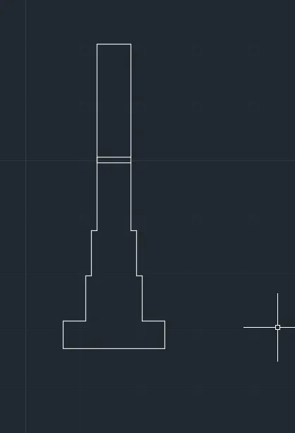
STEP 2
- type L in the command box
- specify the last point from that point in y axis 1.65 and press enter
- specify the next point x axis in 0.30.
- specify the next point 1 in y axis.
- specify the next point in x axis 0.30
- and press esc to close.
- the figure is shown.
STEP 3
- for the stairs type L in the command box.
- point 0.15 in y axis.
- specify the next point in x axis 0.30
- specify the next point in y axis 0.15
- continously until the stairs are done.
- PRESS ESC to close.
COMMANDS USED
- STARTUP
- L- LINE
- GRIDMODE- GRIDMODE
- F8 - ORTHO MODE ON
- O- OFFSET
- T - TEXT
- E - ERASE
- U - UNDO
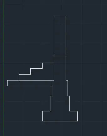
RESULT :the given above diagram of load bearing wall over spread footing is completed.
C2) ISOLATED FOOTING
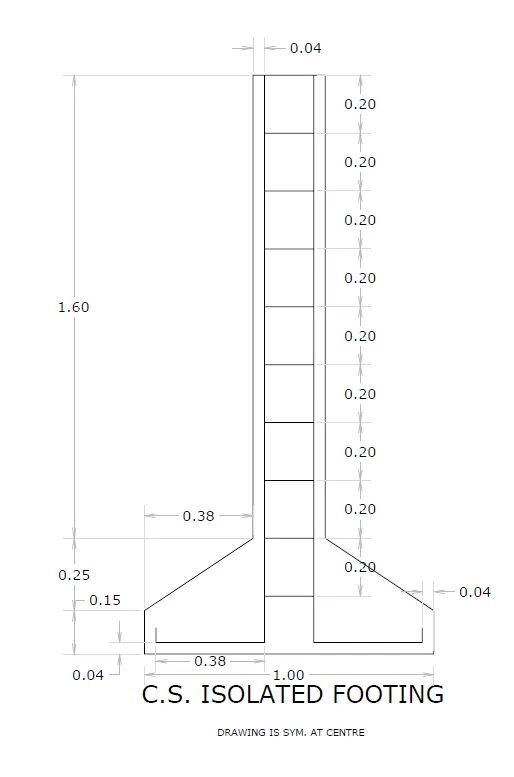
AIM
to draw the following figure using autocad.
INTRODUCTION
The desired cross section of a isolated footing is created in autocad using xy plane and the procedure of drawing is explained in detail with diagram.
PROCEDURE
STEP 1
- Type startup to start a new drawing
- type L command in the command box.
- type 1,1 to start from corner of the XY plane.
- click the radio button imperial to start the project.
- in command box type gridmode to show the gridmode by typing 1 in the command box
- press F8 to get ortho on
- type CHA FOR chamfer command to do the diagnol part press d for distance and type d1 and d2 to do the diagnol part of the footing.
- type O for OFFSET cmd to copy the line.
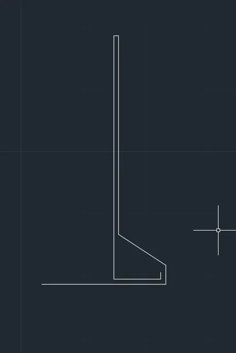
STEP 2
- type L for LINE in command box.
- start from the corner of the point
- make the same specific point in the opposite direction.
- type O in command box for OFFSET specify the distance and press enter
- press E to ERASE the object which is not necessary.
COMMANDS USED
- STARTUP
- L- LINE
- GRIDMODE- GRIDMODE
- F8 - ORTHO MODE ON
- O- OFFSET
- CHA - CHAMFER
- PL - POLYLINE
- T - TEXT
- E - ERASE
- U - UNDO
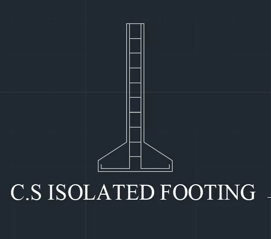
RESULT : THE given following isolated footing is done as per dimension is completed.
C3) LINE DRAWING OF A ONE BEDROOM BUILDING
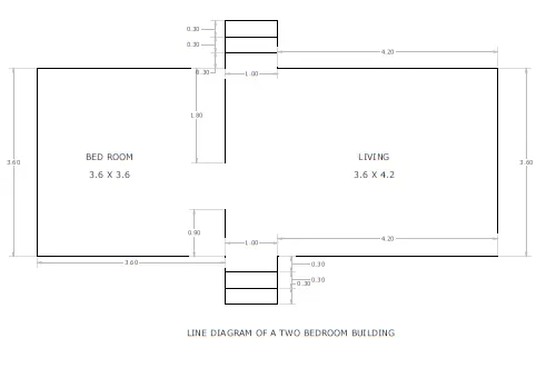
AIM
to draw the following figure using autocad.
INTRODUCTION
The plan of a line diagram of a one bedroom is created in autocad using xy plane and the procedure of drawing is explained in detail with diagram.
PROCEDURE
- Type startup to start a new drawing
- click the radio button imperial to start the project.
- in command box type gridmode to show the gridmode by typing 1 in the command box
- press F8 to get ortho on.
- type PL FOR POLYLINE command in the command box.
- type 1,1 to start from corner of the XY plane.
COMMANDS USED
- STARTUP
- L- LINE
- GRIDMODE- GRIDMODE
- F8 - ORTHO MODE ON
- O- OFFSET
- CHA - CHAMFER
- PL - POLYLINE
- T - TEXT
- E - ERASE
- U - UNDO
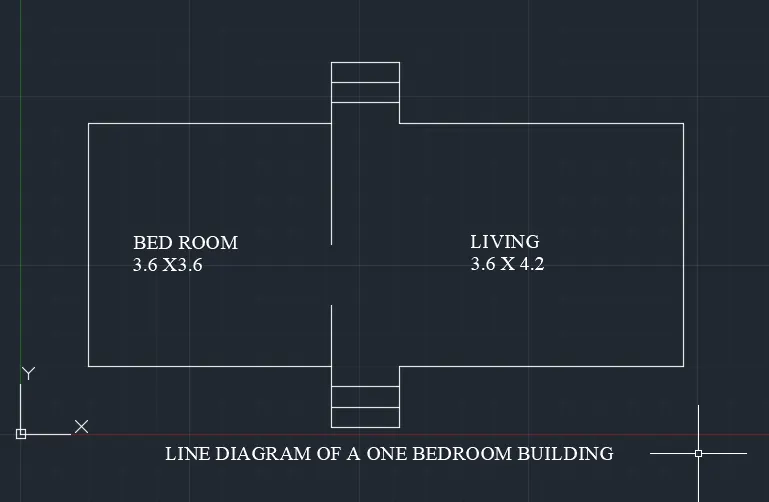
RESULT: THE given following line drawing of a one bedroom is done as per dimension is completed.
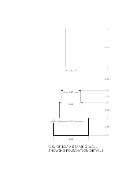
C4) C.S LOAD BEARING WALL
AIM
- to draw the following figure using autocad.
INTRODUCTION
The desired cross section of a load bearing wall shqwing foundation details is created in autocad using xy plane and the procedure of drawing is explained in detail with diagram.
PROCEDURE
- Type startup to start a new drawing
- click the radio button imperial to start the project.
- in command box type gridmode to show the gridmode by typing 1 in the command box
- press F8 to get ortho on.
- type PL FOR POLYLINE command in the command box.
- type 1,1 to start from corner of the XY plane.
STEP 1
I USED POLYLINE IN THIS DRAWING.
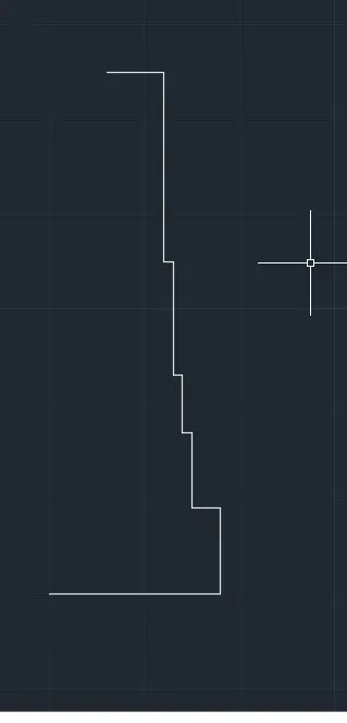
step 2
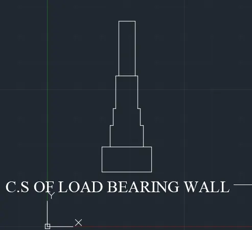
COMMAND USED IN THIS DRAWING
- STARTUP
- PL - POLYLINE
- GRIDMODE- GRIDMODE
- F8 - ORTHO MODE ON
- O- OFFSET
- T - TEXT
- E - ERASE
- U - UNDO
RESULT : the given C.S of a load bearing wall showing foundation details is done as per dimension is completed using autocad.
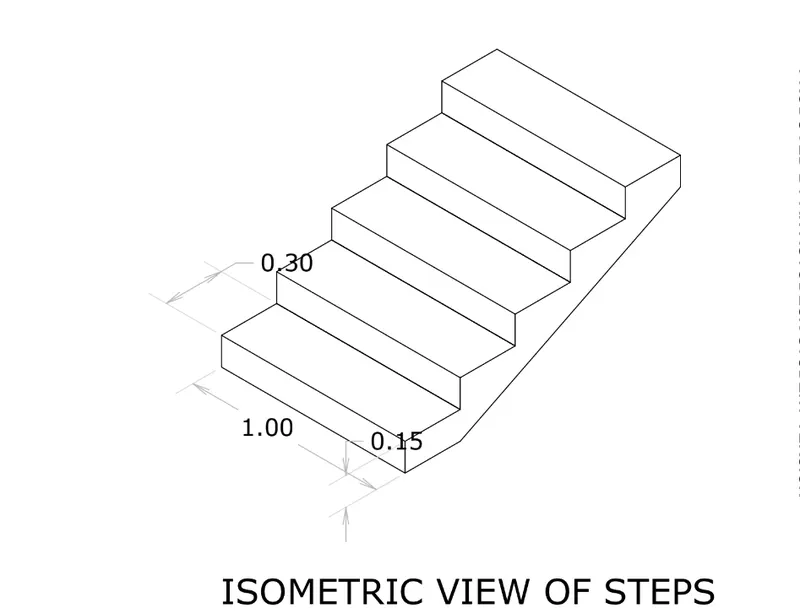
C5) ISOMETRIC VIEW OF STEPS
AIM
- to draw the following figure using autocad.
INTRODUCTION
The desired cross section of a isometric views of steps is created in autocad using xyz plane and the procedure of drawing is explained in detail with diagram.
PROCEDURE
- Type startup to start a new drawing
- click the radio button imperial to start the project.
- in command box type gridmode to show the gridmode by typing 1 in the command box
- press F8 to get ortho on.
- press view cube icon to change the view to isometric xyz plane
- type L- LINE command in the command box.
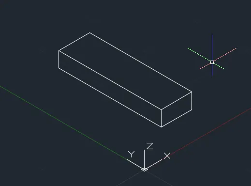
STEP 1
- start from a specific point.
- type L in command box draw 1.00 in y axis plane
- specify 2nd point 0.15 in z axis.
- specify the 3rd point 0.30 in x axis.
- specify the 4th point 1.00 in y axis.
- specify the 5th point 0.30 in x axis.
- specify the 6th point 0.15n in zaxis.
- the first step is created.
STEP 2
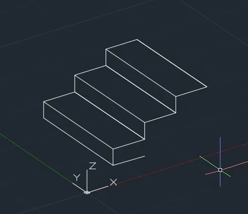
STEP 3
COMMAND USED IN THIS DRAWING
- STARTUP
- GRIDMODE- GRIDMODE
- F8 - ORTHO MODE ON
- L - LINE
- F5 - to toggle the isometric view to right, left, top
- T - TEXT
- E - ERASE
- U - UNDO
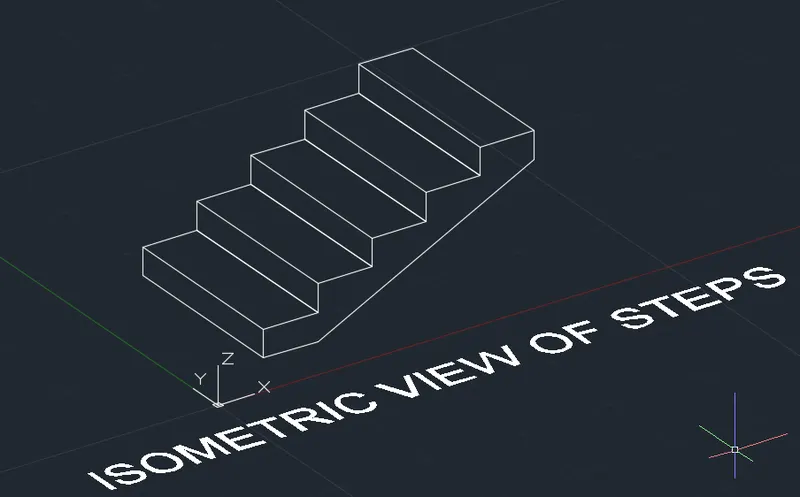
RESULT :the given isometric view of steps is done as per dimension is completed.
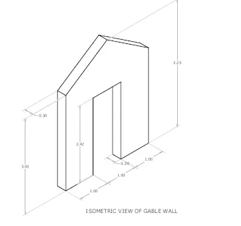
C6) ISOMETRIC VIEW OF GABLE WALL
AIM
- to draw the following figure using autocad.
INTRODUCTION
The desired cross section of a isometric views of gable wall is created in autocad using xyz plane and the procedure of drawing is explained in detail with diagram.
PROCEDURE
- Type startup to start a new drawing
- click the radio button imperial to start the project.
- in command box type gridmode to show the gridmode by typing 1 in the command box
- press F8 to get ortho on.
- press view cube icon to change the view to isometric xyz plane
- type L- LINE command in the command box.
STEP 1
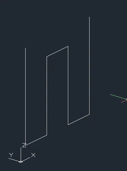
STEP 2
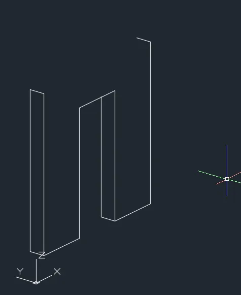
STEP 3
COMMAND USED IN THIS DRAWING
- STARTUP
- GRIDMODE- GRIDMODE
- F8 - ORTHO MODE ON
- L - LINE
- F5 - to toggle the isometric view to right, left, top
- CHA - CHAMFER
- T - TEXT
- E - ERASE
- U - UNDO
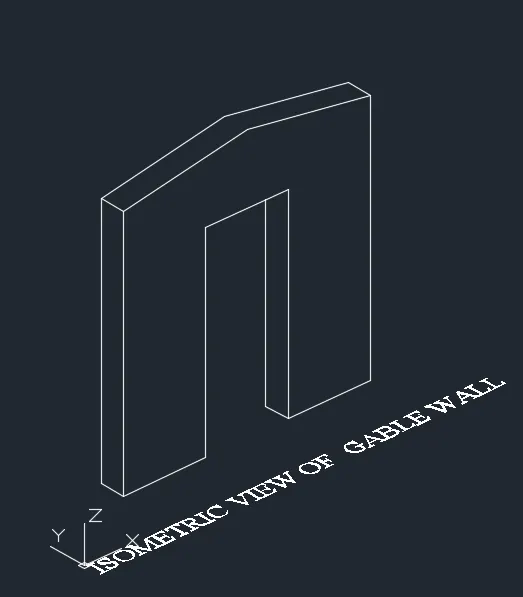
RESULT : The given isometric view of gable wall is done as per dimension completed.