Creating a Residence Layout, Seating plan, Toilet and Utility room plan using AutoCad
CHALLENGE 1
To draw the following plan using autocad.
INTRODUCTION
This plan is created using autocad and the procedure is explained in detail in each steps and the commands are used in this drawing are.
COMMANDS USED IN THIS DRAWING
- L- LINE
- F8- ORTHO MODE
- GRIDMODE
- F10 - POLAR TRACKING
- C- CIRCLE
- X- XLINE
- CO-COPY
- M-MOVE
- T- TEXT
- TR- TRIM
- O-OFFSET
- F- FILLET
- D-DIMENSION STYLE
- REC-RECTANGLE
PROCEDURE
- open autocad file in windows desktop.
- a dialog box will open it shows startup from scratch.
- click the radio button imperial to start the project.
- in command box type gridmode to show the gridmode by typing 1 in the command box
- type F8 to get ortho on.
- type limmax to set the maximum layout.
- type llmits to set the layout.
- TYPE UN FOR UNITS and set to engineering , feet and inches.
STEP 1
TYPE XL - XLINE
- Specify the point in the x axis and y axis.
TYPE L - LINE
- specify the first point 43'6.5'' in the y axis and press enter.
- specify the next point 25' in the x axis and press enter.
TYPE O -OFFSET
- Specify the point through 43'6.5 for the wall thickness 9'' for the wall thickness in the y axis and press enter.
- Specify the point through 25' for the wall thickness of 9'' in the x axis and press enter.
- specify the next point 6' in the y axis and press enter.
- specify the next point 9'' in the y axis and press enter.
- specify the next point 6'8'' in the y axis and press enter.
- specify the next point from 6'9'' in the y axis offset of 18'0.5'' and press enter.
- specify the next point 4.5'' for the inner wall and press enter.
- from 4'6'' in the y axis and press enter.
- for the wall of 4.5'' and press enter.
- from the 4.5 ''inch wall type 12' and press enter.
- all in the y axis division is divided
- in the x axis wall offset of 9'' wall and press enter
- from the wall axis 11'7.5 in the axis and press enter
- and 4.5'' for the subdivision of wall and press enter.
- from the wall 11'6'' take o offset and press enter.
- from 9'' and press enter.
- all in the x axis are completed.
STAIRS PORTION
- draw a line of 6' and press enter.
TYPE O - OFFSET
PRESS COMMAND TR- TRIM
- Trim the portion according to the plan.
- for the door and wall portion and window.
TYPE C - CIRCLE
- FOR the door portion draw the circle and trim the portion which is not needed.
- as per dimension the plan is created
- the door portion is completed.
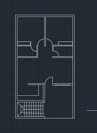
STEP 2
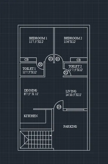
TYPE -T -TEXT
- Specify the first point for the text to be created.
- type the text as per rooms and press enter.
COMMAND CO-COPY
- copy the text according to the room.
- press the text to edit to the room wise.
STEP 3
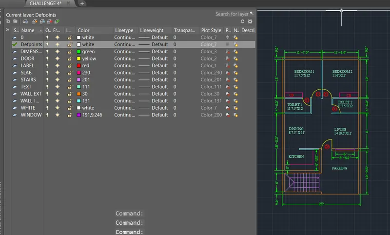
ADDING LAYERS
- press layer properties.
- press new layer to create the layer.
- create layers for outer wall, inner wall, text, dimension, stairs,slabs, door window and labelling.
STEP 4
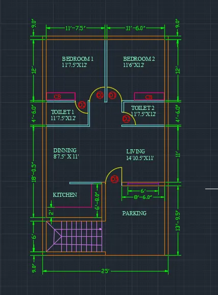
RESULT : The following plan is done as per dimension is completed.
CHALLENGE 2
AIM
To draw the following plan using autocad.
INTRODUCTION
This plan is created using autocad and the procedure is explained in detail in each steps and the commands are used in this drawing are.
COMMANDS USED IN THIS DRAWING
- L- LINE
- F8- ORTHO MODE
- GRIDMODE
- F10 - POLAR TRACKING
- C- CIRCLE
- CO-COPY
- M-MOVE
- T- TEXT
- TR- TRIM
- A - ARC
- O-OFFSET
- D-DIMENSION STYLE
- REC-RECTANGLE
- MI-MIRROR
PROCEDURE
- open autocad file in windows desktop.
- a dialog box will open it shows startup from scratch.
- click the radio button imperial to start the project.
- in command box type gridmode to show the gridmode by typing 1 in the command box
- type F8 to get ortho on.
- type limmax to set the maximum layout.
- type llmits to set the layout.
- TYPE UN FOR UNITS and set to decimal , millimeter.
STEP 1
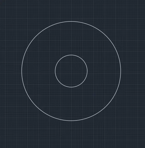
TYPE C - CIRCLE
- Specify the centre point for the circle
- set the radius of outer circle of 1398 and press enter.
- set the inner circle of radius of 452 and press enter.
STEP 2
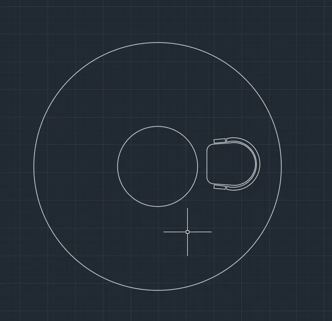
for the seating
type L - line
- for a specific distance line is carried out.
TYPE F -FILLET
- FILLET are used for corners of radius of the seating set a radius and press enter.
TYPE - REC - RECTANGLE
- Rectangle is used to hand rest position for a specific distance is carried out.
PRESS A - ARC
- press tan tan tan to curve the seating.
- the arc is used for the curve distance of the seating.
TYPE O - OFFSET
- offset the distance of the arc is carried out for the specific distance.
STEP 3
STEP 4
TYPE MI - MIRROR
- press mirror to the object of the seating and press enter.
- press to centre of the radius of the circle and press enter.
- press no the object will be mirrored to the opposite side.
TYPE CO -COPY
- COPY the object the seating to the top of the inner circle.
TYPE -RO -ROTATE
- rotate the object to the 90 degree and press enter.
TYPE MI- MIRROR
- select the object to mirrored to the bottom and press no. to be copied.
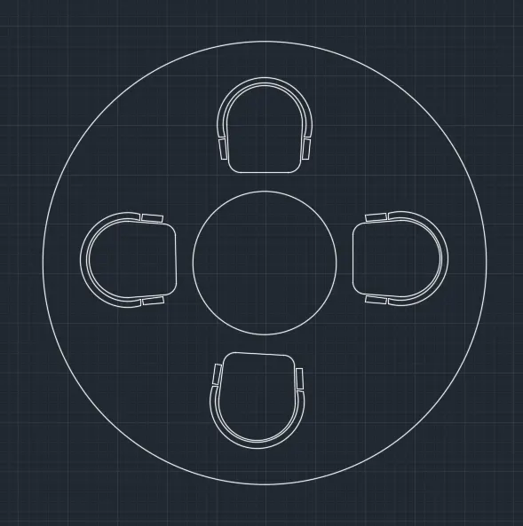
RESULT : The following figure is done as per dimension is completed.
CHALLENGE 3
AIM
To draw the following plan using autocad.
INTRODUCTION
This plan is created using autocad and the procedure is explained in detail in each steps and the commands are used in this drawing are.
COMMANDS USED IN THIS DRAWING
- L- LINE
- F8- ORTHO MODE
- GRIDMODE
- F10 - POLAR TRACKING
- X- XLINE
- C- CIRCLE
- CO-COPY
- M-MOVE
- T- TEXT
- TR- TRIM
- A - ARC
- O-OFFSET
- D-DIMENSION STYLE
- REC-RECTANGLE
- MI-MIRROR
- CHA - CHAMFER
PROCEDURE
- open autocad file in windows desktop.
- a dialog box will open it shows startup from scratch.
- click the radio button imperial to start the project.
- in command box type gridmode to show the gridmode by typing 1 in the command box
- type F8 to get ortho on.
- type limmax to set the maximum layout.
- type llmits to set the layout.
- TYPE UN FOR UNITS and set to decimal , millimeter.
STEP 1
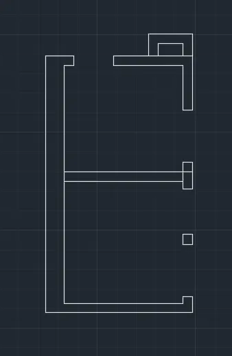
TYPE XL - XLINE
- Specify the point in the x axis and y axis.
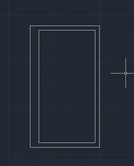
TYPE L - LINE
- specify the first point 2350 in the X axis and press enter.
- specify the next point 4250 in the Y axis and press enter.
TYPE O -OFFSET
- Specify the first point of offset wall thickness 300 mm in the x axis and press enter.
- specify the next point of 1900 mm in the x axis and press enter.
- speciy the next point of wall thickness 150 mm and press enter.
- specify the next point wall thickness of 300 in the y axis and press enter.
- specify the next point 1700 mm in the y axis and press enter.
- specify the next point 150 mm for the division inner and press enter.
- specify the next point 2100 mm for the division inner wall and press enter.
TYPE TR-TRIM
- specify distance of opening for window, door, ventilation as per dimension.
STEP 3
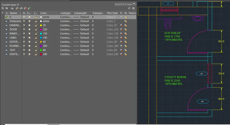
ADDING LAYERS
- press layer properties.
- press new layer to create the layer.
- create layers for outer wall, inner wall, text, dimension,door,window and labelling.
TYPE -T -TEXT
- specify the text as per room dimension and press enter.
TYPE C - CIRCLE
- Use the circle to draw the door.
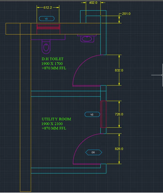
RESULT : The follwing plan is done as per dimension is completed.