Sketch a G+1 residential plan according to Vaastu Shastra and Calculation of Loads as per IS code
ANSWERS:
G+1 RESIDENTIAL BULIDING PLAN ACCORDING TO VAASTU SHASTRA:
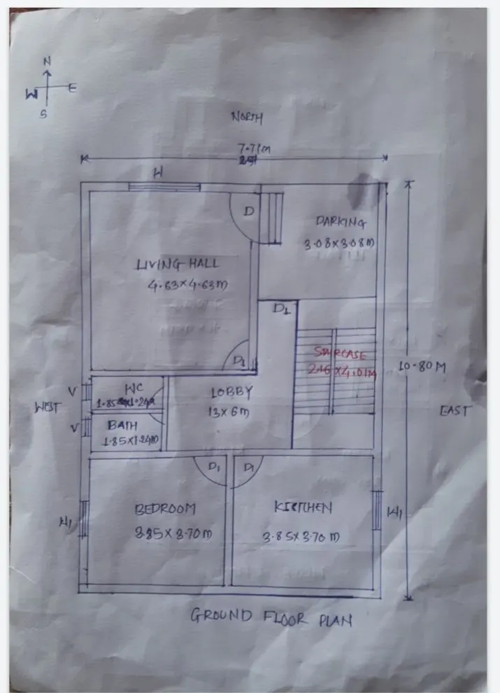
GROUND FLOOR
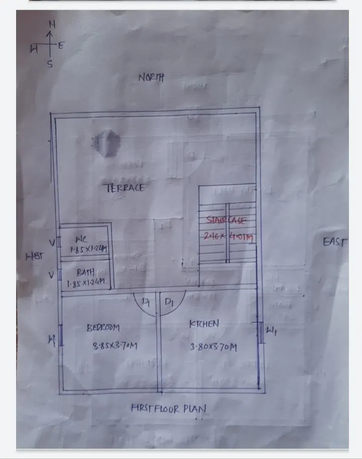
1ST FLOOR PLAN
Detailing of building elements:
Size of column: 300mm*300mm
Size of column: 300mm*450mm
Height of brick wall: 4.5m
Thickness of slab: 125mm
Thickness of brick wall: 230mm and 110 mm
Size of door (D): 1240mm*2100mm
Size of door (D1): 925mm*2100mm
Size of window(W): 1240mm*1240mm
Size of window(W1): 925mm*1240mm
Size of ventilator(V): 650mm*450mm
All other dimensions are provided in drawing.
STRUCTURAL DRAWINGS:
- Excavation or trench plan
- Footing and column layout with reinforcement
- Column schedule with reinforcement details
- Plinth beam layout with reinforcement details
- Floor to floor beam and slab layouts
- Liftpit and headroom reinforcement detail
Excavation or trench plan:
- On-site excavations or execution of Trenches for Sub-Structure of the building requires a plan where all the trenches are marked according to Grid of centreline markings and the offsets of dimensions respectively.
- Trench Plan highlights the dimensions (Length, Breadth, Depth) of trenches to be to excavated with reference to Centreline Grid.
- It is required at an early stage, immediately after marking Centreline on-Site.
Footing and column layout with reinforcement
Column schedule with reinforcement details
Plinth beam layout with reinforcement details
- It is used for marking the Tie beam (Primary element for ‘Earthquake Resistant Structure’) which is used for connecting the columns emerging from the Sub-Structure (structure beneath the ground level) of the building.
- This layout gives the orientation of the Tie Beam to the column and also the Cross-section sizes with specifications of the design.
Floor to floor beam and slab layouts
- It includes the layout of roof slabs concerning the corresponding beam by the Centreline Grid Markings of Columns-Beams.
- This involves the orientation of the roof slab and Reinforcement Bar Details to be incorporated according to Structural Design.
- Details like diameter and number of reinforcement bars in a defined length are mentioned in roof slab layout for structural stability.
Liftpit and headroom reinforcement details
- The reinforcement details for liftpit and headroom is given separately.
CALCULATION OF LOAD FOR INDIVIDUAL ELEMENT OF BUILDING ACCORDING TO IS CODE:
Dead load calculation:
Assume, unit weight of rcc column, beam and slab = 25 KN/m3
Unit weight of brick wall = 20 KN/m3
For column:
Height of column is 4.5m.
C/s given as = 300*300mm
Unit weight of RCC column = 25 KN/m3
Total weight of concrete = 4.5*0.3*0.3
= 0.405 m3
Self weight of column = 0.405* unit weight of column
= 0.405*25
= 10.125 KN
Total load due to column = no. of column* self weight of column
For beam:
c/s given as = 300*450mm
Unit weight of RCC beam = 25 KN/m3
Total weight of concrete = 0.3*0.45
= 0.135
Self weight of beam = 0.135* unit weight of beam
= 0.135*25
= 3.375 KN/m
For slab:
Thickness of slab = 125mm
Load of slab for 1m2 area = 0.125*Unit weight
= 0.125*25
= 3.125 KN/m3
For wall:
Height of wall = 4.5m
Suppose thickness of wall = 230mm, 110 mm
For brick thickness = 230mm
Load due to brick wall per unit length = unit weight of brick wall* volume of brick wall
= 20*0.230*4.5*1
= 20.7 KN/m
For brick thickness = 110mm
Load due to brick wall per unit length = unit weight of brick wall* volume of brick wall
= 20*0.110*4.5*1
= 9.9 KN/m