Sketch a G+1 residential plan according to Vaastu Shastra and Calculation of Loads as per IS code
AIM: To drow a plan of G+1 residential according to Vaastu Shastra, and list down the names of the structural drawings required to be provided to the site for construction.
INTRODUCTION:
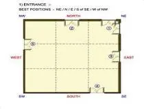
- Shape: The rooms of your house should preferably be square or rectangular.
- Room Basics: Rooms should be airy, well lit, bright, and clean. ...
- Home Centre: The centre of the house should be an empty space.
- Stairs and Furniture: ...
- Water: ...
- Dining Table: ...
- Mirror Placement:
Types of Construction drawings use regularly in construction industries.
1. Block Plan
This drawing gives a layout of the site or the buildings in the surrounding area, laid out on a map drawn to scale.
- It gives a firsthand idea of the roads, boundaries and other such details that are necessary to understand where your construction site lies.
- It helps the person dealing with your construction plan or project request to understand what and where you are proposing it and help you out with it too.
- Block plans are made in relation to Ordnance Survey Maps and the recommended scales used are 1:2500, 1:1250 or 1:500.
2. Architectural Drawings
Architectural Drawings are drawing work that is used in building drawings to depict the dimensions, depth, and layout of the actual building, prior to beginning the construction. Architectural Drawings act as a blueprint construction, drawn to scale, to help the engineers visualize the project.
Various types of Architectural Drawings commonly used are:
- Foundation plan – not to be mistaken for just the ground or basement floor plan. Foundation Plans are drawing work to render any of the floors of the building being constructed. They help visualize the dimension, size, shape, height and configuration of rooms/stairs/landings with each other.
- Floor plans – in-depth rendering of the layout of the rooms for each floor. It describes in 2D the orientation of rooms and components to each other. Floor plans may or may not be utilized in commercial or non-commercial building projects, but it is necessarily still made as part of the drawing work.
- Sectional Drawings – these are drawings that depict a part or whole of the framework in sliced form. It helps understand the measurements of various building components with each other, the materials used in the construction of those components, the height, depth, and hollowness, etc.
- Elevation Drawings – these architectural drawings offer an aesthetic overview of the various components of the building such as columns, windows, and doorframes. It also helps understand the relative surface, internal markings, and relative height of these different components to each other.
3. Production Drawings
These Construction Drawings are used to convey functional information to the workers and engineers on site. It describes the materials, the assembly of various parts, the tools required, the dimensions, and other information required during the process. It may also include additional information or an infographic on how to meet those set requirements.
4. Structural Drawings
Structural Drawings also serve as civil engineering drawings. They are useful in understanding the physical nitty-gritty of a building framework. They act as a structural design guide for the workers and on-site engineers. Common types of structural drawings are:
- General Note – an overview of all the codes, procedures, and abbreviations, etc required to give a comprehensive guide to getting to work on the construction site. This includes concrete mix, details for other structural drawings, lengths and construction types of each component, etc.
- Excavation Drawing – this civil engineering drawing describes the dimensions and positions for the excavation process prior to the actual building work. It covers details like tunneling, shafts, removal of soil, grid plans, etc required to start the groundwork.
- Column Layouts – These structural drawings include the layouts of the way columns will be laid out. It makes it easier for contractors to plan the layout of the building and start the process by identifying the position and distance between columns across the floor.
- Beam Layouts – It includes all the beam-like structures, such as the ones supporting the roof and the windows, or the beams used for strengthening purposes. They are designed for each floor and cover the length, height, material, etc.
- Roof slab layouts – this civil engineering drawing describes the exact dimensions of all the slabs required for roofs or slants. It can be designed over AutoCAD software as it requires precision and data.
5. Electrical drawings
Most residential construction drawings or commercial construction drawings require a functional outline of the number of power outlets, light fixtures, fan fixtures, etc. They also include the wiring pattern and details about the electrical load it can carry. Common details included in Electrical Drawings are:
- Earthing layout
- Light fixture layout
- Generator and other equipment
- Cable tray layout
- Hazardous area classifications
- Lighting protection system
6. Plumbing Drawings
Just like electrical layouts, plumbing is another part of any residential or commercial construction drawing that marks the points where plumbing components need to be set up. Space is left here accordingly for further pipe and sanitary ware fixtures to be added once the structural component is finished. Plumbing drawings commonly include:
- Pipes –water pipes, drainage pipes, internal pipes
- Material of pipes
- Outlet points – taps, sinks, tanks etc
- Position and location of pipes and outlets
7. HVAC Drawings
These are known as mechanical construction drawings. They provide details and a design framework for heating and ventilation systems in a building. Central heating/cooling, air conditioning vents, ventilators, etc are all included according to the need and site of the building plans. Builders use these design constructs in their process accordingly.
8. Firefighting Drawings
In today’s construction systems, safety design is paramount. Firefight Drawings are also a part of blueprint drawings of a building that allocate points for fire hoses, fire escapes, water outlets, sandbags, or any other fire safety equipment required by the regulatory body overseeing the project.
9. Environmental Plans
Making sure environmental guidelines and management is properly followed is a part of construction projects that cannot be overlooked. The aim is to minimize environmental damage and future negative impacts of the construction project. It includes measures like:
- Chemical disposal mechanisms
- Management of erosion and sedimentation
- Outlining environmental guideline compliance measures
- Measures to handle accidents and emergencies like fire
10. Finishing Drawings
These include finer and more detailed plans of the building after the whole structural and architectural framework has been set up. These are required for the aesthetic and functional value of the building. These construction drawings include details of:
- Tile patterns,
- Floor patterns
- False ceilings
- Paint colors and textures
- Plaster
- Woodwork
- Motifs and designs
-
Different Load Calculation on Column, Beam, Wall & Slab
- Column = Self Weight x Number of floors
- Beams = Self Weight per running meter
- Wall Load Per Running Meter
- Total Load on Slab (Dead Load + Live Load +Wind Load + Self-Weight)
Besides this above loading, the columns are also subjected to bending moments that have to be considered in the final design. These tools are reduced laborious and consuming method of manual calculations for structural design, this is highly recommended nowadays in the field.
-
While doing calculations, we assume the self weight of columns is between 10 to 12 kN per floor.
Beam Load Calculation:
We adopt the same method of calculations for beam also.
we assume each meter of the beam has dimensions of 300 mm x 600 mm excluding slab thickness.
Assume each (1m) meter of the beam has dimension
Beam Load Calculation
- 300 mm x 600 mm excluding slab.
- Volume of Concrete = 0.30 x 0.60 x 1 =0.18 m³
- Weight of Concrete = 0.18 x 2400 = 432 kg
- Weight of Steel (2%) in Concrete = 0.18 x 2% x 7850 = 28.26 kg
- Total Weight of Column = 432 + 28.26 = 460.26 kg/m = 4.51 KN/m
So, the self-weight will be around 4.51 kN per running meter.
we know that the Density of bricks varies between 1800 to 2000 kg/m3.
For a 9 inch (230 mm) thick Brick wall of 2.55-meter height and a length of 1 meter,
The load / running meter to be equal to 0.230 x 1 x 2.55 x 2000 = 1173 kg/meter,
which is equivalent to 11.50 kN/meter.
This method can be adopted for load calculations of Brick per running meter for any brick type using this technique.
For aerated concrete blocks and auto-claved concrete (ACC) blocks, like Aerocon or Siporex, the weight per cubic meter is between 550 to 650 kg per cubic meter.
The load/running meter to be equal to 0.230 x 1 x 2.55 x 650= 381.23 kg
if you are using these blocks for construction, the wall loads per running meter can be as low as 3.74 kN/meter, use of this block can significantly reduce the cost of the project.
Slab Load Calculation:
Let, Assume the slab has a thickness of 150 mm.
So, the Self-weight of each square meter of the slab would be
Slab Load Calculation = 0.150 x 1 x 2400 = 360 kg which is equivalent to 3.53 kN.
Now, If we consider the Floor Finishing load to be 1 kN per meter, superimposed live load to be 2 kN per meter, and Wind Load as per Is 875 Near about 2 kN per meter.
So, from the above data, we can estimate the slab load to be around 8 to 9 kN per square meter.
load Calculation Column Beam Wall Slab
Load Calculation on Column:
- Volume of Concrete = 0.23 x 0.60 x 3 =0.414m³
- Weight of Concrete = 0.414 x 2400 = 993.6 kg
- Weight of Steel (1%) in Concrete = 0.414x 0.01 x 8000 = 33 kg
- Total Weight of Column = 994 + 33 = 1026 kg = 10KN
Wall Load Calculation
- Density of brick wall with mortar is about ranging between 1600-2200 kg/m3. So we consider self weight of brick wall is 2200 kg/m3 in this calculation.
- Volume of brick wall: Volume of brickwall = l × b ×h, Length = 1 meter, Width = 0.152 mm, Height of wall = 2.5 meter, Volume = 1m× 0.152 m× 2.5 m, Volume of brick wall = 0.38 m3
- Dead load of brick wall: Weight = volume × density, Dead load = 0.38 m3 × 2200 kg/m3, Dead load = 836 kg/m
- It will be converted into kilo Newton by dividing with 100 we will get 8.36 kN/m
- So dead load of a brick wall is about 8.36 kN/m acting on column.
Beam Load Calculation
- 300 mm x 600 mm excluding slab thickness.
- Volume of Concrete = 0.30 x 0.60 x 1 =0.18 m³
- Weight of Concrete = 0.18 x 2400 = 432 kg
- Weight of Steel (2%) in Concrete = 0.18 x 2% x 7850 = 28.26 kg
- Total Weight of Column = 432 + 28.26 = 460.26 kg/m = 4.51 KN/m
Column Load
A column is an essential structural member of the RCC structure that helps transfer the superstructure’s load to the foundation. It is a vertical compression member subjected to direct axial load and its effective length is three times larger than its least lateral dimension.
Dead Load Calculation for a Building
Dead load = volume of member x unit weight of materials.By calculating the volume of each member and multiplying by the unit weight of the materials from which it is composed, an accurate dead load can be determined for each component.
Column Design Calculations
- Volume of Concrete = 0.23 x 0.60 x 3 =0.414m³
- Weight of Concrete = 0.414 x 2400 = 993.6 kg
- Weight of Steel (1%) in Concrete = 0.414x 0.01 x 8000 = 33 kg
- Total Weight of Column = 994 + 33 = 1026 kg = 10KN
Footing Load Calculations
For a 6″ thick wall with 3 meter height and 1 meter length, the load can be measured per running meter equivalent to 0.150 x 1 x 3 x 2000 = 900 kg which is equivalent to 9 kN/meter. The load per running meter can be measured for any brick type by following this method.
Concrete Slab Load Calculations
- Size of Slab Length 3 m x 2 m Thickness 0.150 m
- Concrete Volume = 3 x 2 x 0.15 =0.9 m³
- Concrete weight = 0.9 x 2400 = 2160 kg.
Steel Load Calculation
- Size of Slab Length 3 m x 2 m Thickness 0.150 m
- Concrete Volume = 3 x 2 x 0.15 =0.9 m³
- Concrete weight = 0.9 x 2400 = 2160 kg.
- Steel weight (1%) in Concrete = 0.9 x 0.01 x 7850 = 70.38 kg.
- Total Column weight= 2160 + 70.38 = 2230.38 kg/m = 21.87 KN/m.
How to Calculate Load on Beam
- 300 mm x 600 mm excluding slab.
- Volume of Concrete = 0.30 x 0.60 x 1 =0.18 m³
- Weight of Concrete = 0.18 x 2400 = 432 kg
- Weight of Steel (2%) in Concrete = 0.18 x 2% x 7850 = 28.26 kg
- Total Weight of Column = 432 + 28.26 = 460.26 kg/m = 4.51 KN/m
Load Calculation on Column:
We know that the Self-weight of Concrete is around 2400 kg/m3, which is equivalent to 24.54 kn/m3and the Self-weight of Steel is around 7850 kg/m3. ( Note: 1 Kilonewton Is Equal to 101.9716 Kilograms)
So, if we assume a column size of 300 mm x 600 mm with 1% steel and 2.55 (why 2.55 so, 3 m column hight – beam size) meters standard height, the self-weight of the column is around 1000 kg per floor, that id equal to 10 kN.
-
Load Calculation on Column
- Size of column Height 2.55 m, Length = 300 mm, Width = 600 mm
- Volume of Concrete = 0.30 x 0.60 x 2.55 =0.459 m³
- Weight of Concrete = 0.459 x 2400 = 1101.60 kg
- Weight of Steel (1%) in Concrete = 0.459 x 1% x 7850 = 36.03 kg
- Total Weight of Column = 1101.60 + 36.03 = 1137.63 kg = 11.12 K