Creating a Floor plan, Footing detail and Isometric view using AutoCad
- CRATE A FLOOR PLAN , FOOTING DETAILS AND ISOMETRIC VIEW USING AUTOCAD :
- SOFTWARE USED : AUTODESK AUTOCAD 2021
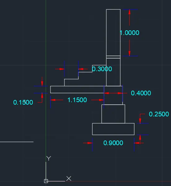
- AIM : DEAW THE CROSS SECTION OF A LOAD BEARING WALL OVER THE SPREAD FOOTING . USE THE AUTO CAD SOFTWARE TO DRAW THE C.S FOOTING :
- PROCEDURE :
- first the open the software
- give the command QNEW and press the ENTERE key
- click on imperical templete
- select ADVANCE SETUP
- unit : decimal , precision :0.00
- angle :decimal degree , precision :0.00
- angle measure : East
- angle direction : closkwise
- area : 20*20
- and finished , lets start
- give the ds command for some seeting
- snap spacing : x and y spacing =0.5
- grid spacing :x and y spacing =0.5
- press ok key
- give command REC for rectangle
- starting point is 1,1
- press DIMENSITION
- length :0.90
- width :0.25
- command REC
- starting point :1.2,1.25
- click on DIMENSITON
- length :0.50
- width :0.40
- give command REC
- starting point :1.25,1.65
- select DIMENSITION
- length :0.40
- width:0.40
- press ENTER key
- command :REC
- starting point :1.30,2.05
- click on DIMENSITION
- length :0.30
- width:0.60
- command :REC
- starting point :1.30,2.65
- select DIMENSITION option
- length :0.30
- width:0.05
- command :REC
- starting point :1.30,2.7
- select DIMENSITION option
- length:0.30
- width :1.0
- command :L for line
- starting point :1.25,2.05
- @0.15<270
- @1.15<180
- @0.15<90
- @1.15<0
- then closed
- command :L for line
- starting point : 0.40,2.05
- @0.15<90
- @0.30<0
- @0.15<90
- @0.30<0
- @0.15<90
- @0.30<0
- then closed
- RESULTS :
- cross section of load bearing wall over spread footing is given below :
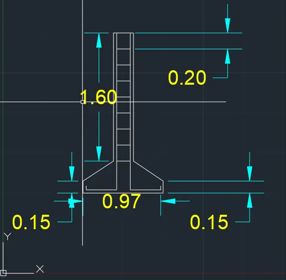
- AIM : TO DRAW THE CROSS SECTION OF ISOLATED FOOTING :
- PROCEDURE :
- give the command QNEW and press the ENTERE key
- click on imperical templete
- select ADVANCE SETUP
- unit : decimal , precision :0.00
- angle :decimal degree , precision :0.00
- angle measure : East
- angle direction : closkwise
- area : 20*20
- and finished , lets start
- give the ds command for some seeting
- snap spacing : x and y spacing =0.5
- grid spacing :x and y spacing =0.5
- press ok key
- command :L for line
- starting point :1,1
- @1<0
- @0.15<90
- press ENTER
- command : L for line
- starting point :1,1
- @0.15<90
- enter
- command: line
- starting point :1.04,1.04
- @0.38<0
- @1.96<90
- @0.17<0
- @1.96<270
- @0.38<0
- command : line
- starting point :1.04,1.04
- @0.05<90
- press : ENTER
- command : for line
- starting point :1.42,3.00
- @0.04<180
- @1.60<270
- then joint the cordinate (1.38,1.40) and (1,1.15) using line tool
- then , command :L
- starting point :1.59,3.00
- @0.04<0
- @1.60<270
- similarly above process join the coordinate
- then command :O for offset
- give
- offset distence 0.20
- press offset line and then select MULTIPLE option and give the offset
- press ENTER
- RESULTS :
- CEOSS SECTION OF A ISOLATED FOOTING GIVEN BELOW :
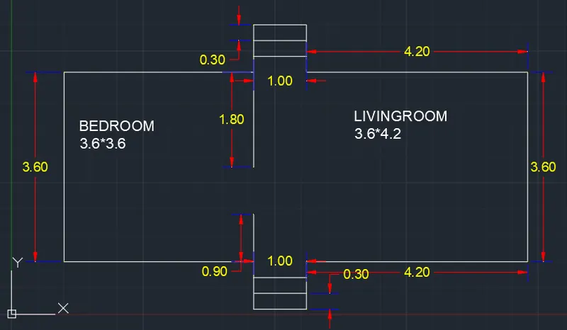
- AIM :DRAW A LINE DIAGRAM OF A TWO BEDROOM BUILDING :
- PROCEDURE :
- give the command QNEW and press the ENTERE key
- click on imperical templete
- select ADVANCE SETUP
- unit : decimal , precision :0.00
- angle :decimal degree , precision :0.00
- angle measure : East
- angle direction : closkwise
- area : 20*20
- and finished , lets start
- give the command QNEW and press the ENTERE key
- click on imperical templete
- select ADVANCE SETUP
- unit : decimal , precision :0.00
- angle :decimal degree , precision :0.00
- angle measure : East
- angle direction : closkwise
- area : 20*20
- and finished , lets start
- L for line
- starting point :1,1
- @3.60<0
- press :ENTER
- command :L
- starting point : 1,1
- @3.60<90
- @3.60<0
- @0.9<90
- @1<0
- @0.9<270
- @4.20<0
- @3.60<270
- @4.20<180
- @0.9<270
- @1<180
- @0.9<90
- closed
- command :L
- starting point : 4.60,1
- @0.9<90
- press :ENTER
- command :L
- starting point :4.60,4.60
- @1.80<270
- closed
- command :O for offset
- give the offset distence 0.30
- select offset line and option MULTIPLE
- give the officet and dimensition and finished it
- RESULTS :
- LINE DIAGRAM OF TWO BEDROOM IS GIVEN BELOW :
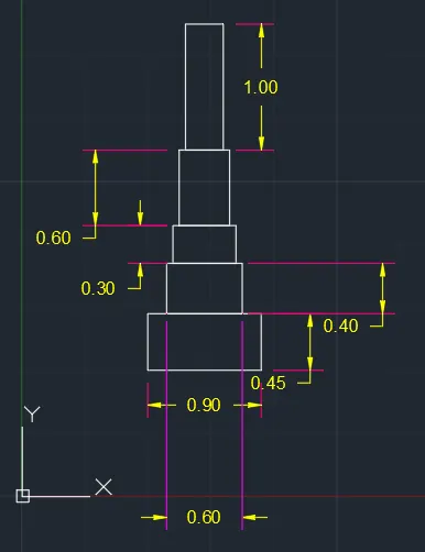
- DRAW THE CROSS SECTION OF A LOAD BEARING WALL WHICH SHOWS THE FOUNDATION DETAILS :
- PROCEDURE :
- give the command QNEW and press the ENTERE key
- click on imperical templete
- select ADVANCE SETUP
- unit : decimal , precision :0.00
- angle :decimal degree , precision :0.00
- angle measure : East
- angle direction : closkwise
- area : 20*20
- and finished , lets start
- give the command QNEW and press the ENTERE key
- click on imperical templete
- select ADVANCE SETUP
- unit : decimal , precision :0.00
- angle :decimal degree , precision :0.00
- angle measure : East
- angle direction : closkwise
- area : 20*20
- and finished , lets start
- command :REC for rectangle
- starting point :1,1
- press DIMENSITION
- length :0.90
- width :0.45
- press ENTER
- command :REC for rectangle
- starting point :1.15,1.45
- click on DIMENSITION
- length:0.60
- width :0.40
- press ENTER
- command :REC
- Starting point :1.20,1.85
- press DIMENSITION
- length:0.50
- width :0.30
- press ENTER
- Command :REC
- starting point :1.25,2.15
- click on DIMENSITION
- length :0.40
- width:0.60
- command :REC
- starting point :1.30,2.75
- click on DIMENSITION
- length :0.30
- width:1.00
- RESULTS :
- CROSS SECTION OF THE LOAD BEARING WALL SHOWING THE FOUNDATION DETAILS IS GIVEN BELOW :
 sn
sn
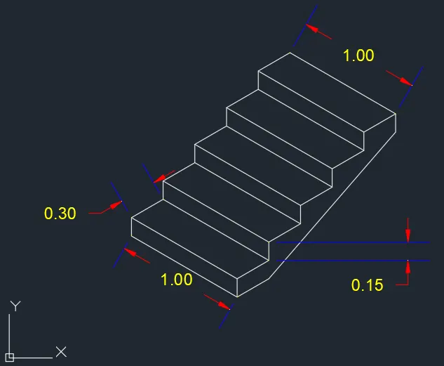
- AIM :DEAW THE ISOMATRIC VIEW OF A STEPS :
- PROCEDURE :
- Open the AUTOCAD SOFTWARE
- give the command QNEW
- press on imperical templets
- advance setup decimal
- angle : decimal degree precision :0.00
- and finished it
- give the command ds
- in drafting seating ,
- snap mode :off
- grid mode off
- isomatric snap: ON
- Ortho mode :ON
- Command :L for line
- starting point :1,1
- give the distence 1 and isoplane facing left
- then give the distance 0.15
- after that give the distance 0.30
- use isoplane fasing left ,right and top view
- this process is done till steps are formed
- RESULTS :
- ISOTROPIC VIEW OF A STEPS given below :
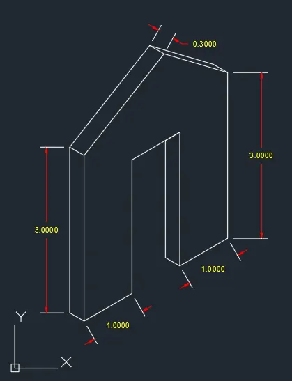
- AIM :DRAW THE ISOTROPHIC VIEW OF A GABLE WALL :
- PROCEDURE :
- Open the AUTOCAD SOFTWARE
- give the command QNEW
- press on imperical templets
- advance setup decimal
- angle : decimal degree precision :0.00
- and finished it
- give the command ds
- in drafting seating ,
- snap mode :off
- grid mode off
- isomatric snap: ON
- Ortho mode :ON
- give the line command
- select the starting point 1,1
- give the distence 3
- use isoplane top view
- give the distance 0.30 and draw
- then distance 1 and drow the door
- by giving peoper distance and use og isoplane top views, right views and left view complete the diagram
- RESULTS :
- ISOMATRIC VIEW OF GABLE WALL IS GIVEN BELOW