Simulink Stateflow Modeling of an Automatic Washing Machine and Gearbox
INTRODUCTION:
In today’s digital world, control logic/algorithm is perhaps one of the most important governing body of any automated system. Some of them rely on the user inputs while some others operate based on time delay settings. For example, the traffic signal lights that we encounter almost everyday depend on the time delay control logic. Irrespective of the traffic conditions, the traffic lights are programmed to function based on the time delays. There are several other applications where control logic is used for example, automatic gearbox, fully-automatic washing machine, dishwasher, electric cooker, etc.
AIM:
The aim of this project is to use the Simulink and Simscape blocks to model real world applications involving the state flow sequential logic. In the process, the different conditions in the state flow chart are studied.
OBJECTIVES:
The main objectives of this project include (i) to understand and implement the control logic of a fully-automatic washing machine using state flow with power and water supply as inputs (ii) to build a state flow model for an automatic transmission vehicle based on the speed input
SIMULINK MODEL DESCRIPTION AND GOVERNING EQUATIONS:
(i) Simulink Model and Control Logic for a fully automatic washing machine:
In a fully automatic washing machine, the only inputs are power supply, water inlet, clothes and detergent. The simulink model for a fully automatic washing machine is shown in Fig. 1a and 1b, for different input conditions. It should be noted here that only the output state of the recently completed process is shown in the screenshot of the simulink model in Fig. 1. Based on the time-delay input provided in the problem statement, a total run time of 400 seconds was chosen for the simulation. It is observed from Fig. 1a that only the power supply lamp indicator is green while the one for the water supply is red. This is because the water supply was set to “off” condition which results in stopping the machine operation and signaling the user to turn on the water supply. When the simulation is executed after turning on the water supply (shown in Fig. 1b), it is seen that all the processes get executed sequentially based on the time-delay input and once the cycle is completed, the user is notified via the process end lamp indicator.
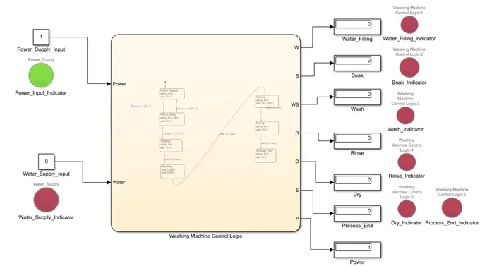
Figure 1a – Simulink model of a fully automatic washing machine with water supply off
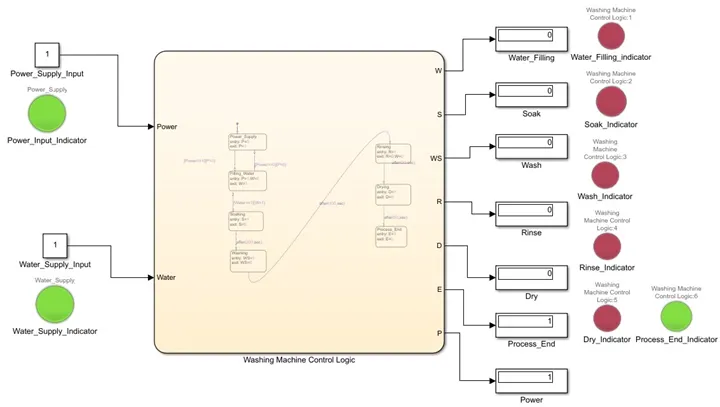
Figure 1b – Simulink model of a fully automatic washing machine with water supply on
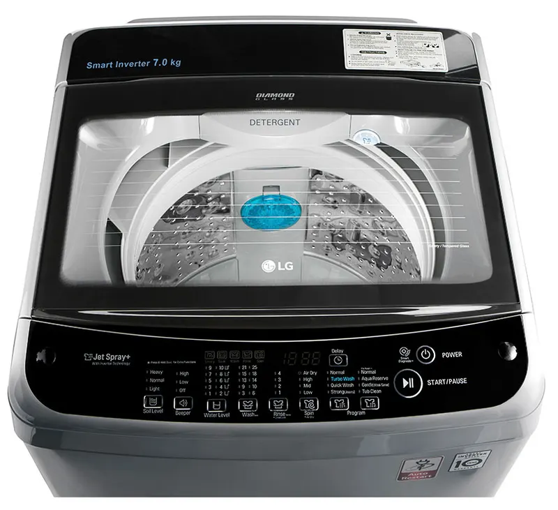
Figure 2 - LG fully-automatic washing machine [Ref: www.lg.com]
In Figure 2, an image of a LG brand fully-automatic washing machine is shown. Few things to note here are the various wash settings that is available to the user. Based on the master setting, the control logic triggers various washing cycles to best match the user inputs. Some of the washing cycles include, normal, heavy, wool, etc.
(ii) Stateflow chart for a fully automatic washing machine:
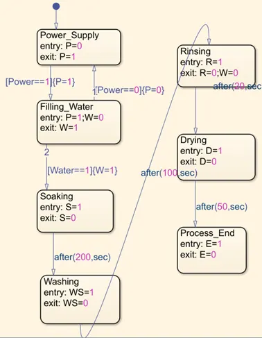
Figure 3 – Stateflow chart for a fully automatic washing machine
In the stateflow chart shown in Fig. 3, the various processes and the associated time-delays are outlined. As inferred from Fig. 3, power and water supply are the two inputs for the washing cycle to start. Once the inputs are detected, the soaking process starts and continues for 200 seconds. After this, the washing process takes over and continues for 100 seconds which is followed by rinsing the clothes for 20 seconds. Finally, the clothes are dried for 50 seconds before the process end indicator turn green signaling the end of the washing cycle to the user. Precisely, the cycle processes work based on the following governing equations:
Process1 + time-delay1 = Process2
Process2 + time-delay2 = Process3
………………..
ProcessN + time-delayN = ProcessN+1 ………………….. Eqn. [1]
In addition to the above outlined stateflow process, each process has an input and output. For example, as soon as the power and water supply are detected, the machine cycle starts. Several variables such as P, W, S, WS, R, D, E are specified to keep track of the active process. For example, when entering the soaking state, P=W=1; S=1 as the power and water supply are turned on and the soaking process is in progress (indicated using a lamp indicator). Once the soaking process is complete, ‘S’ will be set to 0 indicating to the user (via a lamp indicator) that the soaking process is complete.
(iii) Simulink Model and Control Logic for an automatic gearbox:
An automatic gearbox changes gears based on the speed of the automobile. A typical automatic gear-shift and the gear box system is shown in Figure 4. As noted from Fig. 4, the automatic gearbox has multiple clutch packs, brake band, oil pump (for lubrication), a torque converter and multiple bearings. It functions as an autonomous system once the drive train is engaged in the proper gear mode (i.e. drive, reverse, uphill , park, etc.). The simulink model for a fully automatic 6-speed gearbox is shown in Figure 5 for different input conditions. Instead of the driver shifting gears manually based on the speed of the automobile, an automatic gearbox uses a control logic to shift gears automatically by monitoring the speed of the automobile from the wheel rotation rpm. In this arrangement, the clutch assembly remains engaged with the drive-train at all times except when the gear shifting takes place.
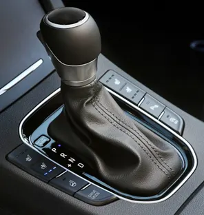
(a)
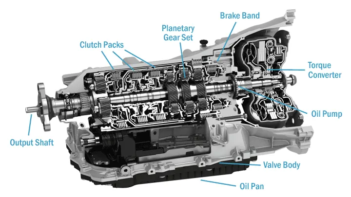
(b)
Figure 4 – (a) Automatic gear shift [Ref:www.gomechanic.in ] (b) Automatic gear box system [Ref: www.cartreatments.com]
In Fig. 5a, the input speed specified is 15 km per hour (i.e 15 kmph) which results in Gear-1. The active gear is indicated using a lamp indicator. In the real application, the display on the automobile dashboard indicates the gear number to the driver. When the speed is increased to 18 km per hour, the second gear is engaged (Fig. 5b). As the speed further increases to 30 km per hour, the third gear is engaged (Fig. 5c). Once the speed is increased to 50 kmph (Fig. 5d), the gear ratio (master gear to driven gear) has to be decreased to accommodate the higher speed thereby the system switches to Gear-4. The same process continues as the automobile speed is increased further (i.e. when the accelerator is pressed). When the speed increases beyond 80 kmph (Fig. 5f), the top gear (i.e. lowest gear ratio arrangement) is engaged for a smooth operation of the automobile. The threshold of operation for the various gears are given in Table-1.
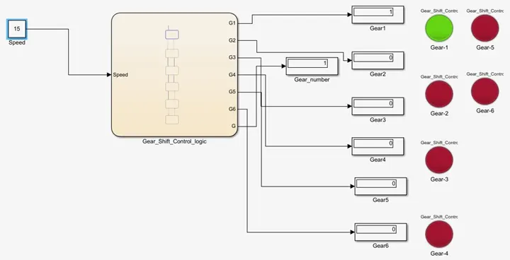
Figure 5a – Simulink model of an automatic gearbox with 15 km per hour speed input
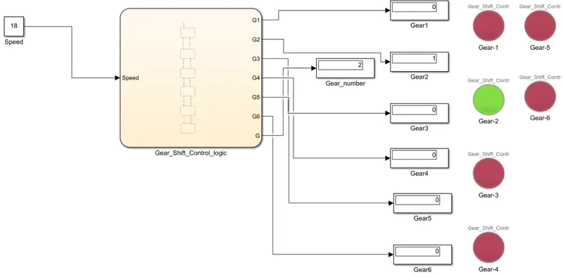
Figure 5b – Simulink model of an automatic gearbox with 18 km per hour speed input
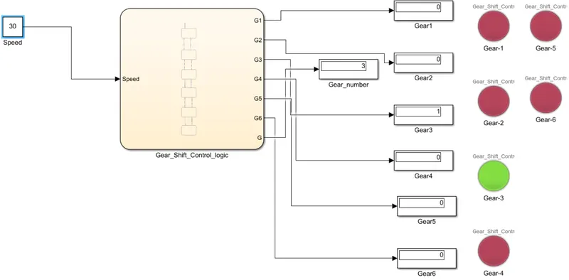
Figure 5c – Simulink model of an automatic gearbox with 30 km per hour speed input
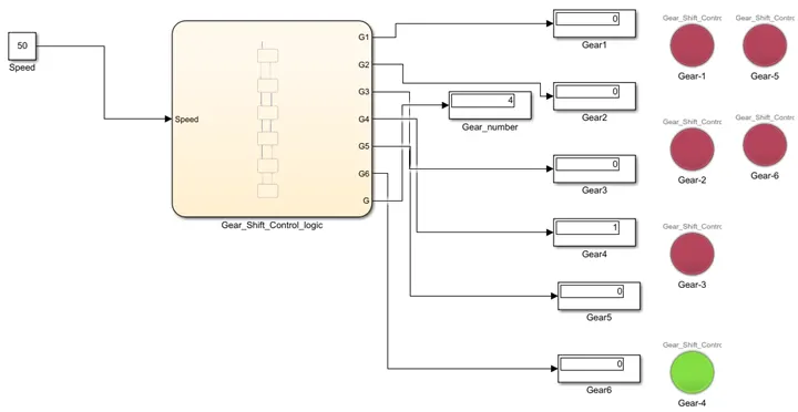
Figure 5d – Simulink model of an automatic gearbox with 50 km per hour speed input
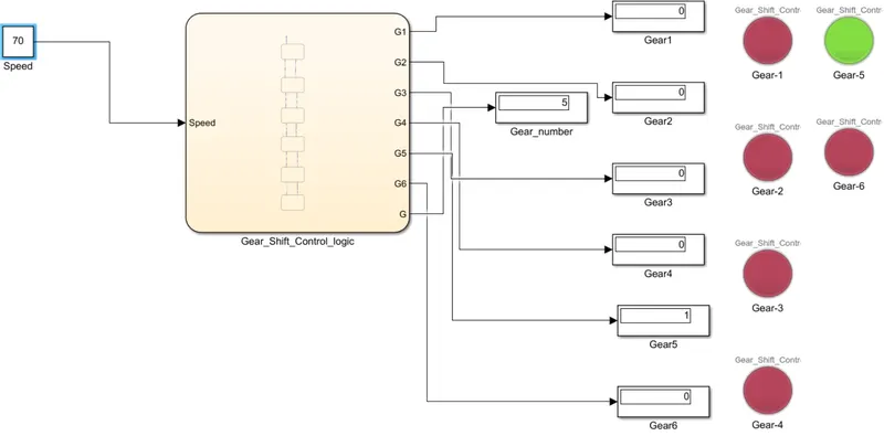
Figure 5e – Simulink model of an automatic gearbox with 70 km per hour speed input
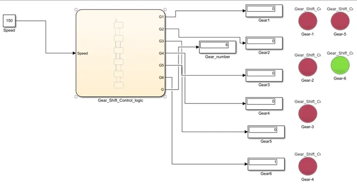
Figure 5f – Simulink model of an automatic gearbox with 150 km per hour speed input
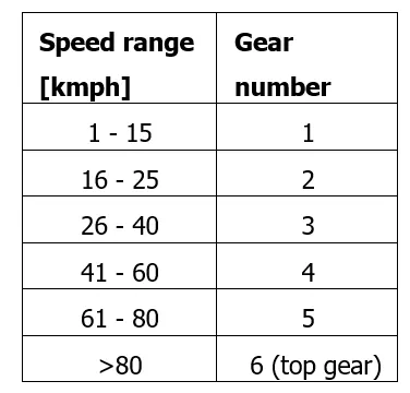
Table 1 – Threshold of speed for different gears
(iv) Stateflow chart for an automatic gearbox system:
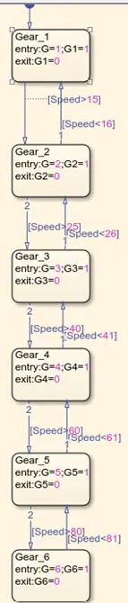
Figure 6 – Stateflow chart for a 6-speed automatic gearbox
In the gearbox stateflow chart shown in Fig. 6, the various processes and the associated time-delays are outlined. The stateflow starts with receiving the automobile speed as the only input from the “rpm” sensor mounted inside the wheel hub. Based on this input speed, the appropriate gear ratio (ratio of master gear to slave gear rpm) is selected by an algorithm. Once the gear ratio is set, the gear ratio which is suitable for that particular speed is selected (based on Table-1) and engaged by using the auto-clutch mechanism. As the speed changes with time, the gear changing algorithm dynamically alters the gear number to facilitate smooth operation of the vehicle gearbox and hence the ride quality. This type of operation is not standard in many cars as the equipment cost is quite high (compared to the manual transmission gearbox). On the other hand, these days, the fuel efficiency of automatic transmission cars are comparable to their manual gearbox counterparts.
Conclusions:
In this project, a thorough understanding of a fully automatic washing machine and automobile gearbox was developed using Simulink and Stateflow models. The stateflow models in Simulink were built after completely understanding the working algorithm of the automatic washing machine and gearbox. Multiple cases were chosen to check the working of the stateflow models to ensure that the result output is satisfactory. The time-delay for each cycle in the washing machine stateflow was specified based on the problem input. In the case of automatic gearbox, the input speed was used to ascertain the gear number. As a future work, it would be beneficial to incorporate realistic time-delays to the washing machine stateflow and realistic speed ranges for the various gear numbers in the automatic gearbox. Overall, this challenge paved way towards a fundamental understanding of the working algorithm of the most commonly used machines.
*****************************End of Report*******************************